Progress on OPTICAL FIBER AMPLIFIERS for 13 μm
6
Progress on OPTICAL FIBER for 1.3 µm BY MIKE BRIERLEY I n 1966, Kao and Hockham 1 and Werts 2 almost simul- taneously published papers that tied together semicon- ductor laser and glass fiber technologies, and proposed that the combination could be used to produce high bandwidth (information capacity) long distance com- munications links. This triggered the dream that one day optical communication links would span the world and would carry almost infinite amounts of information. Subsequent work over many years proved that there were limitations to the dream, principally in the signal loss in the fiber, the fibers tendency to temporally broaden pulses of light (dispersion), and the difficulty in produc- ing extremely short pulses. If the dream is to be realized, electronic repeaters and optical amplifiers are necessary, because today it is the loss of the fiber that is the principal limiting factor in the span of transmission systems. Twenty-five years later, many significant advances have been made, including the production of single mode fiber with loss close to its intrinsic minimum at 1.55 µm, the development of electronic repeater tech- nology, the realization of effective amplifiers, and the development of lasers that produce soliton pulses. The optical amplifier becomes the key component, making the regeneration of pulses by reshaping and retiming electronically unnecessary in many systems. Eco- nomically, this is useful because optical amplifiers are very much simpler and less expensive than electronic regenerative repeaters. Solitons—short intense light pulses in which the dispersion caused by the fiber is compensated by optical nonlinearities—further reduce the need for regenerative repeaters since dispersion can be removed from the equation. Indeed, a recent paper by Nakazawa et al., 3 reporting the equivalent of more than 70 simultaneous color TV channels trans- mitted over one million kilometers, demonstrates that the dream of the late 1960s is, in fact, achievable using 14 OPTICS & PHOTONICS NEWS/JANUARY 1992
Transcript of Progress on OPTICAL FIBER AMPLIFIERS for 13 μm
Progress on OPTICAL FIBER for 1.3 µm B Y M I K E B R I E R L E Y
I n 1966, Kao and H o c k h a m 1 and Wer ts 2 almost s imultaneously published papers that tied together semiconductor laser and glass fiber technologies, and proposed that the combination could be used to produce high bandwidth (information capacity) long distance communications links. This triggered the dream that one day optical communication l inks wou ld span the wor ld and would carry almost infinite amounts of information. Subsequent work over many years proved that there were limitations to the dream, principally in the signal loss in the fiber, the fibers tendency to temporally broaden pulses of light (dispersion), and the diff iculty in producing extremely short pulses. If the dream is to be realized, electronic repeaters and optical amplifiers are necessary, because today it is the loss of the fiber that is the principal l imiting factor in the span of transmission systems.
Twenty-five years later, many significant advances have been made, including the production of single
mode fiber wi th loss close to its intrinsic min imum at 1.55 µm, the development of electronic repeater technology, the realization of effective amplif iers, and the development of lasers that produce soliton pulses. The optical amplif ier becomes the key component, making the regeneration of pulses by reshaping and retiming electronically unnecessary in many systems. Economically, this is useful because optical amplifiers are very much simpler and less expensive than electronic regenerative repeaters. Solitons—short intense light pulses in which the dispersion caused by the fiber is compensated by optical nonlinearities—further reduce the need for regenerative repeaters since dispersion can be removed from the equation. Indeed, a recent paper by Nakazawa et al., 3 reporting the equivalent of more than 70 simultaneous color T V channels transmitted over one mi l l ion kilometers, demonstrates that the dream of the late 1960s is, in fact, achievable using
14 OPTICS & PHOTONICS NEWS/JANUARY 1992
AMPLIFIERS
solitons and amplifiers. The concept of an optical fiber amplif ier is actually older
than the concept of optical fiber communications; Koester and Snitzer 4 first demonstrated amplif ication in a fiber in 1964. However, it was Mears et al.5 in 1987 who demonstrated the erbium-doped silica fiber amplifier, now commonly referred to as the E D F A , as a practical amplif ier for telecommunications.This amplifier is produced by adding trivalent erbium ions to the core of fibers that are otherwise similar to standard telecommunications fiber. This has turned out to be an almost ideal device for increasing the span of point-to-point optical l inks, but has also opened the way for mult i -mi l l ion user broadband networks. 6 Interestingly, it is this E D F A technology that has enabled the development of semiconductor diode laser pumped soliton lasers, 7 which could turn Nakazawa's demonstration and current thinking on truly broadband local distribution networks into a practical reality.
A l l of the above depends on digital technology, but a further attribute of the E D F A is its ability to ampli fy analog signals, making it an extremely useful device in , for example, cable T V applications. In a sense, that is the good news, but as always there is a down-side. In this case, it is that 1.55 µm systems are stil l mostly in the laboratory. A l though they w i l l undoubtedly be the systems of the future, the vast majority of currently operational optical communications systems operate near to 1.3 µm wavelength; changing over to 1.55 µm technology could be very expensive. Consequently, a "1.3 µm E D F A " wou ld be a very useful device. In addit ion to al l the features listed above it wou ld offer the option of upgrading or extending existing systems at relatively low cost.
1.3 µM OPTICAL AMPLIFIERS
Unfortunately, nature has not been so k ind as to provide a direct equivalent to the E D F A wi th a 1.3 µm operating wavelength. Unt i l 1991, even a near approximation looked very elusive. However, both in advance of and in parallel w i th the
development of the E D F A , a number of options have been examined for amplifiers for 1.55 µm and 1.3 µm. Before looking at the most promising device, the praseodymium doped fluoride fiber amplifier—it w i l l be helpful to review the requirements of an ideal 1.3 µm amplif ier and "the competition."
Ideal specification: A n ideal optical ampli f ier for 1.3 µm w i l l be capable of h igh gain, greater than 30 dB (1000 times) between the incoming and outgoing fiber. It w i l l ampl i fy signals at least f rom 1.28-1.32 µm wavelength, and preferably shorter and longer, simultaneously and w i th the same gain at al l wavelengths. It w i l l operate bidirectionally w i th m in imum extra noise added to the signal. It w i l l not be sensitive to signal polarizat ion. It w i l l not have any interference between signals w i th in the gain-bandwidth (crosstalk), and w i l l operate on both analog and digital signals from kb i t / s to mul t i -G b i t / s . It should be very linear over a w ide range of input
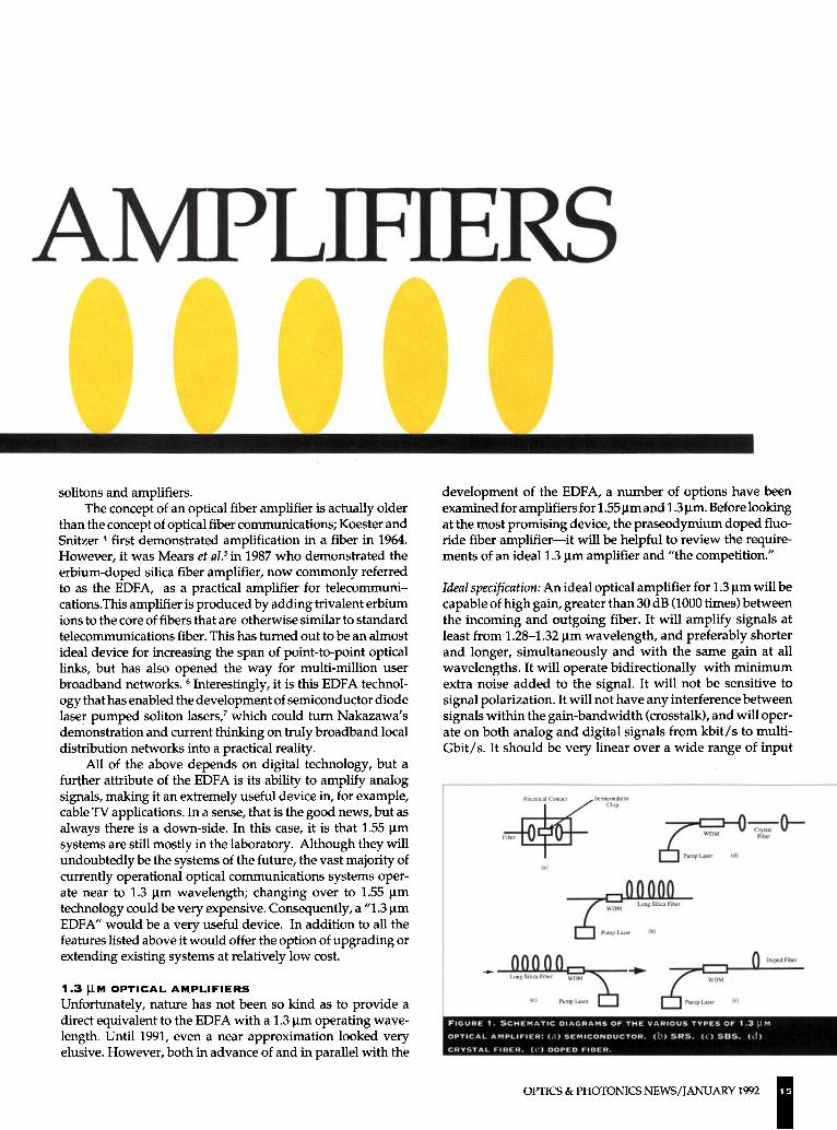
F I G U R E 1. S C H E M A T I C D I A G R A M S O F T H E V A R I O U S T Y P E S O F 1.3 µM
O P T I C A L A M P L I F I E R : (A) S E M I C O N D U C T O R . (b) SRS, (c) S B S , (d)
C R Y S T A L F IBER. (e) D O P E D F IBER.
OPTICS & PHOTONICS N E W S / J A N U A R Y 1992 15
levels and capable of h igh output power operation under saturated conditions. It should be reliable and self-contained, i.e., should not depend on physical ly large pump lasers, and should be power efficient. These are very diff icult specifications to meet, but the E D F A comes close in al l but wavelength—hence, the reason for researching a 1.3 µm alternative.
1.3 µm semiconductor laser amplifiers: A schematic of a semiconductor laser amplif ier appears in Figure 1 a. Unt i l very recently, this was the main contender for 1.3 µm amplifiers, though it had already given way to the E D F A for 1.55 µm communications. But this device falls short of the ideal specification in a number of key areas. First, it is highly nonlinear in operation, wh ich is desirable for such things as switching applications, but not for amplif ication. Second, the short carrier lifetime (1-
2 ns) leads to interference between adjacent channels. Thi rd, due to the shape of the waveguide structure, semiconductor laser amplifiers tend to be sensitive to incoming signal polarization. The gain spectrum is a superposition of the material gain spectrum and a residual Fabry-Perot response caused by reflections from the chip facets. This is much reduced by anti-reflection coating, but can still give significant variation from the required flat spectrum, particularly for signals closely spaced in wavelength. Coupl ing losses to fiber systems are high, around 6 dB, making the overall fiber to fiber gain requirement difficult to meet.
Recently, with the introduction of multi-quantum-wel l ( M Q W ) structures, i m provements to spectral bandwidth and p o l a r i z a t i o n sens i t i v i t y have been achieved, but crosstalk and bit-rate problems remain. Nevertheless, the semiconductor laser amplif ier is commercial ly available and fiber to fiber gains of 21 dB have been reported. 8 This device w i l l undoubtedly f ind application in areas where nonlinearity is advantageous, but is not now the favorite for communications amplification.
Nonlinear fiber amplifiers: Extremely h igh optical power densities can easily be achieved in single mode fibers wi th relatively modest actual powers; and that can lead to nonlinear effects in silica communications fibers. Stimulated Raman scattering (SRS) and stimulated Bri l louin scattering (SBS) both cause degradation to optical systems performance and, in fact, set a physical upper l imit to the power that can be employed. 9 However, both of these effects can be used to provide ampl i fication. (An excellent description of their operation is contained in Ref. 9.)
SBS amplifiers (Figure 1c) require only a few m W of pump power, at a wavelength equivalent to one Stokes shift shorter than the required amplif ier wavelength (approximately 0.062 nm at 1.3 µm) and can provide gains of up to 20 dB (100 times). Unfortunately, the spectral w id th
16 OPTICS & PHOTONICS NEWS/JANUARY 1992
over which gain can be obtained is significantly less than 1 nm, which immediately removes it f rom the list of ideal amplifiers. Ampli f icat ion occurs only in a direction counterpropagating to the pump, as indicated in the diagram (all the other ampl i fiers described in this article are bidrectional), wh ich again is a significant drawback.
SRS amplifiers (Figure lb ) again require a pump source one Stokes shift shorter wavelength than the required ampli f i cation (typically 80 n m at 1.3 µm), but w i th significantly greater power. They offer around 40 nm spectral bandwidth, but only at lower gain— around 10 dB for 200-300 m W of pump power in a specially designed fiber. In both SRS and SBS amplifiers, several kilometers of fiber are required to achieve realistic gains. There are certainly applications for such amplifiers, but again SRS and SBS amplifiers are far from ideal for telecommunications.
Rare-earth doped fiber amplifiers: The search for an ideal 1.3 µm amplifier leads us once again to rare earth doped fibers. A s described above, the E D F A offers a unique combination of features that makes it an almost ideal amplif ier for communications, so it wou ld seem that an equivalent rare-earth 1.3 µm transition should offer a similar combination. The rare-earths are the lanthanide series of elements, 58-71 in the periodic table. They have complete 4f shells, wh ich makes them relatively insensitive to their surroundings. In the triple ionized state, they can be excited optically to discrete energy states, described by energy level diagrams, examples of which appear in Figures 2 and 3. This process requires the absorption of photons of energy equivalent to the energy difference between the ions ground (lowest) energy state and the particular higher energy state (pump band). In a single crystal host material, each ion experiences identical fields, causing the absorption bands to be extremely narrow and hence requiring exact wavelengths for excitation. In amorphous hosts such as glasses, indiv idual ions experience slightly different fields causing the energy states and hence the absorption bands to be broader. This relaxes the specification on the exciting (pump) wavelength, and also offers the opportunity to excite directly into the band from which emission is desired.
Once in an excited state an ion may either absorb another photon, (either pump, signal, or emitted), if the photon energy matches the gap between the ion's present state and a higher state, and be excited to the higher energy level (excited state absorption or ESA) , or it w i l l lose energy. Energy is lost in one of three ways: by emission of a photon of energy equivalent to the difference between the excited state and a lower state (fluorescence), by emission of a photon stimulated by another photon, or by losing energy to the host material v ia phonons (non-radiative decay). It is the second of these processes that leads to amplification and lasing.
Whether the energy loss is radiative or non-radiative depends mainly on the phonon energy of the host, and this varies from host to host. For example, in a silica glass host, the min imum energy gap between energy states (levels) that w i l l al low fluorescence to dominate is 4600 cm- 1 , corresponding to 2.2 µm wavelength; in Z B L A N , it is 3100 cm - 1 , or 3.2 µm. The relevance of this brief explanation of processes w i l l become clear later.
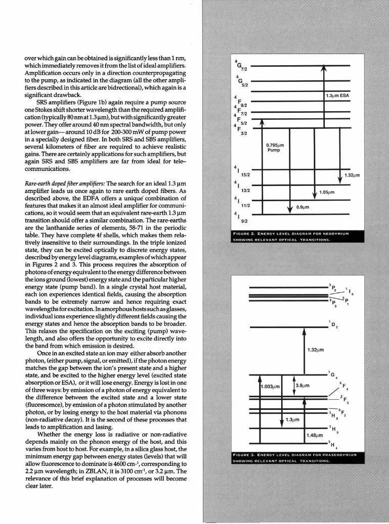
F I G U R E 2 . E N E R G Y L E V E L D I A G R A M F O R N E O D Y M I U M
S H O W I N G R E L E V A N T O P T I C A L T R A N S I T I O N S .
F I G U R E 3 . E N E R G Y L E V E L D I A G R A M F O R P R A S E O D Y M I U M
S H O W I N G R E L E V A N T O P T I C A L T R A N S I T I O N S .
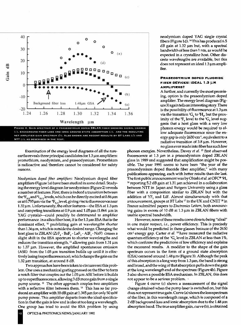
FIGURE 4. GAIN SPECTRUM OF A PRASEODYMIUM DOPED ZBLAN FIBER SHOWING SIGNAL CHANGE (C). BACKGROUND FIBER LOSS AND IONIC GROUND STATE ABSORPTION (A). AND THE RESULTING NET AMPLIFIER GAIN SPECTRUM (B), ALSO SHOWN ARE RECENT RESULTS BY BT LABS (D) AND NTT (E). AS DESCRIBED IN THE TEXT.
Examination of the energy level diagrams of al l the rare-earths reveals three principal candidates for 1.3 m amplifiers: promethium, neodymium, and praseodymium. Promethium is radioactive and therefore cannot be considered for safety reasons.
Neodymium doped fiber amplifiers: Neodymium doped fiber amplifiers (Figure 1 e) have been studied in some detail. Studying the energy level diagram for neodymium (Figure 2) reveals a number of features. First, there is indeed a transition between the 4 F 3 / 2 a n d 4 I 1 3 / 2 levels, which can be directly excited at 0.86 µm or at 0.795 µm via the 4 F 5 / 2 l e v e l , giving rise to fluorescence near 1.32 µm. Unfortunately, the other features—the E S A at 1.3 µm and competing transitions at 0.9 µm and 1.05 µm (1.064 µm in Y A G crystals)—could possibly be detrimental to amplifier performance. In a silica fiber host, it is the 1.3 µm E S A that is the dominant effect, 1 0 prohibit ing gain at wavelengths shorter than 1.36 µm, which is outside the desired range. Changing the host glass to Z B L A N (ZrF 4 - BaF 2 - LaF 3 - A1F 3 - NaF) causes a slight shift in the E S A spectrum to shorter wavelengths and reduces the transition strength, 1 1 a l lowing gain from 1.31 µm to 1.37 µm. However, the amplif ied spontaneous emission (ASE) from the 1.05 µm transition bui lds up unt i l it is effectively lasing (superfluorescence), wh ich clamps the gain on the 1.32 µm transition, at around 8 dB.
Two approaches have been taken to circumvent this problem. One uses a mechanical grating pressed on the fiber to form a notch filter that couples out the 1.05 µm A S E before it bui lds up to superfluorescence, al lowing 3 dB more gain from a single pump source. 1 2 The other approach couples two amplifiers wi th a reflective filter between t h e m . 1 3 This has so far produced an amplifier w i th 10 dB gain at 1.345 µm for only 50 m W pump power. This amplifier departs from the ideal specification in that the gain is low and is also at too long a wavelength. One group has tried to avoid the E S A problem by using
neodymium doped Y A G single crystal fibers (Figure 1d). 1 4This has produced 6.5 dB gain at 1.32 µm but, w i th a spectral bandwidth of less than 1 ran, as wou ld be expected in a crystalline host. Other discrete wavelengths are available, but this does not represent an ideal 1.3 µm ampl i fier.
PRASEODYMIUM DOPED FLUORIDE
FIBER DEVICES: IDEAL 1.3 µM
AMPLIFIERS?
A further, and currently the most promising, option is the praseodymium doped amplifier. The energy level diagram (Figure 3) again tells an interesting story. There is the possibil ity of fluorescence at 1.3 µm via the transition 1G4 to 3 H 5 , but the proximity of the 3 F 4 level to the 1G4 level suggests that a host glass wi th a very low phonon energy wou ld be required to a l low adequate fluorescence since the energy gap is only 2630 cm - 1 , equivalent to a radiative transition of 3.8 µm. However, no glass ever made into fiber has such low
phonon energies. Nevertheless, Davey et al.15 first observed fluorescence at 1.3 µm in a praseodymium doped Z B L A N glass in 1989 and suggested that amplif ication might be possible. The year 1991 seems to have been "the, year of the praseodymium doped fluoride fiber amplif ier," w i th many publications appearing, each w i th better results than the last. The first public announcement was by Ohish i et al. at OFC® '91, 1 6 reporting 5.2 dB gain at 1.31 µm achieved in a collaboration between N T T in Japan and Rutgers University using a glass fiber w i th a composit ion similar to Z B L A N but wi th the addit ion of Y F 3 and L iF . A lmost simultaneously w i th that announcement, groups at BT L a b s 1 7 in the U K and C N E T 1 8 in France submitted papers to Electronics Letters, both announcing gains in excess of 10 dB at 1.3 µm in Z B L A N fibers wi th usable spectral bandwidth.
However, none of these results come close to being " idea l " in one major respect, i.e., power efficiency. This is precisely what wou ld be. predicted in these glasses because of the 2630 cm - 1 energy gap. Carter et al.19 have measured the radiative quantum efficiency of the 1G4 level in Z B L A N at less than 1%, which confirms the predictions of low efficiency and explains the measured results. A modifier to the shape of the gain spectrum occurs in the form of a ground state absorption (GSA) centered around 1.48 µm (Figure 3). A l though the peak of this absorption is a long way from 1.3 µm, the band is strong and broad, and the w ing of that absorption pulls down the gain at the long wavelength end of the spectrum (Figure 4b). Figure 3 also shows a possible E S A mechanism. In Z B L A N , this does not appear to be a serious problem. -
Figure 4 curve (c) shows a measurement of the signal change obtained when the pump laser is switched on, but this does not represent true gain. Curve (a) shows the loss spectrum of the fiber, in this wavelength range, wh ich is composed of a 2 dB background loss and ionic absorption due to the 1.48 µm absorption band. The true amplifier gain, curve (b), is obtained
18 OPTICS & PHOTONICS N E W S / J A N U A R Y 1992
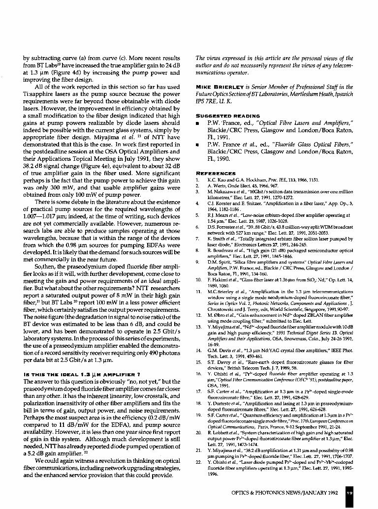
by subtracting curve (a) from curve (c). More recent results from BT Labs 2 0 have increased the true amplif ier gain to 24 dB at 1.3 µm (Figure 4d) by increasing the pump power and improving the fiber design.
A l l of the work reported in this section so far has used Ti:sapphire lasers as the pump source because the power requirements were far beyond those obtainable w i th diode lasers. However , the improvement in efficiency obtained by a small modif icat ion to the fiber design indicated that h igh gains at pump powers realizable by diode lasers should indeed be possible w i th the current glass systems, s imply by appropriate fiber design. Miya j ima et al. 2 1 of N T T have demonstrated that this is the case. In work first reported in the postdeadline session at the O S A Opt ical Ampl i f iers and their Appl icat ions Topical Meet ing in July 1991, they show 38.2 dB signal change (Figure 4e), equivalent to about 32 dB of true amplif ier gain in the fiber used. More significant perhaps is the fact that the pump power to achieve this gain was only 300 m W , and that usable ampli f ier gains were obtained from only 100 m W of pump power.
There is some debate in the literature about the existence of practical pump sources for the required wavelengths of 1.007—1.017 µm; indeed, at the time of wr i t ing, such devices are not yet commercially available. However, numerous research labs are able to produce samples operating at those wavelengths, because that is wi th in the range of the devices from which the 0.98 µm sources for pumping E D F A s were developed. It is l ikely that the demand for such sources w i l l be met commercially in the near future.
So,then, the praseodymium doped fluoride fiber ampl i fier looks as if it w i l l , wi th further development, come close to meeting the gain and power requirements of an ideal ampl i fier. But what about the other requirements? N T T researchers report a saturated output power of 8 m W in their h igh gain fiber, 2 1 but BT L a b s 2 0 report 100 m W in a less power efficient fiber, which certainly satisfies the output power requirements. The noise figure (the degradation in signal to noise ratio) of the BT device was estimated to be less than 6 dB, and could be lower, and has been demonstrated to operate in 2.5 G b i t / s laboratory systems. In the process of this series of experiments, the use of a praseodymium amplifier enabled the demonstration of a record sensitivity receiver requiring only 490 photons per data bit at 2.5 G b i t / s at 1.3 µm.
IS THIS T H E IDEAL 1.3 µM AMPLIFIER ?
The answer to this question is obviously "no, not yet," but the praseodymium doped fluoride fiber amplif ier comes far closer than any other. It has the inherent linearity, low crosstalk, and polarization insensitivity of other fiber amplifiers and fits the bi l l in terms of gain, output power, and noise requirements. Perhaps the most suspect area is in the efficiency (0.2 d B / m W compared to 11 d B / m W for the E D F A ) , and pump source availability. However, it is less than one year since first report of gain in this system. A l though much development is stil l needed, N T T has already reported diode pumped operation of a 5.2 dB gain ampl i f ier . 2 2
We could again witness a revolution in thinking on optical fiber communications, including network upgrading strategies, and the enhanced service provision that this could provide.
The views expressed in this article are the personal views of the author and do not necessarily represent the views of any telecommunications operator.
MIKE BRIERLEY IS Senior Member of Professional Staff in the Future Optics Section of BT Laboratories, Martlesham Heath, Ipswich IP5 7RE, U. K.
S U G G E S T E D READING
• P.W. France, ed., "Optical Fibre Lasers and Amplifiers," B l a c k i e / C R C Press, Glasgow and London/Boca Raton, F l . , 1991.
• P.W. France et al., ed., "Fluoride Glass Optical Fibers," B l a c k i e / C R C Press, Glasgow and London/Boca Raton, F l . , 1990.
R E F E R E N C E S
1. K.C. Kao and G.A. Hockham, Proc. IEE, 113, 1966, 1151. 2. A . Werts, Onde Elect. 45, 1966, 967. 3. M. Nakazawa et al., "10Gbit/s soliton data transmission over one million
kilometres," Elec. Lett. 27, 1991, 1270-1272. 4. C.J. Koester and E. Snitzer, "Amplification in a fiber laser," App. Op., 3,
1964, 1182-1186. 5. R.J. Mears et al., "Low-noise erbium-doped fiber amplifier operating at
1.54 µm," Elec. Lett. 23, 1987, 1026-1028. 6. D.S. Forrester et al., "39..81 Gbit/s, 43.8 million-way split W D M broadcast
network with 527 km range," Elec. Lett. 27, 1991, 2051-2053. 7. K. Smith et al., "Totally integrated erbium fiber soliton laser pumped by
laser diode," Electronics Letters 27, 1991, 244-245. 8. R. Boudreau et al., "High gain (21 dB) packaged semiconductor optical
amplifiers," Elec. Lett. 27, 1991, 1845-1846. 9. D.M. Spirit, "Silica fibre amplifiers and systems" Optical Fibre Lasers and
Amplifiers, P.W. France, ed., Blackie / CRC Press, Glasgow and London / Boca Raton, Fl., 1991, 134-160.
10. F. Hakimi et al., "Glass fiber laser at 1.36 µm from SiO 2: Nd," Op. Lett. 14, 1989, 1060.
11. M.C.Brierley et al., "Amplification in the 1.3 µm telecommunications window using a single mode neodymium-doped fluorozirconate fiber," Series in Optics Vol. 2, Photonic Networks, Components and Applications, J. Chrostowski and J. Terry, eds, World Scientific, Singapore, 1991,90-97.
12. M. 0bro et al., "Gain enhancement in N d 3 + doped Z B L A N fiber amplifier using mode coupling filter," submitted to Elec. Lett.
13. Y. Miyajima et al., "Nd 3 + -doped fluoride fiber amplifier module with 10 dB gain and high pump efficiency," 1991 Technical Digest Series 13, Optical Amplifiers and their Applications, OSA, Snowmass, Colo., July 24-26 1991, 16-19.
14. G.M. Davis et al., "1.3 µm Nd:YAG crystal fiber amplifiers," IEEE Phot. Tech. Lett. 3, 1991, 459-461.
15. S.T. Davey et al., "Rare-earth doped fluorozirconate glasses for fiber devices," British Telecom Tech. J. 7, 1989, 58.
16. Y. Ohishi et al., "Pr 3 +-doped fluoride fiber amplifier operating at 1.3 µm,"Optical Fiber Communication Conference (OFC® '91), postdeadline paper, OSA, 1991.
17. S.F. Carter et al., "Amplification at 1.3 µm in a Pr 3 +-doped single-mode fluorozirconate fibre," Elec. Lett. 27, 1991, 628-629.
18. Y. Durteste et al., "Amplification and lasing at 1.3 µm in praseodymium-doped fluorozirconate fibres," Elec. Lett. 27, 1991, 626-628.
19. S.F. Carter et al.,"Quantum efficiency and amplification at 1.3 µm in a Pr 3 +
doped fluorozirconate single mode fibre,"Proc. 17th European Conference on Optical Communications, Paris, France, 9-12 September 1991, 21-24.
20. R. Lobbett et al., "System characterization of high gain and high saturated output power Pr 3 +-doped fluorozirconate fiber amplifier at 1.3 µm," Elec. Lett. 27, 1991, 1473-1474.
21. Y. Miyajima et al., "38.2 dB amplification at 1.31 µm and possibility of 0.98 µm pumping in Pr 3 + -doped fluoride fiber," Elec. Lett. 27, 1991, 1706-1707.
22. Y. Ohishi et al., "Laser diode pumped Pr 3 +-doped and Pr 3 +-Yb 3 +-codoped fluoride fiber amplifiers operating at 1.3 µm," Elec. Lett. 27, 1991, 1995-1996.
OPTICS & P H O T O N I C S N E W S / J A N U A R Y 1992 1 9