Hollow Fiber Membrane Filter - Microsoft · Hollow Fiber Membrane Filter (PP) Warning 1. Carry out...
12
h t t p : / / w w w . p i s c o . c o . j p http://www.pisco.co.jp 182 ACTUATOR PLARAILCHAIN HARMO ROBOT PARTS In-line Filter Dry Unit Filter and Regulator Unit Small Type Dryer AIR PREPARATION Suitable for Semi-Conductor, Measuring Instrument, Printing and Medical Industries Hollow Fiber Membrane Filter ● Filtering Accuracy: 0.01μm, Correcting Efficiency: 99.99%, ● Small Body, Lightweight and Large Flow Rate ● Explosion-proof structure by a plastic body covering the filter case. ● Oil-Free, Stainless Steel and Cleanroom Package as standard specification. Cleanroom Package Non- Grease Copper alloy free
Transcript of Hollow Fiber Membrane Filter - Microsoft · Hollow Fiber Membrane Filter (PP) Warning 1. Carry out...

http://www.pisco.co.jphttp://www.pisco.co.jp
182
AC
TUA
TOR
PLARAILCHAINHARMO
ROBOT PARTSIn-line Filter
Dry U
nitFilter and Regulator Unit
Sm
all Type Dryer
AIRPREPARATION
Suitable for Semi-Conductor, Measuring Instrument, Printing and Medical IndustriesHollow Fiber Membrane Filter
●Filtering Accuracy: 0.01μm, Correcting Efficiency: 99.99%,
●Small Body, Lightweight and Large Flow Rate
●Explosion-proof structure by a plastic body covering the filter case.
●Oil-Free, Stainless Steel and Cleanroom Package as standard specification.
Cleanroom Package
Non-Grease
Copper alloy free
Hollow Fiber Membrane Filter
183
MPa0
0.5
1 Air preparation SeriesIn
-line
Filt
erD
ry U
nit
Filte
r and
Reg
ulato
r Unit
Sm
all T
ype
Dry
erSO
LEN
OID
VA
LVE
AIR
PREP
ALAT
ION
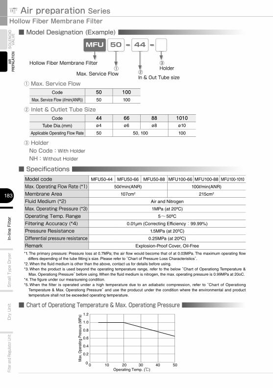
■ Model Designation (Example)
MFU 50 44
Hollow Fiber Membrane Filter①
Max. Service Flow ②In & Out Tube size
① Max. Service Flow
■ Specifi cationsModel code MFU50-44 MFU50-66 MFU50-88 MFU100-66 MFU100-88 MFU100-1010
Max. Operating Flow Rate (*1) 50l/min(ANR) 100l/min(ANR)
Membrane Area 107cm2 215cm2
Fluid Medium (*2) Air and Nitrogen
Max. Operating Pressure (*3) 1MPa (at 20ºC)
Operating Temp. Range 5~50ºC
Filtering Accuracy (*4) 0.01µm (Correcting Efficiency:99.99%)
Pressure Resistance 1.5MPa (at 20ºC)
Differential pressure resistance 0.25MPa (at 20ºC)
Remark Explosion-Proof Cover, Oil-Free
*1. The primary pressure: Pressure loss at 0.7MPa; the air flow would become that of at 0.03MPa. The maximum operating flow differs depending of the tube fitting’s size. Please refer to “Chart of Pressure Loss Characteristics”.
*2. When the fluid medium is other than the above, contact us for details before using.*3. When the product is used beyond the operating temperature range, refer to the below “Chart of Operationg Temperature &
Max. Operationg Pressure” before using. When the fluid medium is nitrogen, the max. operating pressure is 0.99MPa at 20oC.*4. The figure under our mearsureing condition.*5. When the filter is operated under a high temperature due to an adiabatic compression, refer to “Chart of Operationg
Temperature & Max. Operationg Pressure” and use the producut under the condition where the environmental and product temperature shall not be exceeded operating temperature.
③Holder
③ Holder No Code:With Holder NH:Without Holder
Code 50 100Max. Service Flow (l/min(ANR)) 50 100
② Inlet & Outlet Tube SizeCode 44 66 88 1010
Tube Dia.(mm) ø4 ø6 ø8 ø10
Applicable Operating Flow Rate 50 50, 100 100
■ Chart of Operationg Temperature & Max. Operationg Pressure
Max
. Ope
ratin
g Pr
essu
re (M
Pa)
Operating Temp. (℃)00
0.2
0.4
0.6
0.8
1.0
1.2
10 20 30 40 50
http://www.pisco.co.jphttp://www.pisco.co.jp
184
AC
TUA
TOR
PLARAILCHAINHARMO
ROBOT PARTSIn-line Filter
Dry U
nitFilter and Regulator Unit
Sm
all Type Dryer
AIRPREPARATION
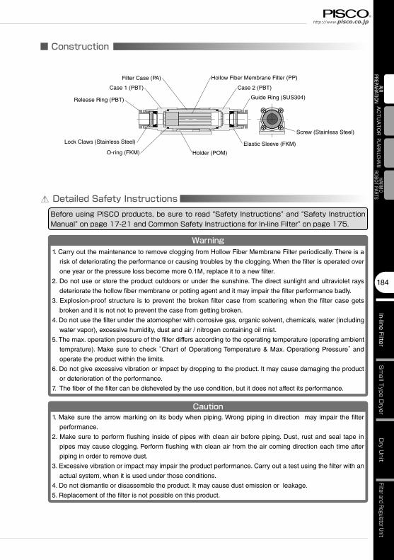
■ Construction
Guide Ring (SUS304)
Elastic Sleeve (FKM)
Holder (POM)
Release Ring (PBT)
Lock Claws (Stainless Steel)
Case 1 (PBT)
Detailed Safety InstructionsBefore using PISCO products, be sure to read “Safety Instructions” and “Safety Instruction Manual” on page 17-21 and Common Safety Instructions for In-line Filter” on page 175.
Screw (Stainless Steel)
O-ring (FKM)
Hollow Fiber Membrane Filter (PP)
Warning1. Carry out the maintenance to remove clogging from Hollow Fiber Membrane Filter periodically. There is a
risk of deteriorating the performance or causing troubles by the clogging. When the filter is operated over
one year or the pressure loss become more 0.1M, replace it to a new filter.
2. Do not use or store the product outdoors or under the sunshine. The direct sunlight and ultraviolet rays
deteriorate the hollow fiber membrane or potting agent and it may impair the filter performance badly.
3. Explosion-proof structure is to prevent the broken filter case from scattering when the filter case gets
broken and it is not not to prevent the case from getting broken.
4. Do not use the filter under the atomospher with corrosive gas, organic solvent, chemicals, water (including
water vapor), excessive humidity, dust and air / nitrogen containing oil mist.
5. The max. operation pressure of the filter differs according to the operating temperature (operating ambient
temprature). Make sure to check “Chart of Operationg Temperature & Max. Operationg Pressure” and
operate the product within the limits.
6. Do not give excessive vibration or impact by dropping to the product. It may cause damaging the product
or deterioration of the performance.
7. The fiber of the filter can be disheveled by the use condition, but it does not affect its performance.
Caution1. Make sure the arrow marking on its body when piping. Wrong piping in direction may impair the filter
performance.
2. Make sure to perform flushing inside of pipes with clean air before piping. Dust, rust and seal tape in
pipes may cause clogging. Perform flushing with clean air from the air coming direction each time after
piping in order to remove dust.
3. Excessive vibration or impact may impair the product performance. Carry out a test using the filter with an
actual system, when it is used under those conditions.
4. Do not dismantle or disassemble the product. It may cause dust emission or leakage.
5. Replacement of the filter is not possible on this product.
Filter Case (PA)
Case 2 (PBT)
Hollow Fiber Membrane Filter
185
MPa0
0.5
1 Air preparation SeriesIn
-line
Filt
erD
ry U
nit
Filte
r and
Reg
ulato
r Unit
Sm
all T
ype
Dry
erSO
LEN
OID
VA
LVE
AIR
PREP
ALAT
ION
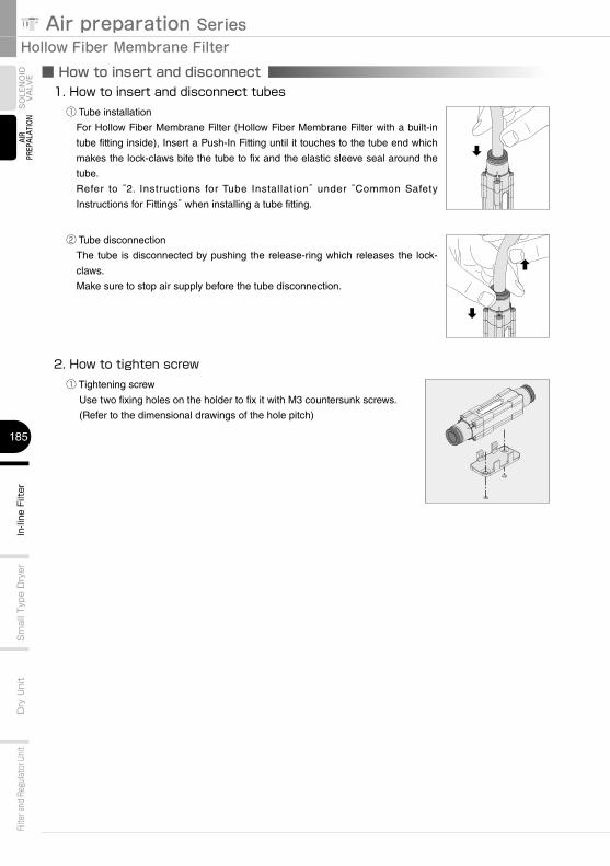
■ How to insert and disconnect1. How to insert and disconnect tubes① Tube installation
For Hollow Fiber Membrane Filter (Hollow Fiber Membrane Filter with a built-in
tube fitting inside), Insert a Push-In Fitting until it touches to the tube end which
makes the lock-claws bite the tube to fix and the elastic sleeve seal around the
tube.
Refer to “2. Instructions for Tube Installation” under “Common Safety
Instructions for Fittings” when installing a tube fitting.
② Tube disconnection
The tube is disconnected by pushing the release-ring which releases the lock-
claws.
Make sure to stop air supply before the tube disconnection.
2. How to tighten screw① Tightening screw
Use two fixing holes on the holder to fix it with M3 countersunk screws.
(Refer to the dimensional drawings of the hole pitch)
http://www.pisco.co.jphttp://www.pisco.co.jp
186
AC
TUA
TOR
PLARAILCHAINHARMO
ROBOT PARTSIn-line Filter
Dry U
nitFilter and Regulator Unit
Sm
all Type Dryer
AIRPREPARATION
CAD data is available at PISCO website.CAD3D CAD data is available at PISCO website.CAD3D
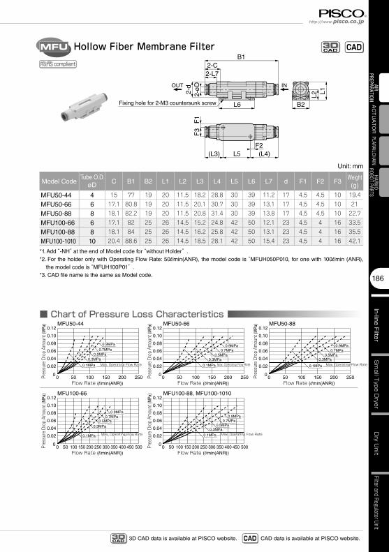
■ Chart of Pressure Loss Characteristics
Unit: mm
Model CodeTube O.D.
øD C B1 B2 L1 L2 L3 L4 L5 L6 L7 d F1 F2 F3Weight(g)
MFU50-44 4 15 77 19 20 11.5 18.2 28.8 30 39 11.2 17 4.5 4.5 10 19.4
MFU50-66 6 17.1 80.8 19 20 11.5 20.1 30.7 30 39 13.1 17 4.5 4.5 10 21
MFU50-88 8 18.1 82.2 19 20 11.5 20.8 31.4 30 39 13.8 17 4.5 4.5 10 22.7
MFU100-66 6 17.1 82 25 26 14.5 15.2 24.8 42 50 12.1 23 4.5 4 16 33.5
MFU100-88 8 18.1 84 25 26 14.5 16.2 25.8 42 50 13.1 23 4.5 4 16 35.5
MFU100-1010 10 20.4 88.6 25 26 14.5 18.5 28.1 42 50 15.4 23 4.5 4 16 42.1
*1. Add “-NH” at the end of Model code for “without Holder” .*2. For the holder only with Operating Flow Rate: 50l/min(ANR), the model code is “MFUH050P010, for one with 100l/min (ANR),
the model code is “MFUH100P01” .*3. CAD fi le name is the same as Model code.
Hollow Fiber Membrane FilterMFU
compliant
L6
L5(L3) (L4)F2
2-L72-C
OUT
B1
B2
2-ø
D2-
dF
3F
1
L2 L1
Fixing hole for 2-M3 countersunk screw
IN
CADCAD3D
MFU50-44 MFU50-66 MFU50-88
00
100 15050 200 250 300 350 400 450 500
MFU100-66
Pres
sure
Dro
p Am
ount
(MPa
)
Flow Rate (l/min(ANR))
MFU100-88, MFU100-1010
Pres
sure
Dro
p Am
ount
(MPa
)
Flow Rate (l/min(ANR))
Pres
sure
Dro
p Am
ount
(MPa
)
Flow Rate (l/min(ANR))
Pres
sure
Dro
p Am
ount
(MPa
)
Flow Rate (l/min(ANR))0
0
0.02
0.04
0.06
0.08
0.10
0.12
0.02
0.04
0.06
0.08
0.10
0.12
00
100 15050 200 250 300 350 400 450 500
0.02
0.04
0.06
0.08
0.10
0.12
50 100 150 200 250 00
0.02
0.04
0.06
0.08
0.10
0.12
50 100 150 200 250 00
0.02
0.04
0.06
0.08
0.10
0.12
50 100 150 200 250Pres
sure
Dro
p Am
ount
(MPa
)
Flow Rate (l/min(ANR))
Max. Operating Flow RateMax. Operating Flow Rate
Max. Operating Flow RateMax. Operating Flow Rate Max. Operating Flow RateMax. Operating Flow Rate
Max. Operating Flow RateMax. Operating Flow Rate Max. Operating Flow RateMax. Operating Flow Rate
0.1MPa
0.3MPa0.5MPa
0.7MPa0.9MPa
0.1MPa
0.3MPa0.5MPa
0.7MPa0.9MPa
0.1MPa
0.3MPa0.5MPa
0.7MPa
0.9MPa
0.1MPa
0.3MPa0.5MPa
0.7MPa0.9MPa
0.1MPa
0.3MPa0.5MPa
0.7MPa0.9MPa

Hollow Fiber Membrane Filter
187
MPa0
0.5
1 Air preparation SeriesIn
-line
Filt
erD
ry U
nit
Filte
r and
Reg
ulato
r Unit
Sm
all T
ype
Dry
erSO
LEN
OID
VA
LVE
AIR
PREP
ALAT
ION
17
Safety Instructions
SAFETY Instructions
Warning
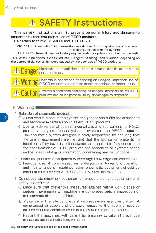
This safety instructions aim to prevent personal injury and damage to properties by requiring proper use of PISCO products. Be certain to follow ISO 4414 and JIS B 8370
ISO 4414:Pneumatic fluid power…Recomendations for the application of equipment to transmission and control systems.
JIS B 8370:General rules and safety requirements for systems and their components.This safety instructions is classified into “Danger”, “Warning” and “Caution” depending on the degree of danger or damages caused by improper use of PISCO products.
1. Selection of pneumatic products① A user who is a pneumatic system designer or has sufficient experience
and technical expertise should select PISCO products.② Due to wide variety of operating conditions and applications for PISCO
products, carry out the analysis and evaluation on PISCO products. The pneumatic system designer is solely responsible for assuring that the user's requirements are met and that the application presents no health or safety hazards. All designers are required to fully understand the specifications of PISCO products and constitute all systems based on the latest catalog or information, considering any malfunctions.
2. Handle the pneumatic equipment with enough knowledge and experience① Improper use of compressed air is dangerous. Assembly, operation
and maintenance of machines using pneumatic equipment should be conducted by a person with enough knowledge and experience.
3. Do not operate machine / equipment or remove pneumatic equipment until safety is confirmed.① Make sure that preventive measures against falling work-pieces or
sudden movements of machine are completed before inspection or maintenance of these machine.
② Make sure the above preventive measures are completed. A compressed air supply and the power supply to the machine must be off, and also the compressed air in the systems must be exhausted.
③ Restart the machines with care after ensuring to take all preventive measures against sudden movements.
Danger Hazardous conditions. It can cause death or serious personal injury.
Warning Hazardous conditions depending on usages. Improper use of PISCO products can cause death or serious personal injury.
Caution Hazardous conditions depending on usages. Improper use of PISCO products can cause personal injury or damages to properties.
※ . This safety instructions are subject to change without notice.

http://www.pisco.co.jphttp://www.pisco.co.jp
18
Disclaimer1. PISCO does not take any responsibility for any incidental or indirect
loss, such as production line stop, interruption of business, loss of benefits, personal injury, etc., caused by any failure on use or application of PISCO products.
2. PISCO does not take any responsibility for any loss caused by natural disasters, fires not related to PISCO products, acts by third parties, and intentional or accidental damages of PISCO products due to incorrect usage.
3. PISCO does not take any responsibility for any loss caused by improper usage of PISCO products such as exceeding the specification limit or not following the usage the published instructions and catalog allow.
4. PISCO does not take any responsibility for any loss caused by remodeling of PISCO products, or by combinational use with non-PISCO products and other software systems.
5. The damages caused by the defect of Pisco products shall be covered but limited to the full amount of the PISCO products paid by the customer.

19
Safety Instructions
SAFETY INSTRUCTION MANUAL
Danger1. Do not use PISCO products for the following applications.
① Equipment used for maintaining / handling human life and body.② Equipment used for moving / transporting human.③ Equipment specifically used for safety purposes.
Warning1. Do not use PISCO products under the following conditions.
① Beyond the specifications or conditions stated in the catalog, or the instructions.② Under the direct sunlight or outdoors.③ Excessive vibrations and impacts.④ Exposure / adhere to corrosive gas, inflammable gas, chemicals, seawater, water and vapor. *
* Some products can be used under the condition above(④), refer to the details of specification and condition of each product.
2. Do not disassemble or modify PISCO products, which affect the performance, function, and basic structure of the product.
3. Turn off the power supply, stop the air supply to PISCO products, and make sure there is no residual air pressure in the pipes before maintenance and inspection.
4. Do not touch the release-ring of push-in fitting when there is a working pressure. The lock may be released by the physical contact, and tube may fly out or slip out.
5. Frequent switchover of compressed air may generate heat, and there is a risk of causing burn injury.
6. Avoid any load on PISCO products, such as a tensile strength, twisting and bending. Otherwise, there is a risk of causing damage to the products.
7. As for applications where threads or tubes swing / rotate, use Rotary Joints, High Rotary Joints or Multi-Circuit Rotary Block only. The other PISCO products can be damaged in these applications.
8. Use only Die Temperature Control Fitting Series, Tube Fitting Stainless SUS316 Series, Tube Fitting Stainless SUS316 Compression Fitting Series or Tube Fitting Brass Series under the condition of over 60℃ (140°F) water or thermal oil. Other PISCO products can be damaged by heat and hydrolysis under the condition above.
9. As for the condition required to dissipate static electricity or provide an antistatic performance, use EG series fitting and antistatic products only, and do not use other PISCO products. There is a risk that static electricity can cause system defects or failures.
10. Use only Fittings with a characteristic of spatter-proof such as Anti-spatter or Brass series in a place where flame and weld spatter is produced. There is a risk of causing fire by sparks.
11. Turn off the power supply to PISCO products, and make sure there is no residual air pressure in the pipes and equipment before maintenance. Follow the instructions below in order to ensure safety.① Make sure the safety of all systems related to PISCO products before maintenance.② Restart of operation after maintenance shall be proceeded with care after
ensuring safety of the system by preventive measures against unexpected movements of machines and devices where pneumatic equipment is used.
③ Keep enough space for maintenance when designing a circuit.12. Take safety measures such as providing a protection cover if there is a
risk of causing damages or fires on machine / facilities by a fluid leakage.
PISCO products are designed and manufactured for use in general industrial machines. Be sure to read and follow the instructions below.

http://www.pisco.co.jphttp://www.pisco.co.jp
20
Caution1. Remove dusts or drain before piping. They may get into the peripheral
machine / facilities and cause malfunction.2. When inserting an ultra-soft tube into push-in fitting, make sure to place
an Insert Ring into the tube edge. There is a risk of causing the escape of tube and a fluid leakage without using an Insert Ring.
3. The product incorporating NBR as seal rubber material has a risk of malfunction caused by ozone crack. Ozone exists in high concentrations in static elimination air, clean-room, and near the high-voltage motors, etc. As a countermeasure, material change from NBR to HNBR or FKM is necessary. Consult with PISCO for more information.
4. Special option “Oil-free” products may cause a very small amount of a fluid leakage. When a fluid medium is liquid or the products are required to be used in harsh environments, contact us for further information.
5. In case of using non-PISCO brand tubes, make sure the tolerance of the outer tube diameter is within the limits of Table 1.
●Table 1. Tube O.D. Tolerancemm size Nylon tube Polyurethane tube inch size Nylon tube Polyurethane tubeø1.8mm ─ ±0.05mm ø1/8 ±0.1mm ±0.15mmø3mm ─ ±0.15mm ø5/32 ±0.1mm ±0.15mmø4mm ±0.1mm ±0.15mm ø3/16 ±0.1mm ±0.15mmø6mm ±0.1mm ±0.15mm ø1/4 ±0.1mm ±0.15mmø8mm ±0.1mm ±0.15mm ø5/16 ±0.1mm ±0.15mmø10mm ±0.1mm ±0.15mm ø3/8 ±0.1mm ±0.15mmø12mm ±0.1mm ±0.15mm ø1/2 ±0.1mm ±0.15mmø16mm ±0.1mm ±0.15mm ø5/8 ±0.1mm ±0.15mm
6. Instructions for Tube Insertion① Make sure that the cut end surface of the tube is at right angle without
a scratch on the surface and deformations.② When inserting a tube, the tube needs to be inserted fully into the push-
in fitting until the tubing edge touches the tube end of the fitting as shown in the figure below. Otherwise, there is a risk of leakage.
Tube end
Sealing
Tube is not fully inserted up to tube end.
③ After inserting the tube, make sure it is inserted properly and not to be disconnected by pulling it moderately.
※. When inserting tubes, Lock-claws may be hardly visible in the hole, observed from the front face of the release-ring. But it does not mean the tube will surely escape. Major causes of the tube escape are the followings; ①Shear drop of the lock-claws edge②The problem of tube diameter (usually small)Therefore, follow the above instructions from ① to ③, even lock-claws is hardly visible.
21
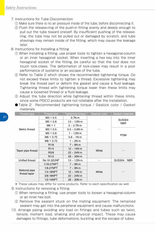
7. Instructions for Tube Disconnection① Make sure there is no air pressure inside of the tube, before disconnecting it.② Push the release-ring of the push-in fitting evenly and deeply enough to
pull out the tube toward oneself. By insufficient pushing of the release-ring, the tube may not be pulled out or damaged by scratch, and tube shavings may remain inside of the fitting, which may cause the leakage later.
8. Instructions for Installing a fitting① When installing a fitting, use proper tools to tighten a hexagonal-column
or an inner hexagonal socket. When inserting a hex key into the inner hexagonal socket of the fitting, be careful so that the tool does not touch lock-claws. The deformation of lock-claws may result in a poor performance of systems or an escape of the tube.
② Refer to Table 2 which shows the recommended tightening torque. Do not exceed these limits to tighten a thread. Excessive tightening may break the thread part or deform the gasket and cause a fluid leakage. Tightening thread with tightening torque lower than these limits may cause a loosened thread or a fluid leakage.
③ Adjust the tube direction while tightening thread within these limits, since some PISCO products are not rotatable after the installation.
●Table 2: Recommended tightening torque / Sealock color / Gasket materialsThread type Thread size Tightening torque Sealock color Gasket materials
Metric thread
M3×0.5 0.7N·m
─
SUS304NBR
M5×0.8 1.0 ~ 1.5N·mM6×1 2 ~ 2.7N·m
M3×0.5 0.5 ~ 0.6N·m
POMM5×0.8 1 ~ 1.5N·mM6×0.75 0.8 ~ 1N·mM8×0.75 1 ~ 2N·m
Taper pipe thread
R1/8 7 ~ 9N·m
White ─R1/4 12 ~ 14N·mR3/8 22 ~ 24N·mR1/2 28 ~ 30N·m
Unified thread No.10-32UNF 1.0 ~ 1.5N·m ─ SUS304、NBR
National pipe thread taper
1/16-27NPT 7 ~ 9N·m
White ─1/8-27NPT 7 ~ 9N·m1/4-18NPT 12 ~ 14N·m3/8-18NPT 22 ~ 24N·m1/2-14NPT 28 ~ 30N·m
※ These values may differ for some products. Refer to each specification as well.9. Instructions for removing a fitting
① When removing a fitting, use proper tools to loosen a hexagonal-column or an inner hex bolt.
② Remove the sealant stuck on the mating equipment. The remained sealant may get into the peripheral equipment and cause malfunctions.
10. Arrange piping avoiding any load on fittings and tubes such as twist, tensile, moment load, shaking and physical impact. These may cause damages to fittings, tube deformations, bursting and the escape of tubes.
Safety Instructions

MPa0
0.5
1 Air preparation Series
175
AIR
PREP
ALAT
ION
SOLE
NO
ID
VALV
E
Warning
Before selecting or using PISCO products, read the following instructions. Read the detailed instructions for individual series.
1. Each device has its control direction. Check it in this caltalog and the mark indicated on the product before using. Wrong control direction may cause injuries on the operator or damage to the equipment.
2. Avoid any load such as a tensile strength, twisting, bending, falling and an excessive force on products. Otherwise, there is a risk of damaging to products.
3. Implement periodic maintenances for the filter element. There is a risk of impairing the performance or causing troubles by the clogging. Thoroughly read and understand the instructions of replacing elements or removing dust in this catalog. Make sure to release the residual pressure completely in the system before the maintenance.
Caution1. Refer to “Common Safety Instructions for Fittings” for handling of fittings.
2. Make sure the direction of “IN” and “OUT” in this manual or the indication on products when piping. Wrong direction of installation may impair the filtering function.
3. Make sure to place the filter case properly and that there is no leakage after removing dust or replacing elements.
Common Safety Instructions for In-line Filter