Pixhawk and other electronics - Purdue University
21
Pixhawk and other electronics A primer Phil Baldwin 11/8/19
Transcript of Pixhawk and other electronics - Purdue University

Pixhawk and other electronicsA primer
Phil Baldwin11/8/19

Electrical Units• Voltage
• Volts (V)• “Flow” potential• The only supplied value by a battery
• Resistance• Ohms (Ω)• Characteristic of a circuit
• Current• Amps (A)• Resultant of potential and resistance
• Power• Watts (W)• 1 J/s
2
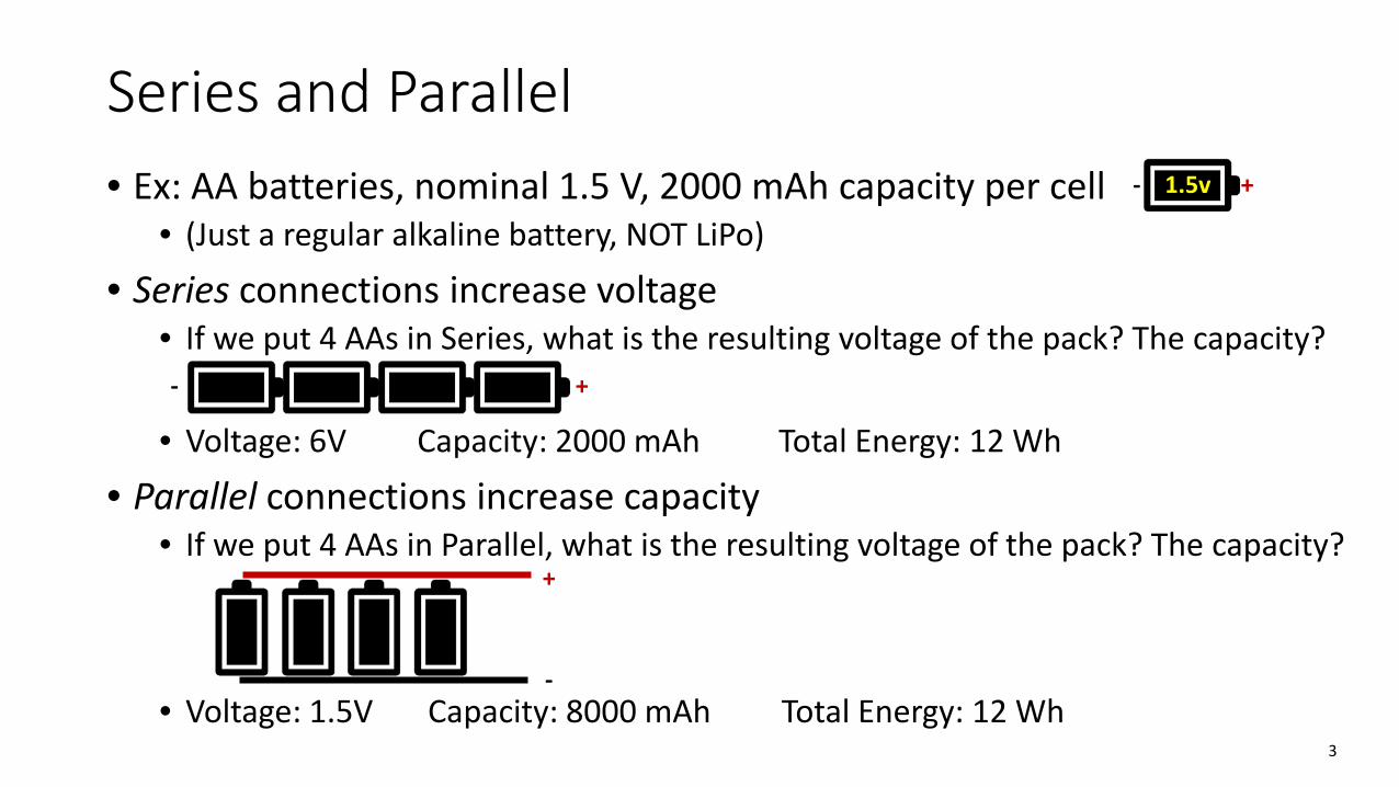
Series and Parallel• Ex: AA batteries, nominal 1.5 V, 2000 mAh capacity per cell
• (Just a regular alkaline battery, NOT LiPo)
• Series connections increase voltage• If we put 4 AAs in Series, what is the resulting voltage of the pack? The capacity?
• Voltage: 6V Capacity: 2000 mAh Total Energy: 12 Wh
• Parallel connections increase capacity• If we put 4 AAs in Parallel, what is the resulting voltage of the pack? The capacity?
• Voltage: 1.5V Capacity: 8000 mAh Total Energy: 12 Wh3
- 1.5v +
- +
+
-

LiPo Batteries
• Provides an electrical potential → Voltage• Is constructed of cells of a given capacity (mAh)
• Capacity is current * time, hence Amps (or milliamps), over an hour• Describing a battery by saying “it has 7000 milliamps” is nonsensical, though
we can probably guess what you mean
• Does not “provide” a set amperage• Ex: a 20C 4000 mAh LiPo can pump out 80A without damaging the battery,
but it will NOT pump out 80A all the time
• Most LiPos are sold as a nS1P arrangement, where n is the number of cells in series, and there is just that one set of serial cells (i.e. no parallel arrangement)
4
LiPos – Parallel and Series• Generally buy a battery with the series arrangement already done
• Example: You design your propulsion system to use a 4S battery. It is much easier (and probably cheaper) to buy a 4S battery than two 2S batteries and put them in series
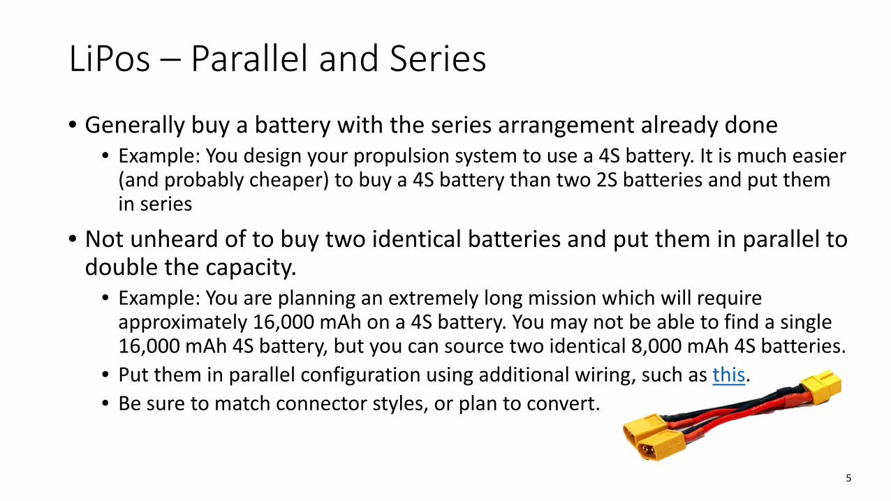
• Not unheard of to buy two identical batteries and put them in parallel to double the capacity.
• Example: You are planning an extremely long mission which will require approximately 16,000 mAh on a 4S battery. You may not be able to find a single 16,000 mAh 4S battery, but you can source two identical 8,000 mAh 4S batteries.
• Put them in parallel configuration using additional wiring, such as this.• Be sure to match connector styles, or plan to convert.
5
Batteries – Common issues/FAQs• Voltages for LiPos are given as a nominal voltage, 3.7V, which is the
voltage at approximately 50% charge• Never discharge a LiPo below 3V/cell
• Example: Absolute minimum on a 4S would be 12.0V• “We just want to fly another minute” is a bad excuse
• “The wires for this battery are huge, but I want to solder on an XT60.”• You probably purchased a high-discharge rated battery than can handle 120+
amps…there is a good reason the wires are large. Solder on an XT90 and then make or buy a XT90 to XT60 adapter.
• “How do we know how much battery we used?”• Most chargers will read out the mAh charged back into the battery• Log the mAh consumed within your Pixhawk, the save out the log file
6
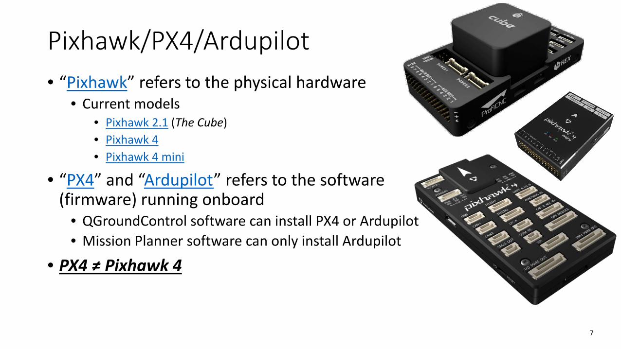
Pixhawk/PX4/Ardupilot• “Pixhawk” refers to the physical hardware
• Current models• Pixhawk 2.1 (The Cube)• Pixhawk 4• Pixhawk 4 mini
• “PX4” and “Ardupilot” refers to the software (firmware) running onboard
• QGroundControl software can install PX4 or Ardupilot• Mission Planner software can only install Ardupilot
• PX4 ≠ Pixhawk 4
7

Powering your Pixhawk
• Different models have slightly different power connectors, but should come with the correct items to connect to a LiPo battery
• Pixhawk 2 has a “power module” that sits between your LiPo and your ESC• Comes pre-installed with XT60s• Also measures battery voltage and current draw
• Nice to monitor for mission duration and battery health
• Pixhawk 4 has options1. A huge, annoying power distribution/IO board that is great for quad- and octo-copters2. In-line power module and compact IO breakout (please buy this)
8
Pixhawk – Common issues/FAQs• The connectors are delicate – be nice• Be mindful of board orientation and mounting• Remember that wires take up space
• And have non-zero weight
• Purchase 915 MHz radios, not 433 MHz• “The GCS says the battery is too low.”
• Make sure the power module is properly set up in your GCS
• “There is no signal to the servos.”• Make sure the safety switch has been pressed (aka vehicle is “unsafe”)• Make sure the servos are plugged in to the right location• Make sure the flight mode is set to your desired mode
9
Servos
• Defining specification is torque• Determining your torque requirement is not straightforward
• Depends on aerodynamic loads, hinge axis alignment, manufacturing errors, etc.
• LOTS of manufacturers to choose from• Lots of shapes and sizes
• Thin servos might be nice for wings, but probably costs more than a similarly-torque-spec’d “standard” looking model
• Make sure their required voltage is being met• More and more “HV” or High Voltage servos on the market that require more
than 6 volts, which is the highest that many ESC-borne BECs will do• Too low of a voltage can lead to an odd twitch
10
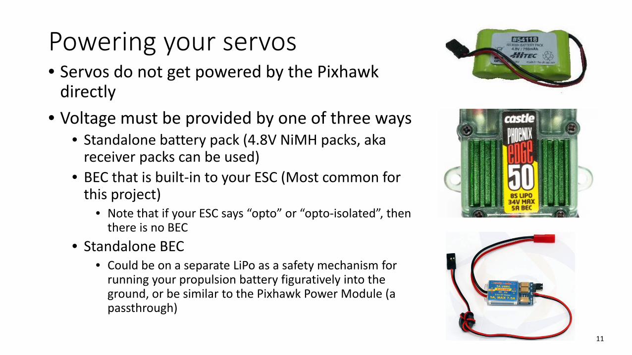
Powering your servos• Servos do not get powered by the Pixhawk
directly• Voltage must be provided by one of three ways
• Standalone battery pack (4.8V NiMH packs, aka receiver packs can be used)
• BEC that is built-in to your ESC (Most common for this project)
• Note that if your ESC says “opto” or “opto-isolated”, then there is no BEC
• Standalone BEC• Could be on a separate LiPo as a safety mechanism for
running your propulsion battery figuratively into the ground, or be similar to the Pixhawk Power Module (a passthrough)
11
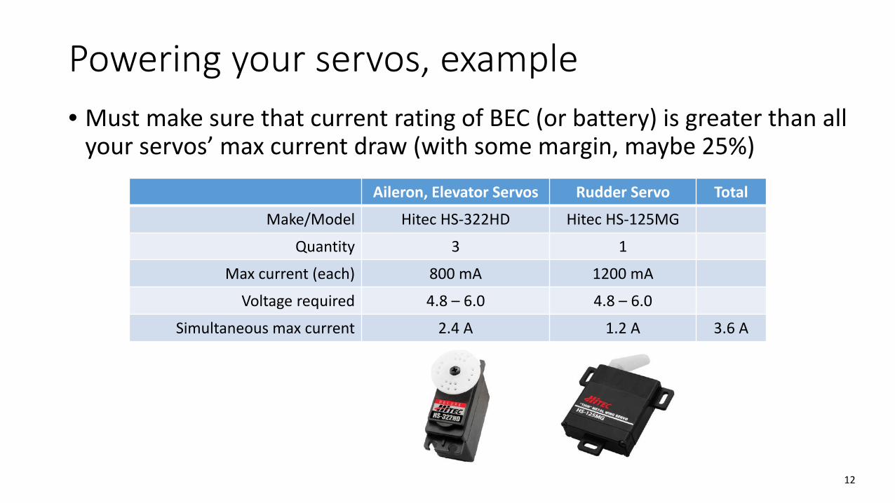
Powering your servos, example• Must make sure that current rating of BEC (or battery) is greater than all
your servos’ max current draw (with some margin, maybe 25%)
12
Aileron, Elevator Servos Rudder Servo Total
Make/Model Hitec HS-322HD Hitec HS-125MG
Quantity 3 1
Max current (each) 800 mA 1200 mA
Voltage required 4.8 – 6.0 4.8 – 6.0
Simultaneous max current 2.4 A 1.2 A 3.6 A

Positive, Negative, and SignalWhite/Yellow/Orange: PWM Signal Red: +VDC Black/Brown: -VDC
Servo signal: Pulse Width Modulation• 0% deflection: 1100 μs (Note, this can sometimes be reduced to 1000 μs)• 50% deflection (“centered”): 1500 μs• 100% deflection: 1900 μs (Note, this can sometimes be increased to 2000 μs)
13
RIGHT WRONG
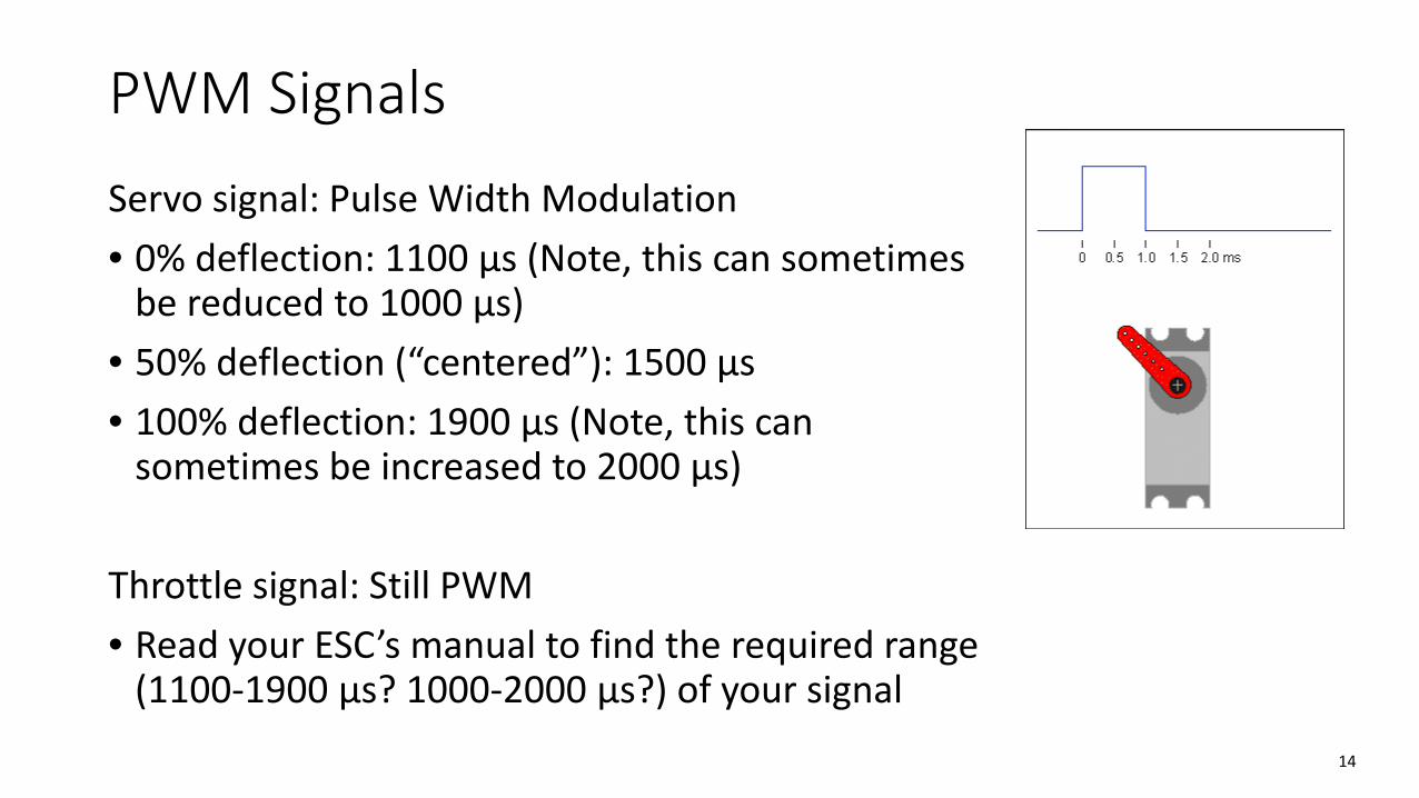
PWM SignalsServo signal: Pulse Width Modulation• 0% deflection: 1100 μs (Note, this can sometimes
be reduced to 1000 μs)• 50% deflection (“centered”): 1500 μs• 100% deflection: 1900 μs (Note, this can
sometimes be increased to 2000 μs)
Throttle signal: Still PWM• Read your ESC’s manual to find the required range
(1100-1900 μs? 1000-2000 μs?) of your signal14
Controls Mixing• Can “mix” transmitter controls to do more complex tasks automatically
• Examples• Deflect elevator up when flaps deployed• Add right rudder when throttle increased• Add elevator up when throttle increased (for planes with high-mounted motor)• Add left/right rudder to counteract adverse yaw in left/right bank
• Reduces pilot workload• May be absolutely required in a situation such as a v-tail• Note that when moving to automated flight modes, the mixing will
probably be ignored, but compensated for by the autopilot anyhow
15

Controls Mixing – RC Transmitter (Tx)• Read each transmitter’s instructions
• Example: Spektrum radios; Enter menu → Mixing → Set mixes 1 – 3
• Flaps mixes (e.g. to deflect elevator) done in the Flaps System menu• This image shows a transmitter with a 3-position switch used for
flaps (normal)• Make sure deflections are in the correct direction
• Don’t want elevator down when flaps deploy, or else you’re going down REALLY fast
• For V-tail• Glider this fall (no Pixhawk); Set up the Tx with native v-tail
mixing (usually in wing/tail setup menu or similar) or use a standalone v-tail mixer.
• With Pixhawk; Do not use Tx v-tail mixing. Re-assign servo outputs for elevator/rudder as left and right v-tails 16
Servos – Common issues/FAQs• Make sure your servos are being powered by an appropriate source
• Example of good setup: 5V, 5A BEC powering normal-sized servos• Example of bad setup: 5V, 2A BEC powering normal sized servos
• Leads to voltage sag, possibly brown-outs
• Make sure your servos are centered when installing them• Example: You take servos straight out of the box, put a servo horn
perpendicular to the flat side, and put it in your wing. You power on the servo, and send it a 1500 μs signal. It deflects 45°, and now you must uninstall the servo, move the horn, and reinstall the servo.
• “My servo is deflecting the wrong way.” (Looking like flaps instead of ailerons)
• More of an issue when using a servo “Y” cable and a low-channel receiver• If plugged into its own channel in the Pixhawk, reverse that output• Some digital servos can be reversed on the servo, but analog servos can not. 17
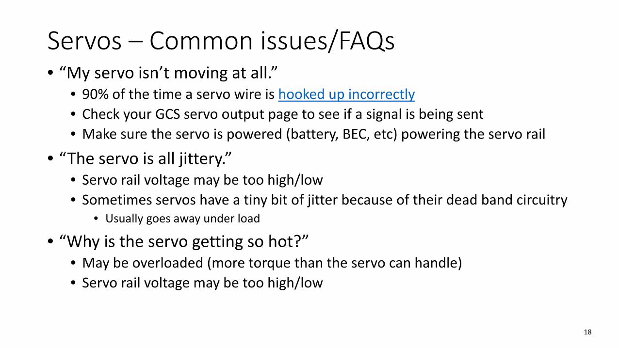
Servos – Common issues/FAQs• “My servo isn’t moving at all.”
• 90% of the time a servo wire is hooked up incorrectly• Check your GCS servo output page to see if a signal is being sent• Make sure the servo is powered (battery, BEC, etc) powering the servo rail
• “The servo is all jittery.”• Servo rail voltage may be too high/low• Sometimes servos have a tiny bit of jitter because of their dead band circuitry
• Usually goes away under load
• “Why is the servo getting so hot?”• May be overloaded (more torque than the servo can handle)• Servo rail voltage may be too high/low
18
Suggestions
• Read your product manuals• Or at least skim the important parts• Valuable tidbits like “How to hook everything up”
• Set up an “iron bird”• Basic testbed for your electronics, mounted to one piece of material so you can
carry it around• Can include Pixhawk, servos, batteries, GPS, etc.• Can make it in 5 minutes out of foamboard and tape – it need not be pretty
• Try to have access to a digital multimeter• Best basic electrical troubleshooting tool
• Voltage testing• Continuity testing
19
Suggestions
• List out all electrical connections before you purchase components• Figure out if you need to replace a battery, ESC connector, etc.• Figure out if you need to buy different size bullet connectors for your motor/ESC
• Build an electrical budget (for power draw, not $$)• Investigate whether any additional systems will require separate power sources
due to voltage differences or system architecture reasons
• Produce a nice (high quality) and easy-to-follow electrical diagram• Include cable and connector types, peripherals, what power is going where, etc.• Does not need to be analogous to the aircraft layout, but it can be
20
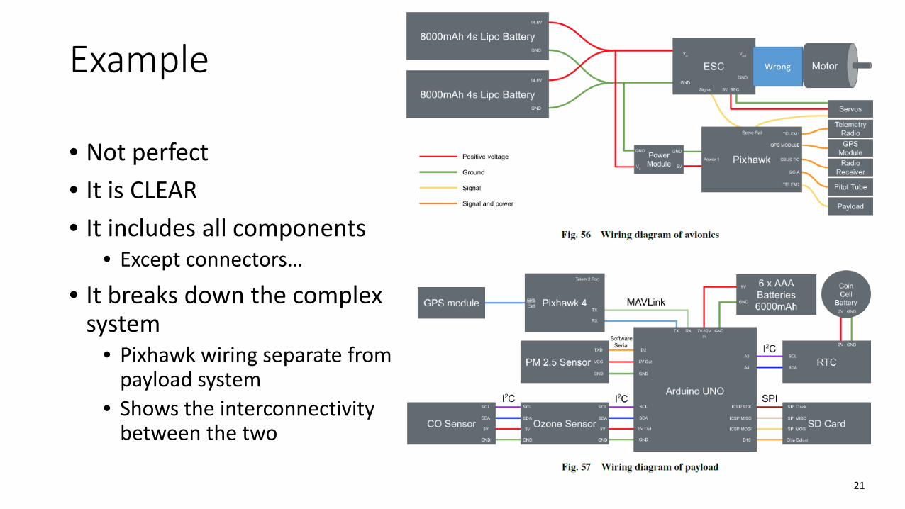
Example
• Not perfect• It is CLEAR• It includes all components
• Except connectors…
• It breaks down the complex system
• Pixhawk wiring separate from payload system
• Shows the interconnectivity between the two
21
Wrong