PINSTECH-199 Radiation Dose Reduction by Water Shield
32
PINSTECH-199 Radiation Dose Reduction by Water Shield (W-Shielder Manual) Jahan Zeb Waheed Arshed S. Salman Ahmad Health Physics Division Directorate of Systems & Services Pakistan Institute of Nuclear Science & Technology P. O. Nilore, Islamabad, Pakistan [email protected]
Transcript of PINSTECH-199 Radiation Dose Reduction by Water Shield
PINSTECH-199
Radiation Dose Reduction by Water
Shield
(W-Shielder Manual)
Jahan Zeb Waheed Arshed
S. Salman Ahmad
Health Physics Division Directorate of Systems & Services
Pakistan Institute of Nuclear Science & Technology P. O. Nilore, Islamabad, Pakistan
CONTENTS
Page
ABSTRACT 01 1. INTRODUCTION 02 2. RADIATION SHIELDING 02
3. INTERACTION OF γ RADIATION WITH MATTER 02
3.1 Photo Electric Effect 03 3.2 Compton Effect (γ ray Scattering) 03 3.3 Pair Production 04
4. ATTENUATION OF γ RADIATION IN MATTER 06 4.1 Narrow Beam Geometry 06 4.2 Broad Beam Attenuation 07 4.3 Homogeneous Media 08 4.4 Buildup Factor: the basic idea 09 4.5 Buildup Factor: A more general approach 10 4.6 Empirical Formulae for B(μr) 13
(i) Linear formula 14 (ii) Berger’s formula 14 (iii) Capo’s formula 14 (iv) Taylor’s formula 14
5. THEORY BEHIND W-SHIELDER 15 6. HOW DOES THE SOFTWARE WORK 16 7. HOW TO OPERATE THE SOFTWARE 16 8. ATTENUATION FACTOR TABLE 21 9. REFERENCES 27 10. BIBLIOGRAPHY OF W-SHIELDER (SOFTWARE) 28
2
LIST OF TABLES Table 1: Exposure Buildup Factor for Isotropic Point Source in an
Infinite Medium.
23 Table 2: Energy Deposition Buildup Factor for Isotropic Point Source
in Infinite Medium.
24 Table 3: The mass attenuation coefficient (μ/ρ)for water 25 Table 4: Parameters for Taylor form of the exposure build-up factor
for point isotropic source for water. 25
Table 5: Calculated thickness (cm) of Water (density=1 g. cm-3) for different attenuation factor and γ rays energies with the help of “W-Shielder” programme.
26
1
ABSTRACT
This report is an operational manual of shielding software “W-Shielder”, developed at Health Physics Division (HPD), Pakistan Institute of Nuclear Science & Technology (PINSTECH), Pakistan Atomic Energy Commission. The software estimates shielding thickness for photons having their energy in the range 0.5 to 10 MeV. To compute the shield thickness, self absorption in the source has been neglected and the source has been assumed as a point source. Water is used as a shielding material in this software. The software is helpful in estimating the water thickness for safe handling, storage of gamma emitting radionuclide(s).
2
1. INTRODUCTION
Electromagnetic radiation possesses greater power of penetration than other nuclear radiation except neutrons. When gamma radiation passes through matter, their intensity decreases due to interactions with the matter, such as photoelectric effect, Compton effect, pair production and photonuclear reactions. Use of matter to reduce the intensity of gamma radiation is known as shielding. The effectiveness of shield depends upon the energy of the radiation, thickness and type of the shielding material. The higher the atomic number and the density of the shielding material the more effective it is in reducing the intensity of gamma radiation. In computing, the shield thickness, it has been assumed that the radiation source is a point source. It is possible to treat a line-source or other large radiation source as a point source if the distance from it amounts to more than twice the maximum of its extension. In this case, the highest theoretical deviation is about 4 % when computing the dose rate. [1-3]. This report discusses computer software “W-Shielder” developed in C++, which estimates the water thickness for shielding gamma radiation sources [4]. The software is helpful in designing shields and containers for safe handling and storage of gamma emitting radioactive materials such as spent fuel. The energy range of the photons considered is 0.5 to10 MeV. 2. RADIATION SHIELDING
Gamma radiation shielding is the absorption and attenuation of gamma energy in shielding material. Most materials absorb the energy of gamma rays to some extent. The extent of attenuation depends on the density and thickness of the shielding material. A useful measure of shielding property is the mass per unit area of material. Hence a thick layer of a lighter material will have the same effect as a thin layer of a denser material. Radiation Shielding is used to reduce the radiation exposure to personnel and equipment in the vicinity of radiation sources. It is called biological and thermal shielding, respectively.
3. INTERACTION OF γ RADIATION WITH MATTER Although more than ten distinctive elementary processes have been identified
by which gamma rays interact with matter, for the purposes of radiation shielding, there are only three that are of any significance. These are:
(i) The Photoelectric Effect ( peσ ) (ii) Compton Scattering ( Cσ ) (iii) Electron-Positron Pair Production ( PPσ ) The principal interaction processes for γ radiation in the range 0.1-10 MeV
that are responsible for their attenuation are briefly given below.

3
3.1 Photo Electric Effect. In this effect the incident photons disappears and an orbital electron is ejected
from the atom. The electron carries away all the energy of the photon minus the binding (ionization) energy of the electron in the atom. This is an important mode of interaction for low energy photons in materials with high atomic numbers. The process can be regarded effectively as purely absorptive, since neither the photoelectrons nor the fluorescent radiation released as a consequence of photoelectric effect have sufficient energy to warrant independent study in shield analysis. The photoelectric cross-section depends strongly on Z, varying as
peμ ~ Zn
where n is the function of E. Because of the strong dependence of peμ on Z, the photoelectric effect is of greatest importance for the heavier atom such as lead, especially at lower energies [5].
Fig. 1. Schematic diagram of the Photoelectric effect. The incident photon is ‘destroyed’.
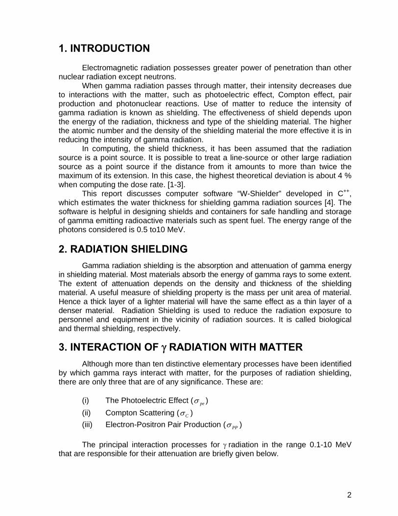
3.2 Compton Scattering In this process a photon collides with an atomic electron loses some of its
energy and is deflected from its original direction. It has an effect on the incident photon that is somewhat analogous to the effect that elastic scattering by an atomic nucleus has on a neutron – in both cases the incident particle survives the collisions. Compton scattering is the predominant reaction for gamma photons with energies in the range 1 MeV-10 MeV for elements of low and intermediate atomic numbers. The main theoretical difficulty in gamma attenuation calculation is attributable to the ramifications of multiple Compton scattering, it is, therefore, an important process in the theory of radiation shielding. The Compton cross-section per atom, Cσ , is equal to the number of electron in the atom-namely, Z-multiplied by e Cσ . Thus,
Cσ = Ze Cσ
4
Fig. 2. Schematic diagram of the Compton effect. The incident photon is survives.
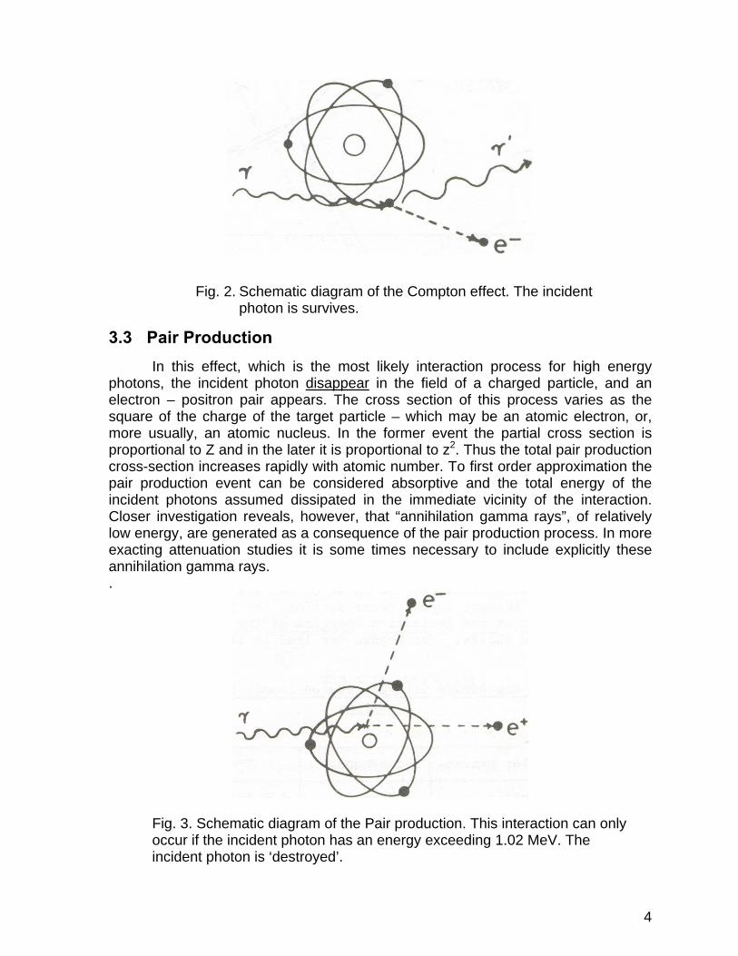
3.3 Pair Production In this effect, which is the most likely interaction process for high energy photons, the incident photon disappear in the field of a charged particle, and an electron – positron pair appears. The cross section of this process varies as the square of the charge of the target particle – which may be an atomic electron, or, more usually, an atomic nucleus. In the former event the partial cross section is proportional to Z and in the later it is proportional to z2. Thus the total pair production cross-section increases rapidly with atomic number. To first order approximation the pair production event can be considered absorptive and the total energy of the incident photons assumed dissipated in the immediate vicinity of the interaction. Closer investigation reveals, however, that “annihilation gamma rays”, of relatively low energy, are generated as a consequence of the pair production process. In more exacting attenuation studies it is some times necessary to include explicitly these annihilation gamma rays. .
Fig. 3. Schematic diagram of the Pair production. This interaction can only occur if the incident photon has an energy exceeding 1.02 MeV. The incident photon is ‘destroyed’.

5
The total photon cross section per atom is obtained as the sum of these three partial cross sections, and we may write
PPCpe σσσσ ++= and therefore, using an obvious notation,
ρμ
ρμ
ρμ
ρμ PPCpe ++=
and
PPCpe μμμμ ++=
Fig. 4. Relative importance of the three major types of gamma-ray interaction.
Fig. 4 shows the relative importance for the three major types of gamma-ray interaction. The lines show the value of Z and hν for which the two neighboring effects are just equal [6].
6
4. ATTENUATION OF γ RADIATION IN MATTER 4.1 Narrow Beam Geometry
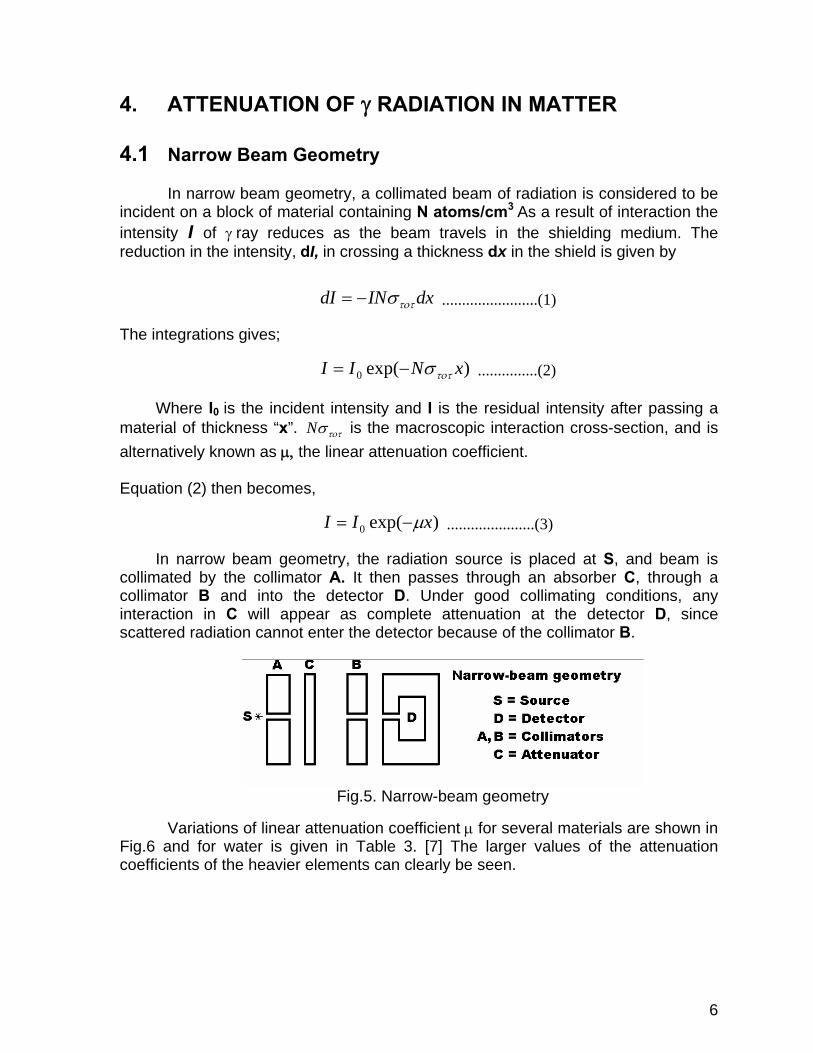
In narrow beam geometry, a collimated beam of radiation is considered to be incident on a block of material containing N atoms/cm3 As a result of interaction the intensity I of γ ray reduces as the beam travels in the shielding medium. The reduction in the intensity, dI, in crossing a thickness dx in the shield is given by
dxINdI τοτσ−= ........................(1)
The integrations gives;
)exp(0 xNII τοτσ−= ...............(2)
Where I0 is the incident intensity and I is the residual intensity after passing a
material of thickness “x”. τοτσN is the macroscopic interaction cross-section, and is alternatively known as μ, the linear attenuation coefficient. Equation (2) then becomes,
)exp(0 xII μ−= ......................(3)
In narrow beam geometry, the radiation source is placed at S, and beam is collimated by the collimator A. It then passes through an absorber C, through a collimator B and into the detector D. Under good collimating conditions, any interaction in C will appear as complete attenuation at the detector D, since scattered radiation cannot enter the detector because of the collimator B.
Fig.5. Narrow-beam geometry
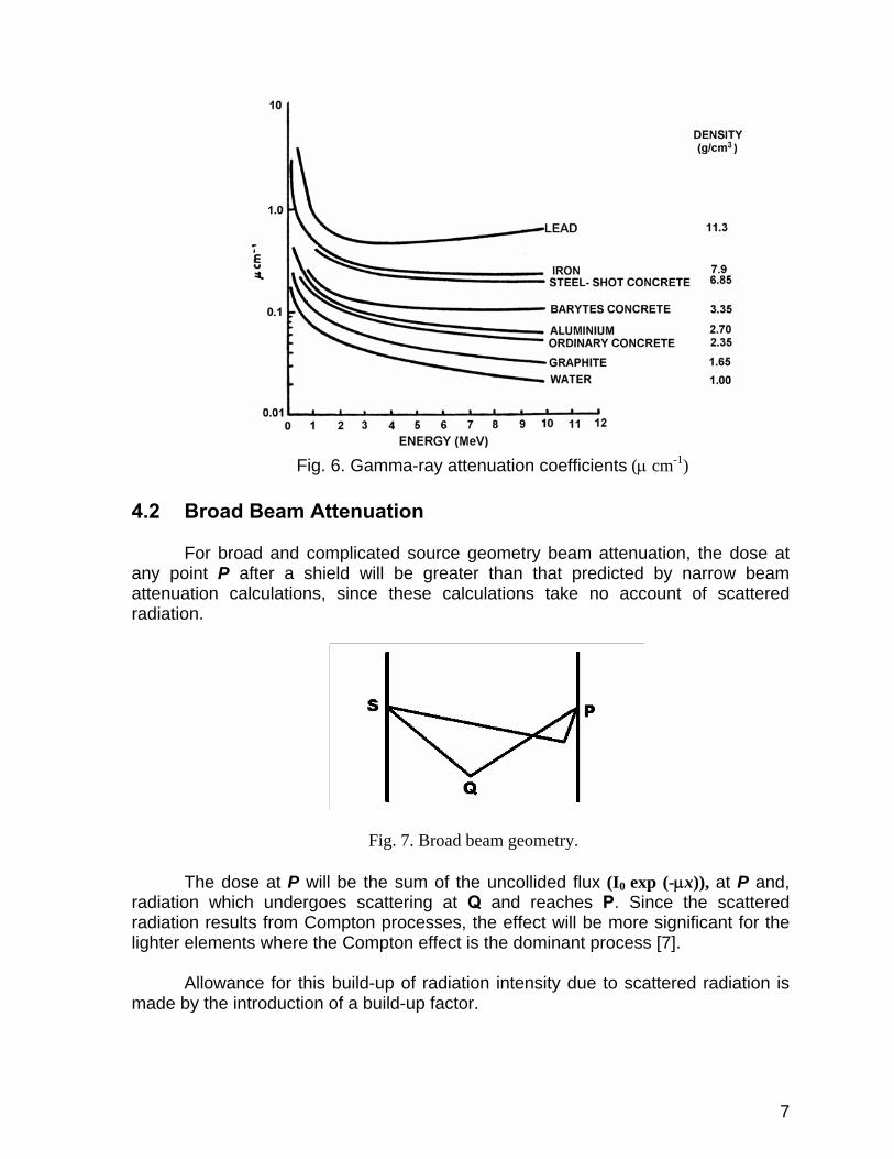
Variations of linear attenuation coefficient μ for several materials are shown in Fig.6 and for water is given in Table 3. [7] The larger values of the attenuation coefficients of the heavier elements can clearly be seen.
7
Fig. 6. Gamma-ray attenuation coefficients (μ cm-1)
4.2 Broad Beam Attenuation
For broad and complicated source geometry beam attenuation, the dose at any point P after a shield will be greater than that predicted by narrow beam attenuation calculations, since these calculations take no account of scattered radiation.
Fig. 7. Broad beam geometry.
The dose at P will be the sum of the uncollided flux (I0 exp (-μx)), at P and, radiation which undergoes scattering at Q and reaches P. Since the scattered radiation results from Compton processes, the effect will be more significant for the lighter elements where the Compton effect is the dominant process [7].
Allowance for this build-up of radiation intensity due to scattered radiation is
made by the introduction of a build-up factor.
8
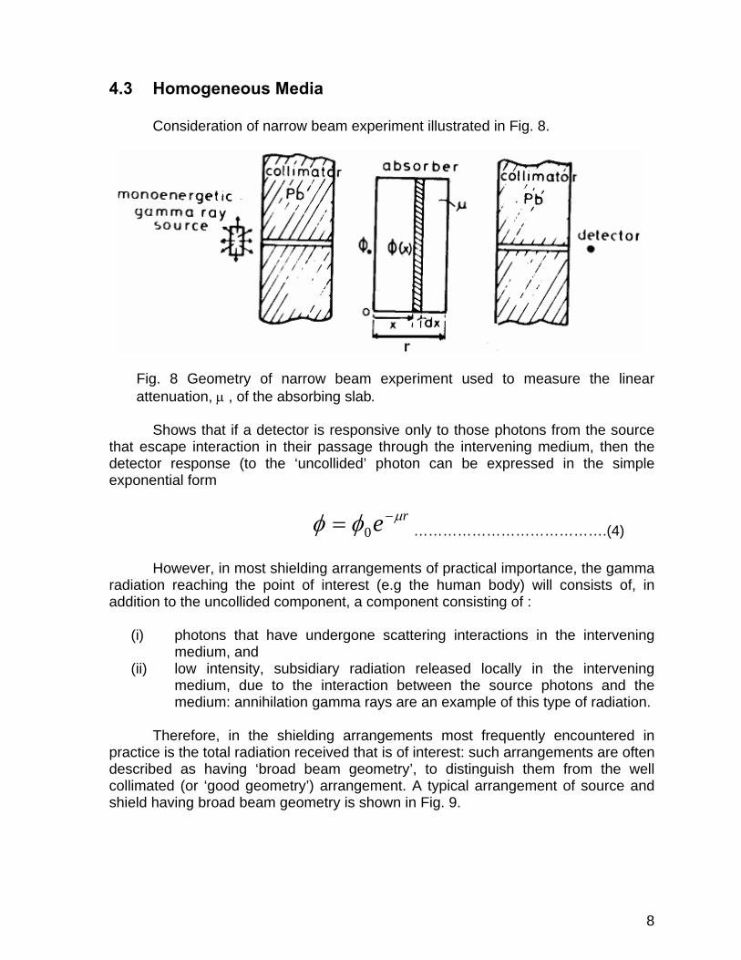
4.3 Homogeneous Media
Consideration of narrow beam experiment illustrated in Fig. 8.
Fig. 8 Geometry of narrow beam experiment used to measure the linear attenuation, μ , of the absorbing slab.
Shows that if a detector is responsive only to those photons from the source
that escape interaction in their passage through the intervening medium, then the detector response (to the ‘uncollided’ photon can be expressed in the simple exponential form
re μφφ −= 0 ………………………………….(4)
However, in most shielding arrangements of practical importance, the gamma
radiation reaching the point of interest (e.g the human body) will consists of, in addition to the uncollided component, a component consisting of :
(i) photons that have undergone scattering interactions in the intervening medium, and
(ii) low intensity, subsidiary radiation released locally in the intervening medium, due to the interaction between the source photons and the medium: annihilation gamma rays are an example of this type of radiation.
Therefore, in the shielding arrangements most frequently encountered in
practice is the total radiation received that is of interest: such arrangements are often described as having ‘broad beam geometry’, to distinguish them from the well collimated (or ‘good geometry’) arrangement. A typical arrangement of source and shield having broad beam geometry is shown in Fig. 9.
9
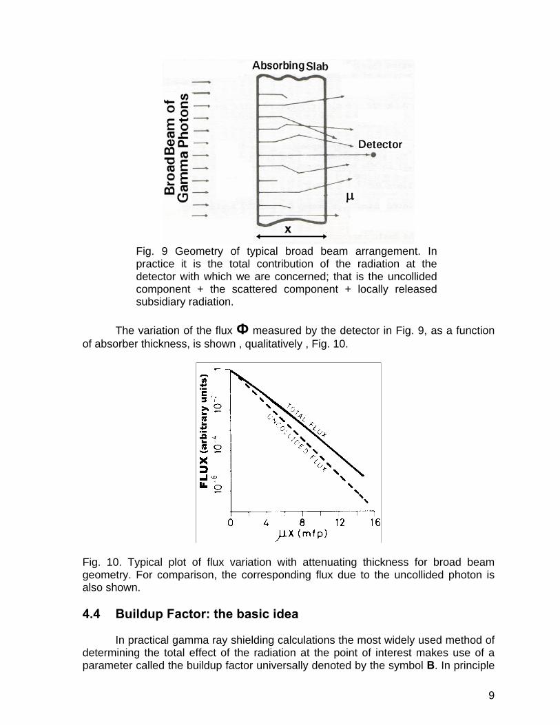
Fig. 9 Geometry of typical broad beam arrangement. In practice it is the total contribution of the radiation at the detector with which we are concerned; that is the uncollided component + the scattered component + locally released subsidiary radiation.
The variation of the flux Ф measured by the detector in Fig. 9, as a function of absorber thickness, is shown , qualitatively , Fig. 10.
Fig. 10. Typical plot of flux variation with attenuating thickness for broad beam geometry. For comparison, the corresponding flux due to the uncollided photon is also shown. 4.4 Buildup Factor: the basic idea In practical gamma ray shielding calculations the most widely used method of determining the total effect of the radiation at the point of interest makes use of a parameter called the buildup factor universally denoted by the symbol B. In principle

10
the buildup factor concept is also applicable to neutron attenuation, but in practice it is found to be much less successful when applied to neutrons, and consequently it is a much less important concept in the context of neutron shielding calculations. In the field of radiation shielding, unless stated otherwise, the term buildup factor can be assumed to refer to gamma radiation. Briefly, the buildup factor can be considered as a simple correction factor which adjusts the result for the uncollided photons to include the contributions from the scattered and subsidiary radiation. The advantage of such a simple device is easily demonstrated. Let us take as a simple example, the calculation of the flux due to a monoenergetic unit points source of gamma rays at a point distance r in an absorbing medium. Here, for the sake of clarity in describing quantities of immediate concern, we use such terms as “point source” and “detector response” rather loosely, and rely on the reader’s intuitive understanding. The flux due to those photons that have penetrated the intervening material without suffering a collision, i.e. the unclouded flux, can be expressed immediately as
24 re r
u πφ
μ−
= ……………………………………..(5)
Now, assuming for the moment we know the values of the appropriate buildup factor B, we can readily write down the corresponding result for the total flux at r, as
24 rBeB
r
u πφφ
μ−
== …………………………………(6)
In this way, we augment the effect of the uncollided photons to include the
contributions from those photons that have undergone interactions in the surrounding medium, such as Compton scatterings, but have not been effectively ‘removed ‘from the source radiation. Moreover, the formalism is such that what is intrinsically a formidable problem in particle transport theory, is reduced to the problem of obtaining the appropriate vale of the buildup factor B. Note that in eq.(6), μ , is the usual narrow beam linear attenuation coefficient. In practical terms, the value of B is obtained from the basic buildup data tables provided in shielding manuals. These basic data are mostly those of Goldstein and Wilkins [8] who used the moments method of solving the Boltzmann transport equation to derive extensive sets of buildup factor data for most materials of interest in shielding applications. 4.5 Buildup Factor: A more general approach In shielding calculations there are other quantities of interest than the particle flux density, for example dose rate, and it is desirable to generalize the concept of buildup factor to include any quantity that can be measured by a detector. It is apparent from eq.(6) that B is the ratio of broad beam flux to the narrow beam flux.
11
We can utilize this relationship to extend the application of buildup factor, and define the buildup factor generally by;
detector response to the radiation at the point of interest
B
= detector response to the uncollided radiation at the same point
The buildup factor is defined with respect to a monoenergetic-source and a detector situated in an infinite homogeneous medium. Theoretical investigation shows that the value of B depends on the following conditions:
(i) The nature of the attenuating medium (i.e. the atomic number, Z) (ii) The energy of the source photons. (iii) The distance, in mean free paths, between the source and point of
interest. (iv) The geometry of the source. (v) The quantity being considered.
In view of this, the functional dependence of B can be expressed as
B (Z, EO, μr)
where Z is the atomic number of the attenuating medium EO is the energy of the monoenergetic source μr is the attenuating thickness of the intervening medium, in
units of mean free path (mfp) of photons with energy EO.
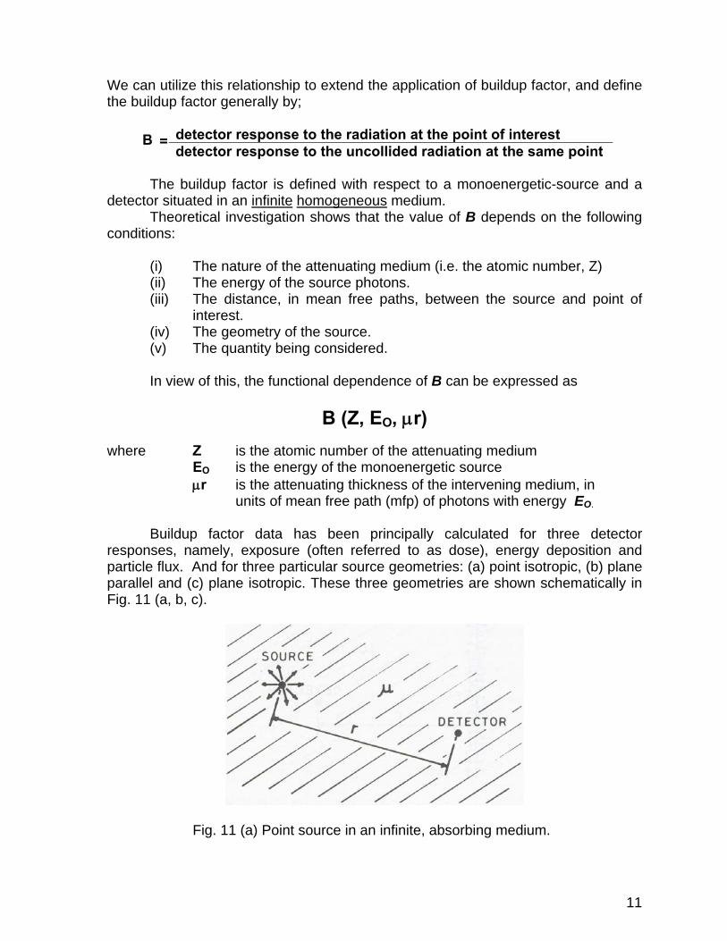
Buildup factor data has been principally calculated for three detector responses, namely, exposure (often referred to as dose), energy deposition and particle flux. And for three particular source geometries: (a) point isotropic, (b) plane parallel and (c) plane isotropic. These three geometries are shown schematically in Fig. 11 (a, b, c).
Fig. 11 (a) Point source in an infinite, absorbing medium.
12
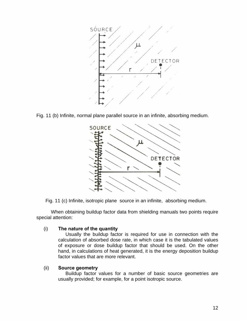
Fig. 11 (b) Infinite, normal plane parallel source in an infinite, absorbing medium.
Fig. 11 (c) Infinite, isotropic plane source in an infinite, absorbing medium.
When obtaining buildup factor data from shielding manuals two points require special attention:
(i) The nature of the quantity Usually the buildup factor is required for use in connection with the calculation of absorbed dose rate, in which case it is the tabulated values of exposure or dose buildup factor that should be used. On the other hand, in calculations of heat generated, it is the energy deposition buildup factor values that are more relevant.
(ii) Source geometry
Buildup factor values for a number of basic source geometries are usually provided; for example, for a point isotropic source.
13
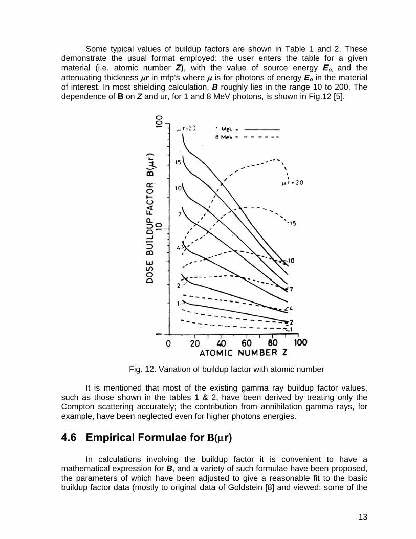
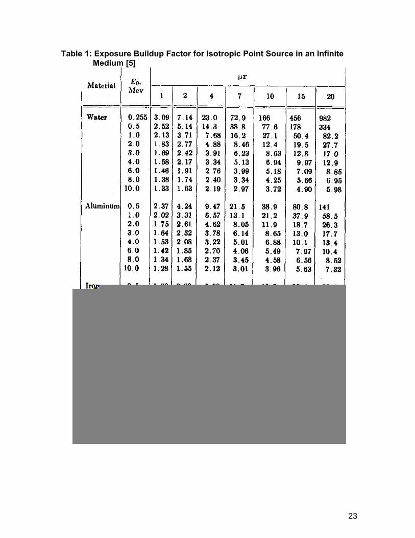
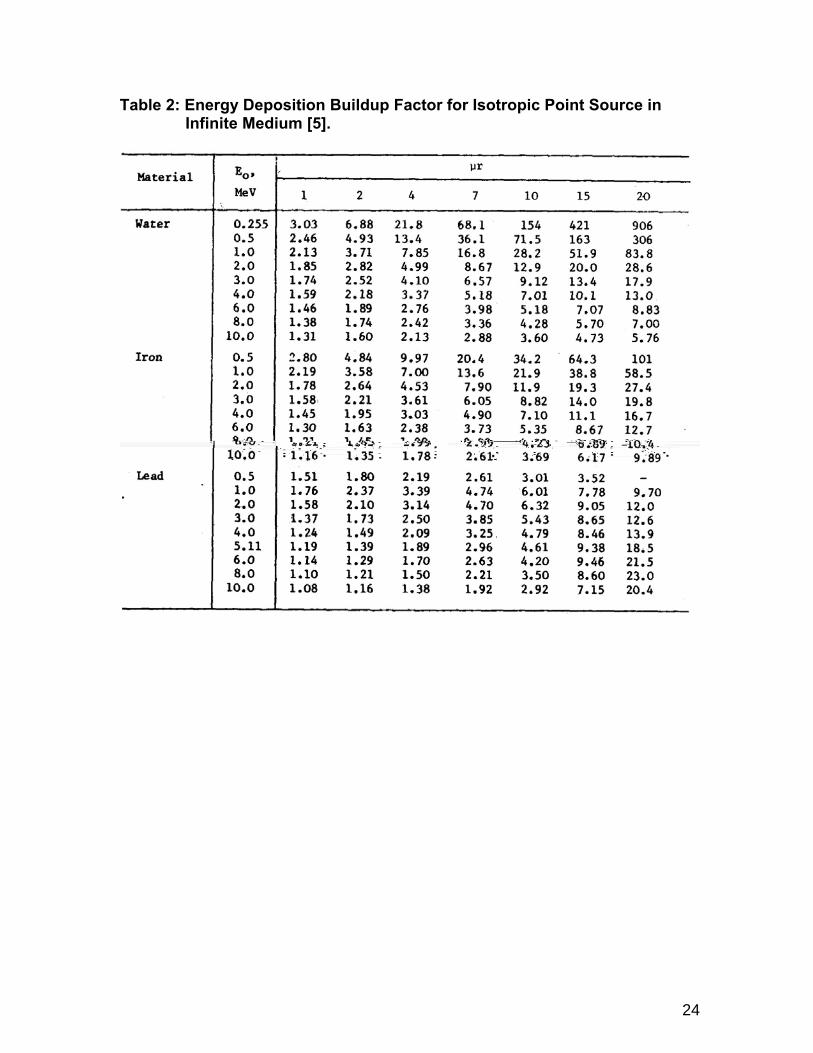
Some typical values of buildup factors are shown in Table 1 and 2. These demonstrate the usual format employed: the user enters the table for a given material (i.e. atomic number Z), with the value of source energy Eo, and the attenuating thickness μr in mfp’s where μ is for photons of energy Eo in the material of interest. In most shielding calculation, B roughly lies in the range 10 to 200. The dependence of B on Z and ur, for 1 and 8 MeV photons, is shown in Fig.12 [5].
Fig. 12. Variation of buildup factor with atomic number
It is mentioned that most of the existing gamma ray buildup factor values,
such as those shown in the tables 1 & 2, have been derived by treating only the Compton scattering accurately; the contribution from annihilation gamma rays, for example, have been neglected even for higher photons energies.
4.6 Empirical Formulae for B(μr)
In calculations involving the buildup factor it is convenient to have a
mathematical expression for B, and a variety of such formulae have been proposed, the parameters of which have been adjusted to give a reasonable fit to the basic buildup factor data (mostly to original data of Goldstein [8] and viewed: some of the

14
more commonly used of these formulae are now briefly reviewed; a more extensive survey is given by Trubey [9]). (i) Linear formula
)(1)( rkrB μμ += if rμ =1 then the value of constant k will be
1)1( += Bk
This is one of the simplest, and least accurate, approximations. It should not be used for thick shields. Its principal usefulness is didactic: for example in demonstrating the procedure for and effect of incorporating the buildup factor into shielding calculations. (ii) Berger’s formula
)exp(1)( rbrarB μμμ += This formulation strikes a good balance between accuracy and computing complexity. (iii) Capo’s formula
∑ ==
3
0i
i r)(),(io rEB μβμ
Where
∑ ==
4
0)1(
jj
oiji E
Cβ
(iv) Taylor’s formula
)exp()1()exp( 21 xAxAB μαμα −−+−= The coefficient A, α1 and α2 in the preceding formulae is readily found in the
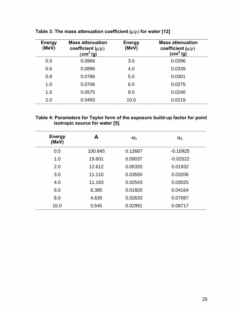
various shielding manuals [10], and in Schaeffer [11]. Some values of the Taylor coefficients are given in Table 4. Caop’s formula, although not particularly
15
convenient for mathematical working, has the advantage of being more general in as much as the source energy, Eo, is included as a variable: the other formulae require a different set of coefficients, or parameters, for each value of Eo. Perhaps the most widely used is Taylor’s formulation, as it lends itself to analytical integration in subsequent mathematical manipulation. Of course, the more complex the mathematical expression assumed for B, the better is the fit obtained to the original data over a wide range of μr. But if mathematical form is more complex than, say Taylor’s, it makes subsequent analytical solutions difficult to drive. 5. THEORY BEHIND W-SHIELDER
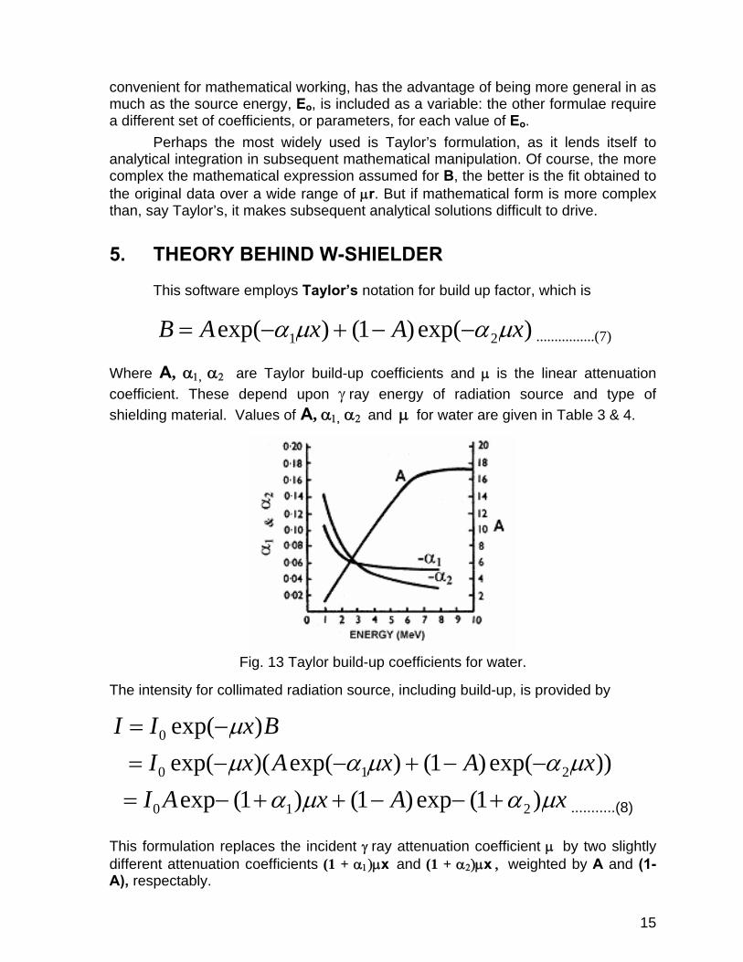
This software employs Taylor’s notation for build up factor, which is
)exp()1()exp( 21 xAxAB μαμα −−+−= ................(7) Where A, α1, α2 are Taylor build-up coefficients and μ is the linear attenuation coefficient. These depend upon γ ray energy of radiation source and type of shielding material. Values of A, α1, α2 and μ for water are given in Table 3 & 4.
Fig. 13 Taylor build-up coefficients for water.
The intensity for collimated radiation source, including build-up, is provided by
BxII )exp(0 μ−=
))exp()1()exp()(exp( 210 xAxAxI μαμαμ −−+−−=
xAxAI μαμα )1(exp)1()1(exp 210 +−−++−= ...........(8) This formulation replaces the incident γ ray attenuation coefficient μ by two slightly different attenuation coefficients (1 + α1)μx and (1 + α2)μx , weighted by A and (1-A), respectably.
16
The expression obtained for the flux with build-up is thus very similar to that for the uncollided flux, I0 exp (-μ x), with slightly modified exponents and weighting factors.
6. HOW DOES THE SOFTWARE WORK • By selecting any given radionuclide or entering energy in the “Main Menu”,
software interpolates the value of μ, A, α1 & α2 for water against the given energy by using the parameters of Taylor build-up coefficients, as given in Table 3 & 4. These coefficients have already been fed in the software.
• Software takes the value of I0 from “Activity-Doserate Menu” and “Reduced Doserate Menu” and then equates the eq. 9 to “1”.
))1(exp)1()1(exp(/1 210 xAxAII μαμα +−−++−= …(9)
• Software assumes the value of thickness “x” as “0.01” and calculates for it. If the R.H.S is equal to or very close to “1” then it quits the calculation.
• If R.H.S is not equal or close to “1” it increases the value of thickness “x” until R.H.S comes very close to “1”.
• Software draws a cylinder in accordance with calculated thickness. • The software at the end displays a “Report” that shows the results of its
interpolation and parameters for which the thickness was calculated. • After pressing any key the software is ready to calculate shielding thickness
again or exit from it.
7. HOW TO OPERATE THE SOFTWARE. • Software consists of a single executable file “W-Shielder.exe” which can be
run both in DOS and Window environment. DOS environment:
• Copy W-Shielder.exe at your desired location i.e. C:\W-Shielder or in any other folder.
• Log into desired location and then type “W-Shielder” or otherwise A:\W-Shielder
Window environment:
• Click “Start”, select “Run” and then type “A:\W-Shielder” and then select “OK”. Title screen for W-Shielder will appear on the monitor and will disappear on pressing any key (Any key does not include all functions keys, Alt, Ctrl & Shift keys) and Main menu screen will appear on the monitor.
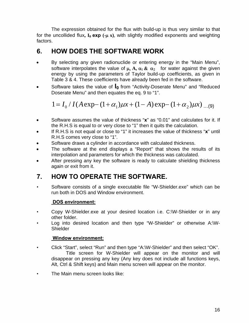
• The Main menu screen looks like:
17
• After three seconds and “pressing any key” the following “Main Menu” window will appear.
• Here the user has to select the Radionuclide by using num keys ”1”, “2”, “3”
or “4”. “0” key is used to exit from the software.
18
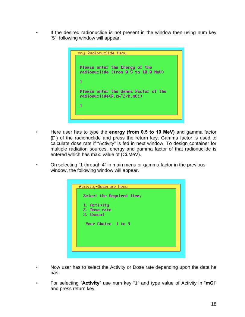
• If the desired radionuclide is not present in the window then using num key “5”, following window will appear.
• Here user has to type the energy (from 0.5 to 10 MeV) and gamma factor (Γ ) of the radionuclide and press the return key. Gamma factor is used to calculate dose rate if “Activity” is fed in next window. To design container for multiple radiation sources, energy and gamma factor of that radionuclide is entered which has max. value of (Ci.MeV).
• On selecting “1 through 4” in main menu or gamma factor in the previous window, the following window will appear.
• Now user has to select the Activity or Dose rate depending upon the data he has.
• For selecting “Activity” use num key “1” and type value of Activity in “mCi” and press return key.
19
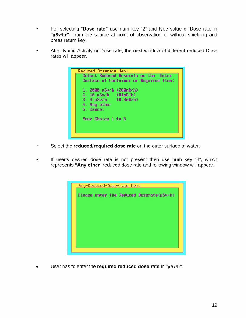
• For selecting “Dose rate” use num key “2” and type value of Dose rate in “μSv/hr” from the source at point of observation or without shielding and press return key.
• After typing Activity or Dose rate, the next window of different reduced Dose rates will appear.
• Select the reduced/required dose rate on the outer surface of water.
• If user’s desired dose rate is not present then use num key “4”, which represents “Any other” reduced dose rate and following window will appear.
• User has to enter the required reduced dose rate in “μSv/h”.
20
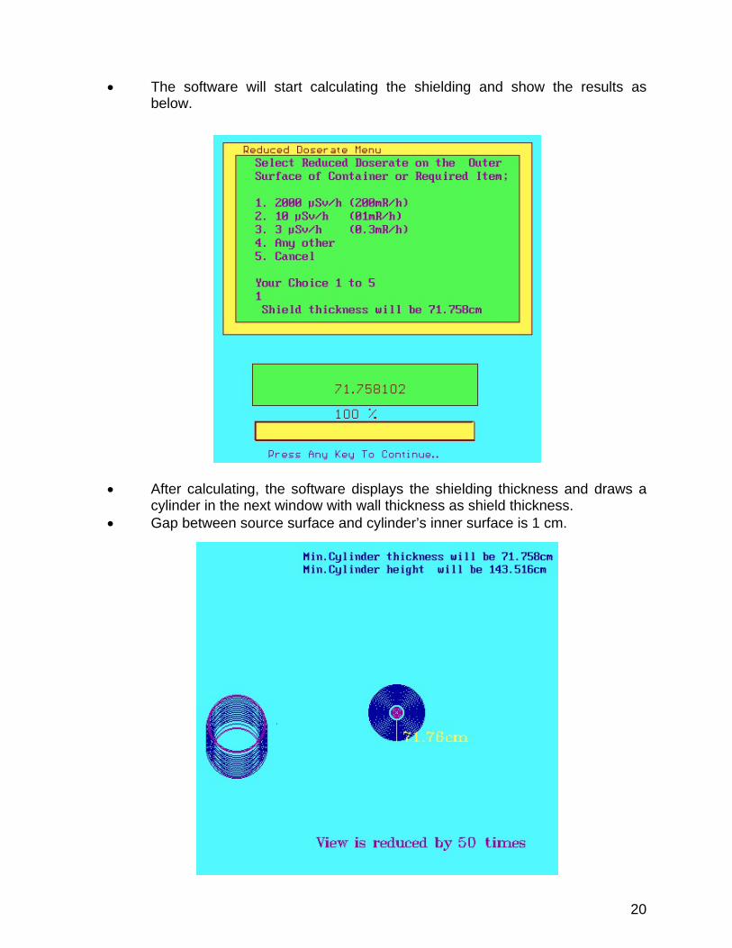
• The software will start calculating the shielding and show the results as below.
• After calculating, the software displays the shielding thickness and draws a cylinder in the next window with wall thickness as shield thickness.
• Gap between source surface and cylinder’s inner surface is 1 cm.
21
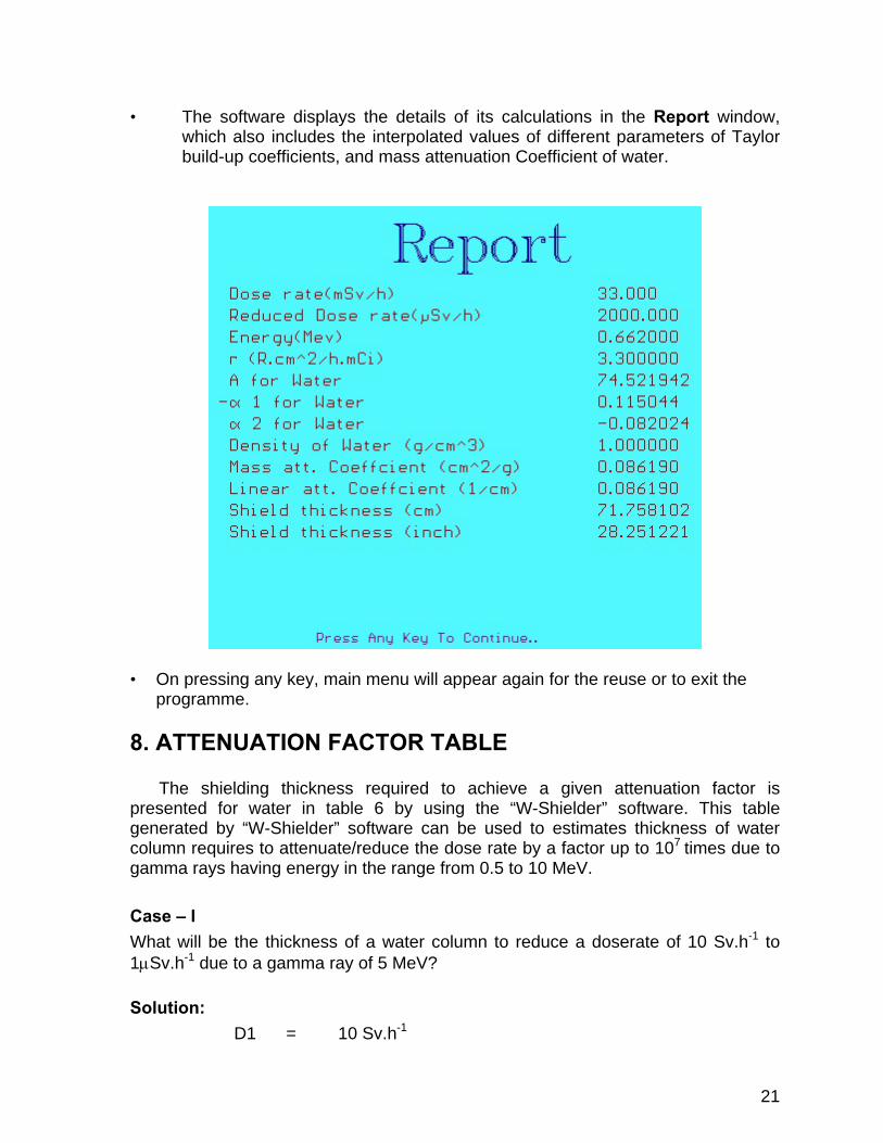
• The software displays the details of its calculations in the Report window,
which also includes the interpolated values of different parameters of Taylor build-up coefficients, and mass attenuation Coefficient of water.
• On pressing any key, main menu will appear again for the reuse or to exit the programme.
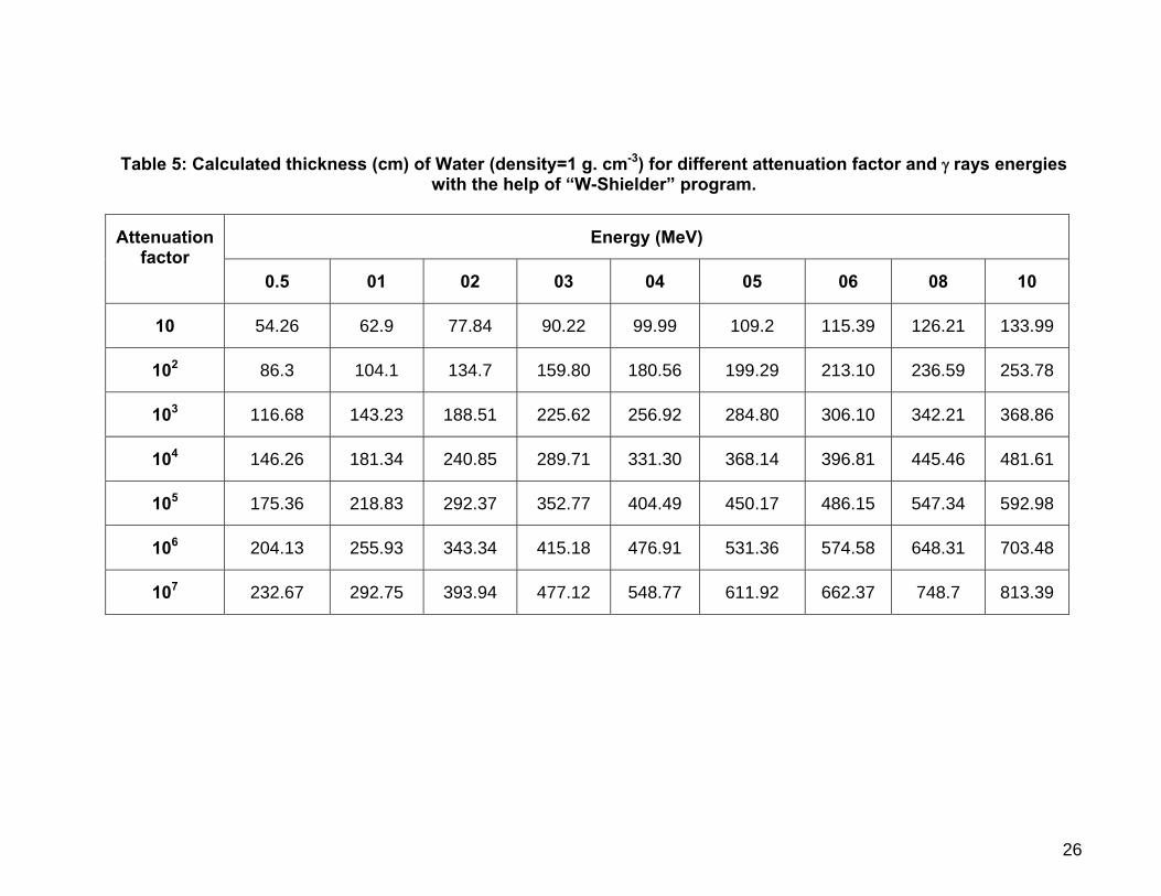
8. ATTENUATION FACTOR TABLE The shielding thickness required to achieve a given attenuation factor is presented for water in table 6 by using the “W-Shielder” software. This table generated by “W-Shielder” software can be used to estimates thickness of water column requires to attenuate/reduce the dose rate by a factor up to 107 times due to gamma rays having energy in the range from 0.5 to 10 MeV.
Case – I What will be the thickness of a water column to reduce a doserate of 10 Sv.h-1 to 1μSv.h-1 due to a gamma ray of 5 MeV?
Solution: D1 = 10 Sv.h-1

22
D2 = 1μ Sv.h-1 Attenuation Factor = D1/D2 =10 Sv.h-1/1μ Sv.h-1 = 107
So, from the table 5, column 7 for 5 MeV and row 9 for attenuation factor 107 , the thickness will be 611.92 cm.
Case – II A Co-60 source (energy of gamma radiation E = 1.25 MeV) with an activity of 775.2 Ci is to be shielded with a water column so that the doserate after shielding is 10 μSv.h-1. What will be thickness of water column? Solution: Activity = 775.2 Ci Γ = 12.9 R. cm2/h. Ci So dose rate will be = 775.2 Ci x 12.9 R. cm2.h-1. Ci-1
= 10000 R.h-1 = 100 Sv.h-1
D1 = 100 Sv.h-1 D2 = 10 μ Sv.h-1 Attenuation Factor = D1/D2 =100 Sv.h-1 /10μ Sv.h-1 = 107
Since there is no data is given for 1.25 MeV energy. So, the table will be
linearly interpolated with sufficient accuracy to estimates the thickness. For the interpolation; E = 1.25 E1 = 1 E2 = 2 T1 = 292.75(Values of thickness for 1 MeV at 107 attenuation factor) T2 = 393.94(Values of thickness for 2 MeV at 107 attenuation factor) Thickness will be = T1+ ((T2-T1)*(E-E1))/E2-E1) = 292.75 + ((393.94-292.75)*(1.25-1))/(2-1) = 318.05 cm The thickness can also be estimated from the Fig. 14 which shows the water column thickness for different gamma energies and attenuation factors.
23
Table 1: Exposure Buildup Factor for Isotropic Point Source in an Infinite Medium [5]
24
Table 2: Energy Deposition Buildup Factor for Isotropic Point Source in Infinite Medium [5].
25
Table 3: The mass attenuation coefficient (μ/ρ) for water [12]
Energy (MeV)
Mass attenuation coefficient (μ/ρ)
(cm2 /g)
Energy (MeV)
Mass attenuation coefficient (μ/ρ)
(cm2 /g) 0.5 0.0966 3.0 0.0396 0.6 0.0896 4.0 0.0339 0.8 0.0786 5.0 0.0301 1.0 0.0706 6.0 0.0275 1.5 0.0575 8.0 0.0240 2.0 0.0493 10.0 0.0219
Table 4: Parameters for Taylor form of the exposure build-up factor for point isotropic source for water [5].
Energy (MeV)
A -α1 α2
0.5 100.845 0.12687 -0.10925 1.0 19.601 0.09037 -0.02522 2.0 12.612 0.05320 0.01932 3.0 11.110 0.03550 0.03206 4.0 11.163 0.02543 0.03025 6.0 8.385 0.01820 0.04164 8.0 4.635 0.02633 0.07097
10.0 3.545 0.02991 0.08717
26
Table 5: Calculated thickness (cm) of Water (density=1 g. cm-3) for different attenuation factor and γ rays energies
with the help of “W-Shielder” program.
Energy (MeV) Attenuation factor
0.5 01 02 03 04 05 06 08 10
10 54.26 62.9 77.84 90.22 99.99 109.2 115.39 126.21 133.99
102 86.3 104.1 134.7 159.80 180.56 199.29 213.10 236.59 253.78
103 116.68 143.23 188.51 225.62 256.92 284.80 306.10 342.21 368.86
104 146.26 181.34 240.85 289.71 331.30 368.14 396.81 445.46 481.61
105 175.36 218.83 292.37 352.77 404.49 450.17 486.15 547.34 592.98
106 204.13 255.93 343.34 415.18 476.91 531.36 574.58 648.31 703.48
107 232.67 292.75 393.94 477.12 548.77 611.92 662.37 748.7 813.39

27
Fig. 14. Water Column Thicknes for Different Gamma Energies and Attenuation Factor
0
100
200
300
400
500
600
700
800
900
0.5 1 2 3 4 5 6 8 10Energy (MeV)
Thic
knes
s (c
m)
10
100
1000
10000
100000
1000000
10000000
Attenuation Factor
28
9 REFERENCES: 1. Paul-Friedrich Sauermann, Radiation Protection by Shielding, Nuclear
Research Center Julich, Verlag Karl Thiemig, Munchen, Germany, 1976.
2. Jahan Zeb, Shielder, Gamma Shielding calculations of radionuclides emitting
photons 0.5 to 10 MeV, OECD Nuclear Energy Agency (NEA) France,
IAEA1391, http://www.nea.fr/abs/html/iaea1391.
3. Jahan Zeb, Waheed Arshed & S. D. Orfi, C-SHIELDER, Gamma shielding
calculations of radionuclides emitting photons 0.5 to 10 MeV by different
concretes, OECD Nuclear Energy Agency (NEA) France, IAEA1403, 01-07-
2003. http://www.nea.fr/abs/html/iaea1403.html.
4. Jahan Zeb, Waheed Arshed & S. D. Orfi, W-SHIELDER, calculates shielding
thickness of water for photon emitting radionuclides between 0.5 to 10 MeV,
OECD Nuclear Energy Agency (NEA) France, IAEA1417, 03-06-2005.
http://www.nea.fr/abs/html/iaea1417.html.
5. James Wood, Computational Methods in Reactor Shielding, Pergamon press,
U.K. 1st edition, 1982
6. R. D. Evans, “The Atomic Nucleus,” p.712, McGraw-Hill Book Company, Inc.,
New York, 1955.
7. J. R. Harrison, Nuclear Reactor Shielding, Nuclear Engineering Monographs,
Temple Press Limited, London, U. K. 1958.
8. Goldstein, H. and J. E. Wilkins (1954). USAEC Report NYO-3075.
9. Trubey, D. K. (1966). A Survey of Empirical Functions used to fit Gamma Ray
Buildup Factors. USAEC Report ORNL-RSIC-10.
10. R. G. Jaeger, E. P. Blizard, A.B. Chilton, M. Grotenhuis, A. Honig, Th. A.
Jaeger, H. H. Eisenlohr, Engineering Compendium on Radiation Shielding,
volume I, Springer-Verlag Berlin Heidelberg, New York, U.S. A. 1968.
11. Schaeffer, N. M. (Ed.) (1973). Reactor Shielding for Nuclear Engineers.
USAEC Report TID-25951.
12. Nasir Ahmed, Matiullah, Muhammad Tufail, Mutawarra Hssain, (1990), “Useful
Data for Nuclear Engineers”, CNS-22, PIEAS.
29
10. BIBLIOGRAPHY OF W-SHIELDER (SOFTWARE)
Activity: Number of spontaneous nuclear disintegrations occurring in a given quantity of material during a suitably small interval of time divided by that interval of time. The SI derived unit of activity is the Becquerel (Bq). 1 Bq = 1d/s. An old unit of activity is Curie, which is equal to 3.7 x 10¹⁰ Bq.
Exposure: For γ radiation in air, the sum of the electrical charges of all of the ions of one sign produced in air when all electrons liberated by photons in a suitably small element of volume of air are completely stopped in air, divided by the mass of the air in the volume element. It is commonly expressed in Roentgens (R).
1 R = 2.58 x 10⁻⁴ C/kg Gamma Factor: It is defined as, exposure in Roentgen per hour at the surface of a sphere having radius of 1 cm or 1 m from a source of 1 mCi or 1Ci placed at the center of sphere.
Γ = R. cm2/h.mCi
Or
Γ = R. m2/h.Ci Reduced Exposure: Exposure on the surface of shielding material (Water) or exposure, which comes out after the source, is shielded. A: Taylor build-up coefficients. α1: Taylor build-up coefficients α2: Taylor build-up coefficients μ : linear attenuation coefficient μα : linear absorption coefficient


![[DAN letterhead] TLD POSTAL DOSE QUALITY AUDIT FOR Co-60 γ ...€¦ · [DAN letterhead] TLD POSTAL DOSE QUALITY AUDIT FOR Co-60 γ-BEAMS AND MEGAVOLTAGE X-Ray BEAMS: INSTRUCTION](https://static.fdocument.org/doc/165x107/60e07215ed7ab258d44885bf/dan-letterhead-tld-postal-dose-quality-audit-for-co-60-dan-letterhead.jpg)

![kpoulios.gr...7+$' )5: . ' ! : + % , + # * + ) + # * ( # # . 16-20, 44-47, 66-76, 141-159, 199-250, 271-278) (links), , . . " ]. -& : ( , ,](https://static.fdocument.org/doc/165x107/6008bf13d6739924c9201a24/-7-5-16-20-44-47-66-76-141-159.jpg)