![Measurements with doubly-charmed hadronsAlso significant in 2012 and consistent with 2016 data Signal yield: 113 ± 21 PRL 119 (2017) 112001 !15 Local significance > 7& ++) [MeV/c2]](https://static.fdocument.org/doc/165x107/5f442e9c676d563b1b7418c1/measurements-with-doubly-charmed-hadrons-also-signiicant-in-2012-and-consistent.jpg)
Pellet Fueling Technology Leading to Efficient Fueling of ... · inside launch ηtheory = 100% ,...
20
1 OAK RIDGE NATIONAL LABORATORY U.S. DEPARTMENT OF ENERGY OAK RIDGE NATIONAL LABORATORY U.S. DEPARTMENT OF ENERGY OAK RIDGE NATIONAL LABORATORY U.S. DEPARTMENT OF ENERGY BPWorkshop-2005 - LRB OAK RIDGE NATIONAL LABORATORY U.S. DEPARTMENT OF ENERGY presented by L.R. Baylor in collaboration with P.B. Parks*, S.K. Combs, W.A. Houlberg, T.C. Jernigan, S. Maruyama # , L.W. Owen, G.L. Schmidt, D.A. Rasmussen Oak Ridge National Laboratory, *General Atomics, # ITER International Team at the Burning Plasma Workshop 5-July-2005 Tarragona, Spain Pellet Fueling Technology Leading to Pellet Fueling Technology Leading to Efficient Fueling of ITER Burning Plasmas Efficient Fueling of ITER Burning Plasmas
Transcript of Pellet Fueling Technology Leading to Efficient Fueling of ... · inside launch ηtheory = 100% ,...
1OAK RIDGE NATIONAL LABORATORYU.S. DEPARTMENT OF ENERGYOAK RIDGE NATIONAL LABORATORYU.S. DEPARTMENT OF ENERGYOAK RIDGE NATIONAL LABORATORYU.S. DEPARTMENT OF ENERGY BPWorkshop-2005 - LRBOAK RIDGE NATIONAL LABORATORYU.S. DEPARTMENT OF ENERGY
presented by L.R. Baylor
in collaboration withP.B. Parks*, S.K. Combs, W.A. Houlberg, T.C. Jernigan,
S. Maruyama#, L.W. Owen, G.L. Schmidt, D.A. Rasmussen
Oak Ridge National Laboratory, *General Atomics, #ITER International Team
at theBurning Plasma Workshop
5-July-2005Tarragona, Spain
Pellet Fueling Technology Leading to Pellet Fueling Technology Leading to Efficient Fueling of ITER Burning Plasmas Efficient Fueling of ITER Burning Plasmas
2OAK RIDGE NATIONAL LABORATORYU.S. DEPARTMENT OF ENERGYOAK RIDGE NATIONAL LABORATORYU.S. DEPARTMENT OF ENERGYOAK RIDGE NATIONAL LABORATORYU.S. DEPARTMENT OF ENERGY BPWorkshop-2005 - LRBOAK RIDGE NATIONAL LABORATORYU.S. DEPARTMENT OF ENERGY
• ITER requires significant fueling capability to operate at high density for long durations
• Gas fueling will not be able to sustain high density in ITER due to limited neutral penetration in the thick dense scrape off layer
• Pellet fueling from the inner wall looks promising for core fueling with high efficiency despite limited pellet speeds
• The ITER pellet injection system requires capabilities well beyond the current state-of-the-art– Throughput enhancement of nearly an order of magnitude– Reliability at high repetition rate is required for BP control
• The use of pellets for ELM triggering and amelioration remains apossibility for ITER– Understanding pellet interaction with NTMs, ELMs, RWMs etc
needed
Overview
3OAK RIDGE NATIONAL LABORATORYU.S. DEPARTMENT OF ENERGYOAK RIDGE NATIONAL LABORATORYU.S. DEPARTMENT OF ENERGYOAK RIDGE NATIONAL LABORATORYU.S. DEPARTMENT OF ENERGY BPWorkshop-2005 - LRBOAK RIDGE NATIONAL LABORATORYU.S. DEPARTMENT OF ENERGY
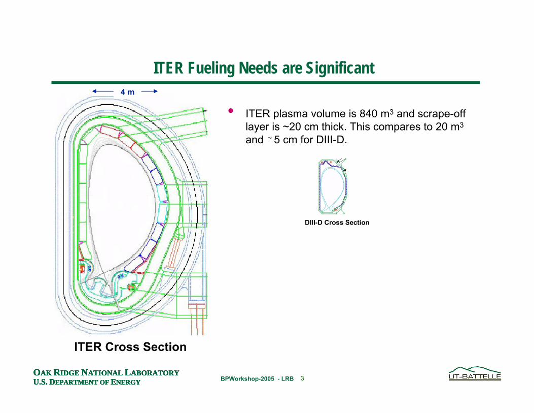
• ITER plasma volume is 840 m3 and scrape-off layer is ~20 cm thick. This compares to 20 m3
and ~ 5 cm for DIII-D.
ITER Fueling Needs are Significant
ITER Cross Section
4 m
DIII-D Cross Section

8OAK RIDGE NATIONAL LABORATORYU.S. DEPARTMENT OF ENERGYOAK RIDGE NATIONAL LABORATORYU.S. DEPARTMENT OF ENERGYOAK RIDGE NATIONAL LABORATORYU.S. DEPARTMENT OF ENERGY BPWorkshop-2005 - LRBOAK RIDGE NATIONAL LABORATORYU.S. DEPARTMENT OF ENERGY
• ITER plasma volume is 840 m3 and scrape-off layer is ~30 cm thick. This compares to 20 m3
and ~ 5 cm for DIII-D.
• ITER is designed to operate at high density (> 1x 10²⁰ m-3) in order to optimize Q.
• Gas to be introduce from 4 ports on outside and 3 in the divertor region
• NBI fueling to be negligible (< 2 x 10²⁰ atoms/s or < 3 torr-L/s )
• Inside wall pellet injection planned for deep fueling and high efficiency. Reliability must be very high.
• Pellet injector must operate for up to 1 hour continuously and produce up to 4500 cm3 of DT ice per discharge.
ITER Fueling Needs are Significant
ITER Cross Section
GasInjectorsPellet
Injection
4 m
9OAK RIDGE NATIONAL LABORATORYU.S. DEPARTMENT OF ENERGYOAK RIDGE NATIONAL LABORATORYU.S. DEPARTMENT OF ENERGYOAK RIDGE NATIONAL LABORATORYU.S. DEPARTMENT OF ENERGY BPWorkshop-2005 - LRBOAK RIDGE NATIONAL LABORATORYU.S. DEPARTMENT OF ENERGY
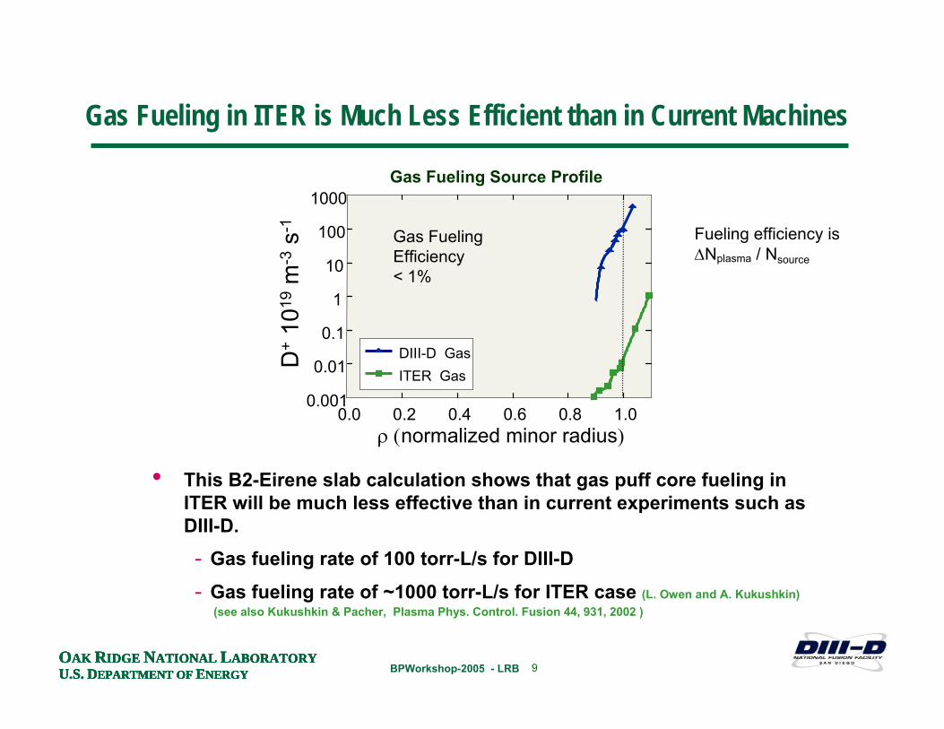
Gas Fueling in ITER is Much Less Efficient than in Current Machines
D+
1019
m-3
s-1
• This B2-Eirene slab calculation shows that gas puff core fueling in ITER will be much less effective than in current experiments such as DIII-D.- Gas fueling rate of 100 torr-L/s for DIII-D
- Gas fueling rate of ~1000 torr-L/s for ITER case (L. Owen and A. Kukushkin)(see also Kukushkin & Pacher, Plasma Phys. Control. Fusion 44, 931, 2002 )
0.0 0.2 0.4 0.6 0.8 1.00.001
0.01
0.1
1
10
100
1000
DIII-D GasITER Gas
ρ (normalized minor radius)
Gas Fueling Efficiency < 1%
Gas Fueling Source Profile
Fueling efficiency is ∆Nplasma / Nsource
10OAK RIDGE NATIONAL LABORATORYU.S. DEPARTMENT OF ENERGYOAK RIDGE NATIONAL LABORATORYU.S. DEPARTMENT OF ENERGYOAK RIDGE NATIONAL LABORATORYU.S. DEPARTMENT OF ENERGY BPWorkshop-2005 - LRBOAK RIDGE NATIONAL LABORATORYU.S. DEPARTMENT OF ENERGY
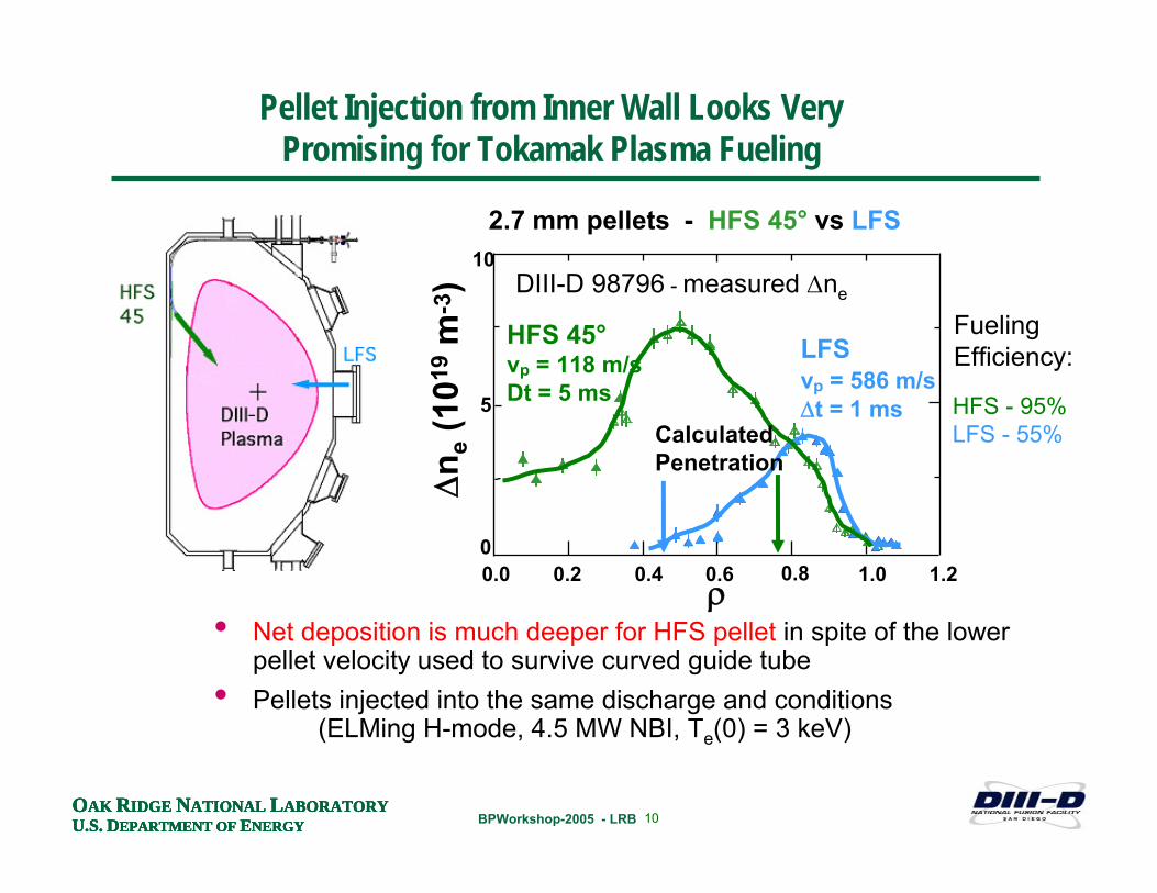
Pellet Injection from Inner Wall Looks Very Promising for Tokamak Plasma Fueling
• Net deposition is much deeper for HFS pellet in spite of the lower pellet velocity used to survive curved guide tube
• Pellets injected into the same discharge and conditions (ELMing H-mode, 4.5 MW NBI, Te(0) = 3 keV)
2.7 mm pellets - HFS 45° vs LFS
HFS 45°vp = 118 m/sDt = 5 ms
0
5
10
0.0 0.2 0.4 0.6 0.8 1.0 1.2ρ
LFSvp = 586 m/s∆t = 1 ms
∆n e
(101
9m
-3) DIII-D 98796 - measured ∆ne
Calculated Penetration
HFS - 95%LFS - 55%
FuelingEfficiency:
11OAK RIDGE NATIONAL LABORATORYU.S. DEPARTMENT OF ENERGYOAK RIDGE NATIONAL LABORATORYU.S. DEPARTMENT OF ENERGYOAK RIDGE NATIONAL LABORATORYU.S. DEPARTMENT OF ENERGY BPWorkshop-2005 - LRBOAK RIDGE NATIONAL LABORATORYU.S. DEPARTMENT OF ENERGY
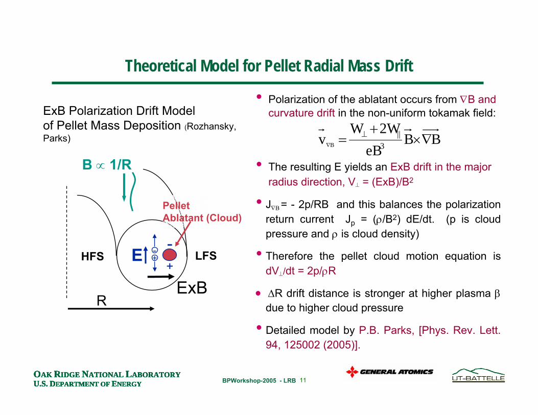
ExB Polarization Drift Modelof Pellet Mass Deposition (Rozhansky, Parks)
• J∇Β = - 2p/RB and this balances the polarization return current Jp = (ρ/B2) dE/dt. (p is cloud pressure and ρ is cloud density)
• Therefore the pellet cloud motion equation is dV⊥/dt = 2p/ρR
• ∆R drift distance is stronger at higher plasma βdue to higher cloud pressure
• Detailed model by P.B. Parks, [Phys. Rev. Lett. 94, 125002 (2005)].
-+
+
-
B ∝ 1/R
R
E
ExB
PelletAblatant (Cloud)
HFS LFS
• Polarization of the ablatant occurs from ∇B and curvature drift in the non-uniform tokamak field:
• The resulting E yields an ExB drift in the major radius direction, V⊥ = (ExB)/B2
Theoretical Model for Pellet Radial Mass Drift
BBeB
2WWv 3
||B ∇×
+= ⊥
∇
12OAK RIDGE NATIONAL LABORATORYU.S. DEPARTMENT OF ENERGYOAK RIDGE NATIONAL LABORATORYU.S. DEPARTMENT OF ENERGYOAK RIDGE NATIONAL LABORATORYU.S. DEPARTMENT OF ENERGY BPWorkshop-2005 - LRBOAK RIDGE NATIONAL LABORATORYU.S. DEPARTMENT OF ENERGY
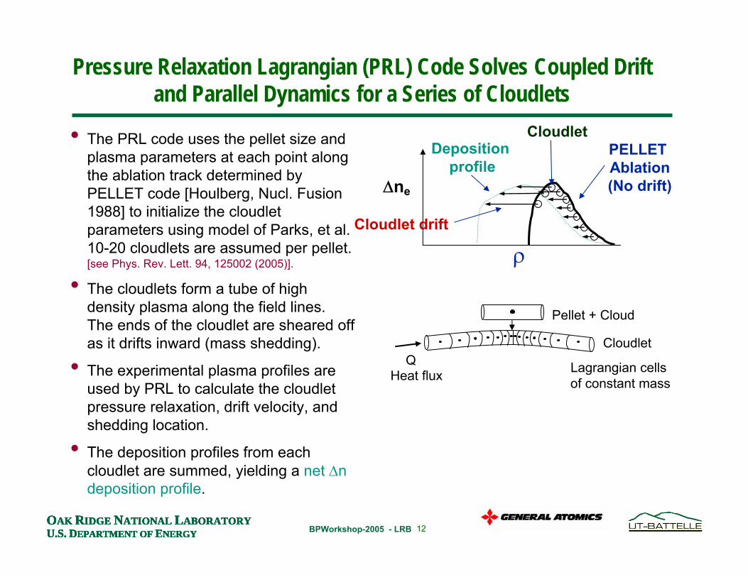
Pressure Relaxation Lagrangian (PRL) Code Solves Coupled Drift and Parallel Dynamics for a Series of Cloudlets
• The PRL code uses the pellet size and plasma parameters at each point along the ablation track determined by PELLET code [Houlberg, Nucl. Fusion 1988] to initialize the cloudlet parameters using model of Parks, et al. 10-20 cloudlets are assumed per pellet. [see Phys. Rev. Lett. 94, 125002 (2005)].
• The cloudlets form a tube of high density plasma along the field lines. The ends of the cloudlet are sheared off as it drifts inward (mass shedding).
• The experimental plasma profiles are used by PRL to calculate the cloudlet pressure relaxation, drift velocity, and shedding location.
• The deposition profiles from each cloudlet are summed, yielding a net ∆ndeposition profile.
PELLET Ablation(No drift)
Cloudlet
∆ne
Deposition profile
Cloudlet drift
ρ
Cloudlet
Lagrangian cells of constant mass
QHeat flux
Pellet + Cloud
13OAK RIDGE NATIONAL LABORATORYU.S. DEPARTMENT OF ENERGYOAK RIDGE NATIONAL LABORATORYU.S. DEPARTMENT OF ENERGYOAK RIDGE NATIONAL LABORATORYU.S. DEPARTMENT OF ENERGY BPWorkshop-2005 - LRBOAK RIDGE NATIONAL LABORATORYU.S. DEPARTMENT OF ENERGY
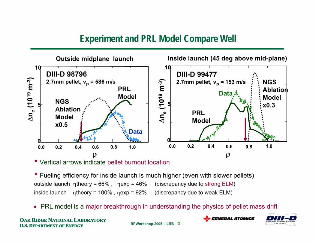
Experiment and PRL Model Compare Well
0
5
10
0.0 0.2 0.4 0.6 0.8 1.0ρ
∆n e
(101
9m
-3) DIII-D 98796
2.7mm pellet, vp = 586 m/sPRL Model
0
5
10
0.0 0.2 0.4 0.6 0.8 1.0
ρ∆
n e(1
019
m-3
) DIII-D 994772.7mm pellet, vp = 153 m/s
Data
Outside midplane launch Inside launch (45 deg above mid-plane)
Data
• Vertical arrows indicate pellet burnout location
• Fueling efficiency for inside launch is much higher (even with slower pellets)outside launch ηtheory = 66% , ηexp = 46% (discrepancy due to strong ELM)inside launch ηtheory = 100% , ηexp = 92% (discrepancy due to weak ELM)
• PRL model is a major breakthrough in understanding the physics of pellet mass drift
PRL Model
NGS AblationModelx0.3NGS
AblationModelx0.5
14OAK RIDGE NATIONAL LABORATORYU.S. DEPARTMENT OF ENERGYOAK RIDGE NATIONAL LABORATORYU.S. DEPARTMENT OF ENERGYOAK RIDGE NATIONAL LABORATORYU.S. DEPARTMENT OF ENERGY BPWorkshop-2005 - LRBOAK RIDGE NATIONAL LABORATORYU.S. DEPARTMENT OF ENERGY
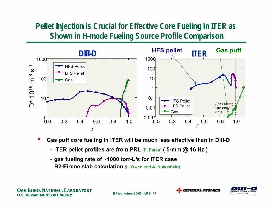
D+
1019
m-3
s-1
DIII-D
• Gas puff core fueling in ITER will be much less effective than in DIII-D- ITER pellet profiles are from PRL (P. Parks) ( 5-mm @ 16 Hz )
- gas fueling rate of ~1000 torr-L/s for ITER case B2-Eirene slab calculation (L. Owen and A. Kukushkin)
ρ0.0 0.2 0.4 0.6 0.8 1.0
1
10
100
1000HFS PelletLFS PelletGas
0.0 0.2 0.4 0.6 0.8 1.00.001
0.01
0.1
1
10
100
1000
HFS PelletLFS PelletGas
ρ
ITER
Gas Fueling Efficiency < 1%
HFS pellet Gas puff
Pellet Injection is Crucial for Effective Core Fueling in ITER as Shown in H-mode Fueling Source Profile Comparison
15OAK RIDGE NATIONAL LABORATORYU.S. DEPARTMENT OF ENERGYOAK RIDGE NATIONAL LABORATORYU.S. DEPARTMENT OF ENERGYOAK RIDGE NATIONAL LABORATORYU.S. DEPARTMENT OF ENERGY BPWorkshop-2005 - LRBOAK RIDGE NATIONAL LABORATORYU.S. DEPARTMENT OF ENERGY
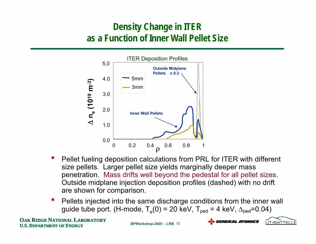
Density Change in ITERas a Function of Inner Wall Pellet Size
• Pellet fueling deposition calculations from PRL for ITER with different size pellets. Larger pellet size yields marginally deeper mass penetration. Mass drifts well beyond the pedestal for all pellet sizes. Outside midplane injection deposition profiles (dashed) with no drift are shown for comparison.
• Pellets injected into the same discharge conditions from the inner wall guide tube port. (H-mode, Te(0) = 20 keV, Tped = 4 keV, ∆ped=0.04)
0.0
1.0
2.0
3.0
4.0
5.0
0 0.2 0.4 0.6 0.8 1
5mm
∆n e
(101
9m
-3)
3mm
ρ
ITER Deposition ProfilesOutside MidplanePellets x 0.3
Inner Wall Pellets
16OAK RIDGE NATIONAL LABORATORYU.S. DEPARTMENT OF ENERGYOAK RIDGE NATIONAL LABORATORYU.S. DEPARTMENT OF ENERGYOAK RIDGE NATIONAL LABORATORYU.S. DEPARTMENT OF ENERGY BPWorkshop-2005 - LRBOAK RIDGE NATIONAL LABORATORYU.S. DEPARTMENT OF ENERGY
0
2
4
6
8
0 0.2 0.4 0.6 0.8 1ρ
∆n e
(101
9 m-3
) k=2k=5k=20
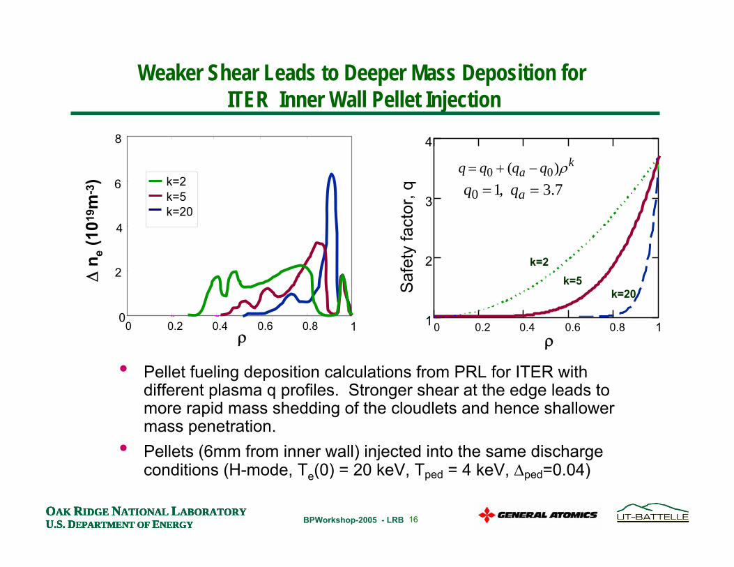
Weaker Shear Leads to Deeper Mass Deposition for ITER Inner Wall Pellet Injection
0 0.2 0.4 0.6 0.81
2
3
4
ρ
Saf
ety
fact
or, q
• Pellet fueling deposition calculations from PRL for ITER with different plasma q profiles. Stronger shear at the edge leads to more rapid mass shedding of the cloudlets and hence shallower mass penetration.
• Pellets (6mm from inner wall) injected into the same discharge conditions (H-mode, Te(0) = 20 keV, Tped = 4 keV, ∆ped=0.04)
1
k=2
q = q0 + (qa − q0)ρk
k=5k=20
q0 =1, qa = 3.7

17OAK RIDGE NATIONAL LABORATORYU.S. DEPARTMENT OF ENERGYOAK RIDGE NATIONAL LABORATORYU.S. DEPARTMENT OF ENERGYOAK RIDGE NATIONAL LABORATORYU.S. DEPARTMENT OF ENERGY BPWorkshop-2005 - LRBOAK RIDGE NATIONAL LABORATORYU.S. DEPARTMENT OF ENERGY
• ITER will initially have 2 pellet injectors that each provide D2, DT, T2 pellets (5mm @ 16Hz, 3mm @ 32Hz).
• Inside wall pellet injection for deep fueling beyond the pedestal and high efficiency. Reliability must be very high.
• Guide tubes bring the pellets in from divertor ports and routes them to the inner wall.
• Pellet injector must operate for up to 1 hour continuously and produce ~ 1.5 cm3/s of ice.
ITER Pellet Fueling Requirements
Pellet Path in ITER
18OAK RIDGE NATIONAL LABORATORYU.S. DEPARTMENT OF ENERGYOAK RIDGE NATIONAL LABORATORYU.S. DEPARTMENT OF ENERGYOAK RIDGE NATIONAL LABORATORYU.S. DEPARTMENT OF ENERGY BPWorkshop-2005 - LRBOAK RIDGE NATIONAL LABORATORYU.S. DEPARTMENT OF ENERGY
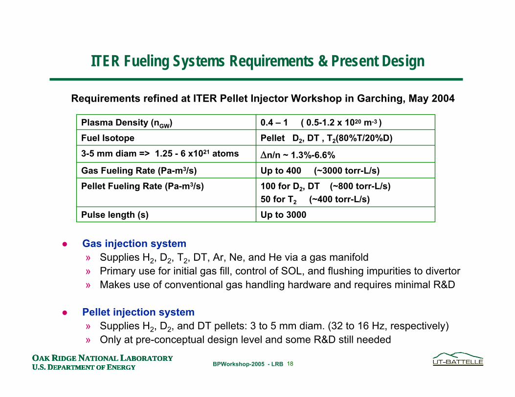
Up to 3000 Pulse length (s)
100 for D2, DT (~800 torr-L/s)50 for T2 (~400 torr-L/s)
Pellet Fueling Rate (Pa-m3/s)Up to 400 (~3000 torr-L/s)Gas Fueling Rate (Pa-m3/s)∆n/n ~ 1.3%-6.6%3-5 mm diam => 1.25 - 6 x10²¹ atomsPellet D2, DT , T2(80%T/20%D)Fuel Isotope0.4 – 1 ( 0.5-1.2 x 10²⁰ m-3 )Plasma Density (nGW)
Gas injection system» Supplies H2, D2, T2, DT, Ar, Ne, and He via a gas manifold» Primary use for initial gas fill, control of SOL, and flushing impurities to divertor» Makes use of conventional gas handling hardware and requires minimal R&D
Pellet injection system» Supplies H2, D2, and DT pellets: 3 to 5 mm diam. (32 to 16 Hz, respectively)» Only at pre-conceptual design level and some R&D still needed
Requirements refined at ITER Pellet Injector Workshop in Garching, May 2004
ITER Fueling Systems Requirements & Present Design
19OAK RIDGE NATIONAL LABORATORYU.S. DEPARTMENT OF ENERGYOAK RIDGE NATIONAL LABORATORYU.S. DEPARTMENT OF ENERGYOAK RIDGE NATIONAL LABORATORYU.S. DEPARTMENT OF ENERGY BPWorkshop-2005 - LRBOAK RIDGE NATIONAL LABORATORYU.S. DEPARTMENT OF ENERGY
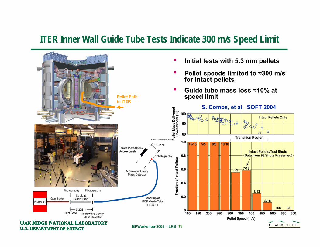
• Initial tests with 5.3 mm pellets
• Pellet speeds limited to ≈300 m/sfor intact pellets
• Guide tube mass loss ≈10% at speed limit
ITER Inner Wall Guide Tube Tests Indicate 300 m/s Speed Limit
S. Combs, et al. SOFT 2004
Pellet Path in ITER
20OAK RIDGE NATIONAL LABORATORYU.S. DEPARTMENT OF ENERGYOAK RIDGE NATIONAL LABORATORYU.S. DEPARTMENT OF ENERGYOAK RIDGE NATIONAL LABORATORYU.S. DEPARTMENT OF ENERGY BPWorkshop-2005 - LRBOAK RIDGE NATIONAL LABORATORYU.S. DEPARTMENT OF ENERGY
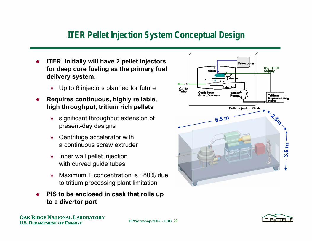
ITER initially will have 2 pellet injectors for deep core fueling as the primary fuel delivery system.
» Up to 6 injectors planned for future
Requires continuous, highly reliable, high throughput, tritium rich pellets
» significant throughput extension of present-day designs
» Centrifuge accelerator witha continuous screw extruder
» Inner wall pellet injection with curved guide tubes
» Maximum T concentration is ~80% due to tritium processing plant limitation
PIS to be enclosed in cask that rolls up to a divertor port
6.5 m 2.5m
3.6
m
ITER Pellet Injection System Conceptual Design
Rotor Arm
Extruder
D2, T2, DTSupply
Vacuum Pump Tritium
Reprocessing Plant
GuideTube Centrifuge
Guard Vacuum
Pellet Injection Cask
Cryocooler
Cutter
Rotor Arm
Extruder
D2, T2, DTSupply
Vacuum Pump Tritium
Reprocessing Plant
GuideTube Centrifuge
Guard Vacuum
Pellet Injection Cask
Cryocooler
Cutter
21OAK RIDGE NATIONAL LABORATORYU.S. DEPARTMENT OF ENERGYOAK RIDGE NATIONAL LABORATORYU.S. DEPARTMENT OF ENERGYOAK RIDGE NATIONAL LABORATORYU.S. DEPARTMENT OF ENERGY BPWorkshop-2005 - LRBOAK RIDGE NATIONAL LABORATORYU.S. DEPARTMENT OF ENERGY
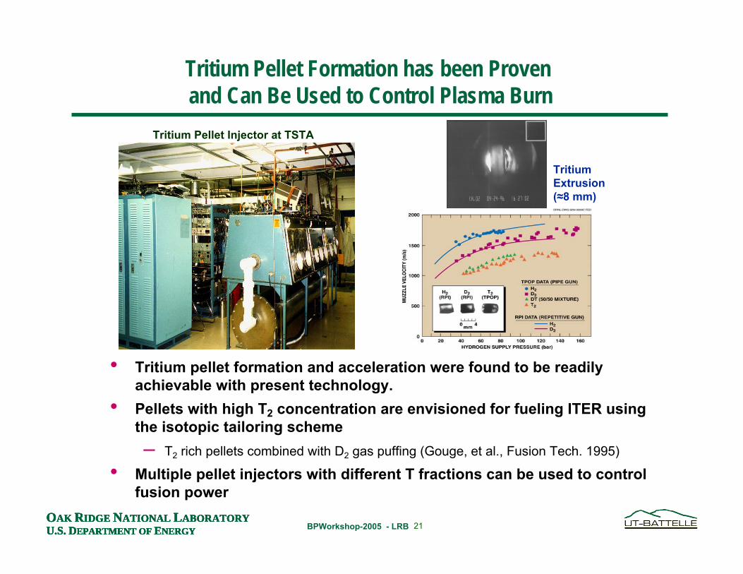
• Tritium pellet formation and acceleration were found to be readily achievable with present technology.
• Pellets with high T2 concentration are envisioned for fueling ITER using the isotopic tailoring scheme – T2 rich pellets combined with D2 gas puffing (Gouge, et al., Fusion Tech. 1995)
• Multiple pellet injectors with different T fractions can be used to control fusion power
Tritium Pellet Injector at TSTA
Tritium Extrusion(≈8 mm)
Tritium Pellet Formation has been Proven and Can Be Used to Control Plasma Burn
22OAK RIDGE NATIONAL LABORATORYU.S. DEPARTMENT OF ENERGYOAK RIDGE NATIONAL LABORATORYU.S. DEPARTMENT OF ENERGYOAK RIDGE NATIONAL LABORATORYU.S. DEPARTMENT OF ENERGY BPWorkshop-2005 - LRBOAK RIDGE NATIONAL LABORATORYU.S. DEPARTMENT OF ENERGY
D2
He
LHe
ScrewHeatExchangerSolid D2
VacuumPump
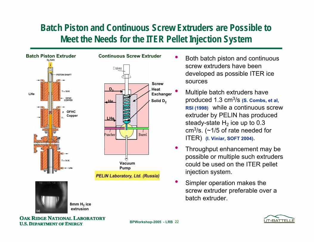
Batch Piston and Continuous Screw Extruders are Possible to Meet the Needs for the ITER Pellet Injection System
• Both batch piston and continuous screw extruders have been developed as possible ITER ice sources
• Multiple batch extruders have produced 1.3 cm3/s (S. Combs, et al, RSI (1998) while a continuous screw extruder by PELIN has produced steady-state H2 ice up to 0.3 cm3/s. (~1/5 of rate needed for ITER) (I. Viniar, SOFT 2004).
• Throughput enhancement may be possible or multiple such extruders could be used on the ITER pellet injection system.
• Simpler operation makes the screw extruder preferable over a batch extruder.
LHe
OFHC Copper
Batch Piston Extruder Continuous Screw Extruder
8mm H2 iceextrusion
23OAK RIDGE NATIONAL LABORATORYU.S. DEPARTMENT OF ENERGYOAK RIDGE NATIONAL LABORATORYU.S. DEPARTMENT OF ENERGYOAK RIDGE NATIONAL LABORATORYU.S. DEPARTMENT OF ENERGY BPWorkshop-2005 - LRBOAK RIDGE NATIONAL LABORATORYU.S. DEPARTMENT OF ENERGY
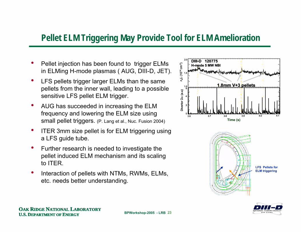
Pellet ELM Triggering May Provide Tool for ELM Amelioration
• Pellet injection has been found to trigger ELMsin ELMing H-mode plasmas ( AUG, DIII-D, JET).
• LFS pellets trigger larger ELMs than the same pellets from the inner wall, leading to a possible sensitive LFS pellet ELM trigger.
• AUG has succeeded in increasing the ELM frequency and lowering the ELM size using small pellet triggers. (P. Lang et al., Nuc. Fusion 2004)
• ITER 3mm size pellet is for ELM triggering using a LFS guide tube.
• Further research is needed to investigate the pellet induced ELM mechanism and its scaling to ITER.
• Interaction of pellets with NTMs, RWMs, ELMs, etc. needs better understanding.
DIII-D 120775H-mode 5 MW NBI
0
2
4
61.0
1.5
2.0
Div
erto
r Dα
(a.u
)n e
L(1
014 c
m-2
)
3.6 3.7 3.8 3.9 4.0 4.1
1.8mm V+3 pellets
DIII-D 120775H-mode 5 MW NBI
0
2
4
61.0
1.5
2.0
Div
erto
r Dα
(a.u
)n e
L(1
014 c
m-2
)
3.6 3.7 3.8 3.9 4.0 4.1
1.8mm V+3 pellets
Time (s)
LFS Pellets forELM triggering
24OAK RIDGE NATIONAL LABORATORYU.S. DEPARTMENT OF ENERGYOAK RIDGE NATIONAL LABORATORYU.S. DEPARTMENT OF ENERGYOAK RIDGE NATIONAL LABORATORYU.S. DEPARTMENT OF ENERGY BPWorkshop-2005 - LRBOAK RIDGE NATIONAL LABORATORYU.S. DEPARTMENT OF ENERGY
• ITER will require significant fueling beyond that provided by gas
» Gas fueling and recycling expected to be very inefficient
• Inner wall injection port will allow up to 300 m/s pellet injection
• Modeling of the proposed ITER pellet injection scenario looks promising for core fueling well beyond the H-mode pedestal
» Further validation of the ExB polarization drift model is needed with diagnostics and scalingstudies
• The pellet fueling system for ITER presents challenges for the technology developers in throughput and reliability, concepts look promising
» Development is underway and expected to take ~ 5 yrs
» Centrifuge and extruder prototypes will be produced which can be available to test on existing tokamak devices
• ELM triggering by small LFS pellets also a promising technique for ITER
» Further research to optimize and understand physics of pellet induced ELMs and ELM amelioration is required as well as other MHD interactions.
Summary


![Department of Physics · Experiment: 69:3 2:8 MeV[BABAR, PRL 2008, 2009, CLEO, PRD 2009] perturbative QCD (potential NRQCD): 39 14 MeV[Kniehl et al., PRL 2004] Perturbation theory](https://static.fdocument.org/doc/165x107/6056617afe13dc3e502be105/department-of-physics-experiment-693-28-mevbabar-prl-2008-2009-cleo-prd.jpg)