
Operation Experience and Performance Limitations in...
5
OPERATION EXPERIENCE AND PERFORMANCE LIMITATIONS IN e+e- FACTORIES K. Oide, KEK, Oho, Tsukuba, Ibaraki 305-0801, Japan Abstract Since 1999 three double-ring e+e- colliders have been operating. PEP–II and KEKB are asymmetric B–factories at Υ(4S), and DAΦNE is a Φ-factory. Generally speaking, the two B-factories have more or less common issues, and the Φ–factory has somewhat different issues from the B– factories. This paper first describes two B-factories, then discusses on DAΦN later. The description on DAΦNE owes Dr. M. Preger. 1 ASYMMETRIC B–FACTORIES 1.1 Successful Startup Figure 1 shows the development of the peak and the inte- grated luminosities of PEP–II and KEKB since 1999. This figure obviously tells the success of two machines. PEP–II reached its design luminosity, 3 /nb/s, in the fall of 2000, Figure 1: The increase of the integrated (upper) and peak (lower) luminosities of PEP–II and KEKB since 1999. only 15 months after the startup of the BaBar detector. It also exceeded its design luminosity by 50% (4.6 /nb/s) in the fall of 2001. The integrated luminosity is approach- ing 90 /fb in May 2002. KEKB started the luminosity run in 1999, and the startup speed was somewhat slower than PEP–II’s. The main obstacle at that time was the electron- cloud effects and various machine failures due to the high current operation. The peak luminosity of KEKB surpassed PEP–II’s in March 2001 and it reached 7.3 /nb/s in May 2002, which is still 30% below its design value, 10 /nb/s. Though the peak luminosity of KEKB has been higher than PEP–II’s since 2001, the integrated luminosities of two ma- chines in 2001 through 2002 were roughly equal to each other. The ratio of the average luminosity to the peak luminos- ity was about 76% and 62% for PEP–II and KEKB, respec- tively. The strong injector of SLAC benefits PEP–II pretty much to improve the luminosity efficiency. Also the to- tal running time in 2001 was longer in PEP–II by about 2 months than in KEKB. Both machines have already produced substantial output of particle physics as planned, including the discovery of CP violation in the B meson system. The quick start of the luminosities in the two machines was remarkable in the history of colliders. 1.2 Machine Parameters Table 1: Machine Parameters of Asymmetric B–Factories. PEP–II KEKB LER HER LER HER Energy 3.1 9.0 3.5 8.0 GeV Circumference 2200 3016 m Current 1.78 1.06 1.37 0.92 A Bunches 800 1224 N/bunch 10.2 6.1 7.0 4.7 10 10 Spacing 2.5 2.4 m Cross. Angle 0 22 mrad Emittance ε x 50 50 18 24 nm β ∗ x 35 50 59 61 cm β ∗ y 0.9 1.25 0.62 0.7 cm Hor. Size @IP 132 158 103 121 µm Ver. Size @IP 7.9 4.5 2.8 2.8 µm ε y /ε x 14 3.2 7.2 4.8 % Bunch Length 13 12 5.3 5.5 mm Beam-beam ξ x .062 .070 .080 .074 Beam-beam ξ y .056 .029 .048 .041 Luminosity 4.60 7.35 /nb/s Lum/24 hrs 303 395 /pb Lum/7 days 1790 2524 /pb Lum/30 days 6666 8783 /pb Proceedings of EPAC 2002, Paris, France 1
Transcript of Operation Experience and Performance Limitations in...
OPERATION EXPERIENCE AND PERFORMANCE LIMITATIONS INe+e- FACTORIES
K. Oide, KEK, Oho, Tsukuba, Ibaraki 305-0801, JapanAbstract
Since 1999 three double-ring e+e- colliders have beenoperating. PEP–II and KEKB are asymmetric B–factoriesatΥ(4S), and DAΦNE is aΦ-factory. Generally speaking,the two B-factories have more or less common issues, andthe Φ–factory has somewhat different issues from the B–factories. This paper first describes two B-factories, thendiscusses on DAΦN later. The description on DAΦNEowes Dr. M. Preger.
1 ASYMMETRIC B–FACTORIES
1.1 Successful Startup
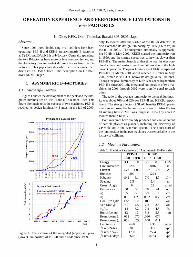
Figure 1 shows the development of the peak and the inte-grated luminosities of PEP–II and KEKB since 1999. Thisfigure obviously tells the success of two machines. PEP–IIreached its design luminosity, 3 /nb/s, in the fall of 2000,
Figure 1: The increase of the integrated (upper) and peak(lower) luminosities of PEP–II and KEKB since 1999.
only 15 months after the startup of the BaBar detector. Italso exceeded its design luminosity by 50% (4.6 /nb/s) inthe fall of 2001. The integrated luminosity is approach-ing 90 /fb in May 2002. KEKB started the luminosity runin 1999, and the startup speed was somewhat slower thanPEP–II’s. The main obstacle at that time was the electron-cloud effects and various machine failures due to the highcurrent operation. The peak luminosity of KEKB surpassedPEP–II’s in March 2001 and it reached 7.3 /nb/s in May2002, which is still 30% below its design value, 10 /nb/s.Though the peak luminosity of KEKB has been higher thanPEP–II’s since 2001, the integrated luminosities of two ma-chines in 2001 through 2002 were roughly equal to eachother.
The ratio of the average luminosity to the peak luminos-ity was about 76% and 62% for PEP–II and KEKB, respec-tively. The strong injector of SLAC benefits PEP–II prettymuch to improve the luminosity efficiency. Also the to-tal running time in 2001 was longer in PEP–II by about 2months than in KEKB.
Both machines have already produced substantial outputof particle physics as planned, including the discovery ofCP violation in the B meson system. The quick start ofthe luminosities in the two machines was remarkable in thehistory of colliders.
1.2 Machine Parameters
Table 1: Machine Parameters of Asymmetric B–Factories.PEP–II KEKB
LER HER LER HEREnergy 3.1 9.0 3.5 8.0 GeVCircumference 2200 3016 mCurrent 1.78 1.06 1.37 0.92 ABunches 800 1224N/bunch 10.2 6.1 7.0 4.7 1010
Spacing 2.5 2.4 mCross. Angle 0 22 mradEmittanceεx 50 50 18 24 nmβ∗
x 35 50 59 61 cmβ∗
y 0.9 1.25 0.62 0.7 cmHor. Size @IP 132 158 103 121 µmVer. Size @IP 7.9 4.5 2.8 2.8 µmεy/εx 14 3.2 7.2 4.8 %Bunch Length 13 12 5.3 5.5 mmBeam-beamξx .062 .070 .080 .074Beam-beamξy .056 .029 .048 .041Luminosity 4.60 7.35 /nb/s∫
Lum/24 hrs 303 395 /pb∫Lum/7 days 1790 2524 /pb∫Lum/30 days 6666 8783 /pb
Proceedings of EPAC 2002, Paris, France
1
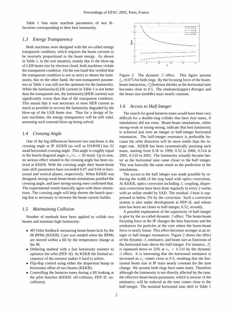
Table 1 lists main machine parameters of two B–factories corresponding to their best luminosity.
1.3 Energy Transparency
Both machines were designed with the so-called energytransparent condition, which requires the beam currents tobe inversely proportional to the beam energy. As shownin Table 1, in the real situation, mainly due to the blow-upof LER beam size by electron cloud, both machines violatethe transparent condition. On the one hand this verified thatthe transparent condition is not so strict to obtain the lumi-nosity, but on the other hand, the non-transparent parame-ters as Table 1 was still not the optimum for the luminosity.While the luminosity/(LER current) in Table 1 is not betterthan the transparent one, the luminosity/(HER current) wassignificantly worse than that of the transparent condition.This means that it was necessary to store HER current asmuch as possible to recover the luminosity degraded by theblow-up of the LER beam size. Thus for a design of fu-ture machines, the energy transparency will be still valid,assuming such external blow-up being solved.
1.4 Crossing Angle
One of the big differences between two machines is thecrossing angle at IP. KEKB (as well as DAΦNE) has 22mrad horizontal crossing angle. This angle is roughly equalto the bunch diagonal angleσx/σz = 20 mrad. Up to now,no serious effect related to the crossing angle has been no-ticed at KEKB. With the crossing angle their beam-beamtune-shift parameters have exceeded 0.07 and 0.04 in hori-zontal and vertical planes, respectively. When KEKB wasdesigned, strong-weak beam-beam simulations justified thecrossing angle, and later strong-strong ones confirmed that.The experimental results basically agree with these simula-tions. The crossing angle will help shorter the bunch spac-ing that is necessary to increase the beam current further.
1.5 Maintaining Collision
Number of methods have been applied to collide twobeams and maintain high luminosity:
• 4D Orbit feedback measuring beam-beam kick by theIR BPMs (KEKB). Care was needed when the BPMsare moved within a fill by the temperature change atthe IR.
• Dithering method with a fast luminosity monitor tooptimize the orbit (PEP–II). At KEKB the limited ac-ceptance of the monitor makes it hard to utilize.
• Flip-flop control using either the dispersion bump orhorizontal offset of two beams (KEKB).
• Controlling the betatron tunes during a fill looking atthe pilot bunches (KEKB: off-collision, PEP–II: on-collision).
Figure 2: The dynamicβ effect. This figure assumeξx=0.075 for both rings. By the focusing force of the beam-beam interaction,β∗
x(bottom) shrinks as the horizontal tunebecomes close to 0.5. The emittance(upper) diverges andthe beam size (middle) stays nearly constant.
1.6 Access to Half Integer
The search for good betatron tunes would have been verydifficult for a double-ring collider that have four tunes, ifsimulations did not exist. Beam-beam simulations, eitherstrong-weak or strong-strong, indicate that best luminosityis achieved just over an integer or half-integer horizontalresonances. The half-integer resonance is preferable be-cause the orbit distortion will be more stable than the in-teger one. KEKB has been systematically pursuing suchtunes, starting from 0.56 in 1999, 0.52 in 2000, 0.514 in2001, 0.510 in 2002. The luminosity actually became bet-ter as the horizontal tune came closer to the half integer.This was basically the same result as the prediction of thesimulations.
The access to the half integer was made possible by re-ducing the width of the stop band with optics corrections.At KEKB, optics correction includingβ, coupling, disper-sion corrections have been done regularly in every 2 weekswith an online model by SAD. The residualβ-beat is sup-pressed to below 5% by the correction. Such a correctionsystem is also under development at PEP–II, and whosetune has been set closer to half-integer, 0.52, recently.
A possible explanation of the superiority of half-integeris give by the so-called dynamicβ effect. The beam-beamfocusing force at the IP changes the beta functions and theemittances for particles at the core where the beam-beamforce is nearly linear. This effect becomes stronger at an in-teger or half-integer resonances. Figure 2 shows the effectof the dynamicβ, emittance, and beam size as functions ofthe horizontal tune above the half-integer. For instance,β∗
x
is squeezed down to 25% atνx = 0.510 by the dynamicβ effect. It is interesting that the horizontal emittance isincreased asνx comes close to 0.5, resulting that the hor-izontal beam size at IP stays nearly constant for the tunechange. We assume both rings have same tunes. Thereforealthough the luminosity is not directly affected by the tune,the effective beam-beam parameter, which is inverse of theemittance, will be reduced as the tune comes close to thehalf-integer. The nominal horizontal tune shift in Table 1
Proceedings of EPAC 2002, Paris, France
2
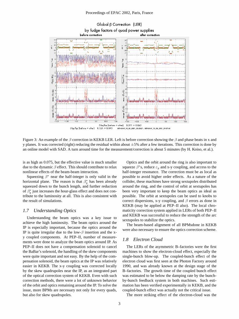
Figure 3: An example of theβ correction in KEKB LER. Left is before correction showing theβ and phase beats in x andy planes. It was corrected (right) reducing the residual within about±5% after a few iterations. This correction is done byan online model with SAD. A turn around time for the measurement/correction is about 5 minutes (by H. Koiso, et al.).
is as high as 0.075, but the effective value is much smallerdue to the dynamicβ effect. This should contribute to relaxnonlinear effects of the beam-beam interaction.
Squeezingβ∗ near the half-integer is only valid in thehorizontal plane. The reason is thatβ∗
y has been alreadysqueezed down to the bunch length, and further reductionof β∗
y just increases the hour-glass effect and does not con-tribute to the luminosity at all. This is also consistent withthe result of simulations.
1.7 Understanding Optics
Understanding the beam optics was a key issue toachieve the high luminosity. The beam optics around theIP is especially important, because the optics around theIP is quite irregular due to the low-β insertion and the x-y coupled components. At PEP–II, number of measure-ments were done to analyze the beam optics around IP. AsPEP–II does not have a compensation solenoid to cancelthe BaBar’s solenoid, the handling of the skew componentswere quite important and not easy. By the help of the com-pensation solenoid, the beam optics at the IP was relativelyeasier in KEKB. The x-y coupling was corrected locallyby the skew quadrupoles near the IP, as an integrated partof the optical correction system of KEKB. Even with suchcorrection methods, there were a lot of unknown behaviorof the orbit and optics remaining around the IP. To solve theissue, more BPMs are necessary not only for every quads,but also for skew quadrupoles.
Optics and the orbit around the ring is also important tosqueezeβ∗s, reduceεy and x-y coupling, and access to thehalf-integer resonance. The correction must be as local aspossible to avoid higher order effects. As a nature of thecollider, these machines have strong sextupoles distributedaround the ring, and the control of orbit at sextupoles hasbeen very important to keep the beam optics as ideal aspossible. The orbit at sextupoles can be used to knobs tocorrect dispersions, x-y coupling, andβ errors as done inKEKB (may be applied at PEP–II also). The local chro-maticity correction system applied in LERs of both PEP–IIand KEKB was successful to reduce the strength of the arcsextupoles to stabilize the optics.
The beam-based alignment of all BPMsdone in KEKBwere also necessary to ensure the optics correction scheme.
1.8 Electron Cloud
The LERs of the asymmetric B–factories were the firstmachines to show the electron-cloud effect, especially thesingle-bunch blow-up. The coupled-bunch effect of theelectron cloud was first seen at the Photon Factory around1990, and was already known at the design stage of theB–factories. The growth time of the coupled bunch effectwas estimated to be below the damping rate by the bunch-by-bunch feedback system in both machines. Such esti-mation has been verified experimentally in KEKB, and thecoupled-bunch effect was actually not the critical issue.
The more striking effect of the electron-cloud was the
Proceedings of EPAC 2002, Paris, France
3
single-bunch effect. It was actually predicted by F. Zim-mermann and T. Raubenheimer around 1997, well beforethe start of the B-factories, for the bunch compressor of theNLC as well as the fast-ion effect. Unfortunately it was notwell noticed by the B-factory people until the blow-up ofthe LER beam was observed in their rings. The blow-upof the vertical beam size in LER was observed in March1999 at KEKB, and was explained as a single-bunch ef-fect of the electron-cloud in October 1999 by F. Zimmer-mann. Sooner or later the blow-up was also observed atPEP–II. After that a number of measurements were doneusing synchrotron light image/interferogram, gated cam-era, gated tune meter, gated luminosity monitor, electron-cloud detector, etc. Those measurements basically supportthe prediction by the single-bunch theory and the simula-tions.
There are two sources of the electron cloud. One isthe photo-electron and the other is the multipacting withthe secondary electron at the chamber wall. The first onedominated at KEKB since the vacuum chamber is a simplecylinder, while PEP–II has an antechamber. This differ-ence was one of the factors to make the startup of KEKBslower than PEP–II until the solenoid was fully installed in2001. The major cure of the electron cloud was the externalsolenoid field both in PEP–II and KEKB. Both machineshave wound solenoids with 20 to 50 Gauss covering morethan 95% of the field-free region. As the result the electroncloud is not the critical issue at least up to the present beamcurrent with 4 bucket spacing.
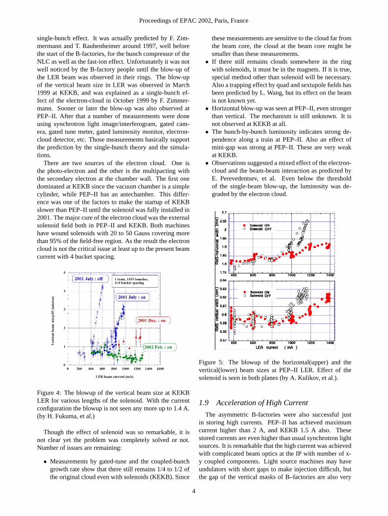
Figure 4: The blowup of the vertical beam size at KEKBLER for various lengths of the solenoid. With the currentconfiguration the blowup is not seen any more up to 1.4 A.(by H. Fukuma, et al.)
Though the effect of solenoid was so remarkable, it isnot clear yet the problem was completely solved or not.Number of issues are remaining:
• Measurements by gated-tune and the coupled-bunchgrowth rate show that there still remains 1/4 to 1/2 ofthe original cloud even with solenoids (KEKB). Since
these measurements are sensitive to the cloud far fromthe beam core, the cloud at the beam core might besmaller than these measurements.
• If there still remains clouds somewhere in the ringwith solenoids, it must be in the magnets. If it is true,special method other than solenoid will be necessary.Also a trapping effect by quad and sextupole fields hasbeen predicted by L. Wang, but its effect on the beamis not known yet.
• Horizontal blow-up was seen at PEP–II, even strongerthan vertical. The mechanism is still unknown. It isnot observed at KEKB at all.
• The bunch-by-bunch luminosity indicates strong de-pendence along a train at PEP–II. Also an effect ofmini-gap was strong at PEP–II. These are very weakat KEKB.
• Observations suggested a mixed effect of the electron-cloud and the beam-beam interaction as predicted byE. Perevedentsev, et al. Even below the thresholdof the single-beam blow-up, the luminosity was de-graded by the electron cloud.
Figure 5: The blowup of the horizontal(upper) and thevertical(lower) beam sizes at PEP–II LER. Effect of thesolenoid is seen in both planes (by A. Kulikov, et al.).
1.9 Acceleration of High Current
The asymmetric B-factories were also successful justin storing high currents. PEP–II has achieved maximumcurrent higher than 2 A, and KEKB 1.5 A also. Thesestored currents are even higher than usual synchrotron lightsources. It is remarkable that the high current was achievedwith complicated beam optics at the IP with number of x-y coupled components. Light source machines may haveundulators with short gaps to make injection difficult, butthe gap of the vertical masks of B–factories are also very
Proceedings of EPAC 2002, Paris, France
4
narrow (for instance,±3 mm for KEKB).The most difficult problem to accelerate such high cur-
rent was the stability of the beam with the rf cavities. PEP–II and KEKB took different approach at this issue. PEP–II’s rf cavity is a very compact single-mode damped cav-ity. To compensate the heavy loading of the beam, PEP–IIdeveloped a sophisticated feedback system controlling theklystron phase for each bunch together with the bunch-by-bunch longitudinal feedback. In this sense PEP–II took avery active control system. KEKB chose the opposite di-rection: passive stabilization. KEKB’s two types of cavi-ties, the ARES copper cavity and the superconducting cav-ity(SCC), both have very high stored energy to reduce thebeam loading small enough. As the result, KEKB does notneed special feedback system for the longitudinal plane.It only uses a slow 0 and -1 mode feekdbacks. Due tothe heavily damped impedances of these cavities, KEKBdoes not need bunch-by-bunch feedback for the longitudi-nal plane (it is necessary for the transverse planes to sup-press the electron-cloud, the fast-ion, and the resistive-wallinstabilities).
Though their choices were opposite, both rf schemesworked as expected up to the present stored currents. Re-maining issues are:
• The bunch-by-bunch longitudinal phase difference issignificantly higher in PEP–II.
• The availability of the SCC at KEK is limited by theregulation for the He refrigerator imposed by the gov-ernment. It is very hard to extend the running timelonger than 40 weeks per year.
1.10 Summary
• Rapid startup, good coopetition. Sufficient for theplanned physics.
• Many schemes worked as expected = victory of theaccelerator technology and the beam dynamics. Elec-tron cloud was serious, but cured by solenoid up tosome extent.
• But, no big breakthrough for future! Is Super B be-yond 100 /nb/s to be possible only by a brute force(=higher current, more power, more cost)?
2 DAΦNE
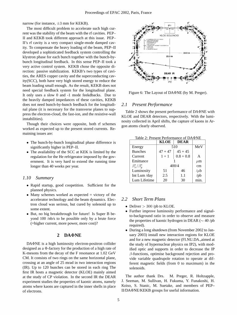
DAΦNE is a high luminosity electron-positron colliderdesigned as aΦ-factory for the production of a high rate ofK-mesons from the decay of the F resonance at 1.02 GeVCM. It consists of two rings on the same horizontal plane,crossing at an angle of 25 mrad in two interaction regions(IR). Up to 120 bunches can be stored in each ring Thefirst IR hosts a magnetic detector (KLOE) mainly aimedat the study of CP violation. In the second IR the DEARexperiment studies the properties of kaonic atoms, namelyatoms where kaons are captured in the inner shells in placeof electrons.
Figure 6: The Layout of DAΦNE (by M. Preger).
2.1 Present Performance
Table 2 shows the present performance of DAΦNE withKLOE and DEAR detectors, respectively. With the lumi-nosity collected in April shifts, the capture of kaons in Ar-gon atoms clearly observed.
Table 2: Present Performance of DAΦNEKLOE DEAR
Energy 510 MeVBunches 47 + 47 45 + 45Current 1 + 1 0.8 + 0.8 AEmittance 1 µmβ∗
x/β∗y 400/4 cm
Luminosity 51 46 /µbInt Lum /day 2.5 1.1 /pbLum Lifetime 20 30 min.
2.2 Short Term Plans
• Deliver> 300 /pb to KLOE.• Further improve luminosity performance and signal-
to-background ratio in order to observe and measurethe properties of kaonic hydrogen in DEAR (∼ 40 /pbrequired).
• During a long shutdown (from November 2002 to Jan-uary 2003) install new interaction regions for KLOEand for a new magnetic detector (FI.NU.DA.,aimed atthe study of hypernuclear physics on IP2), with mod-ified optic and supports in order to decrease the IPβ-functions, optimise background rejection and pro-vide variable quadrupole rotation to operate at dif-ferent magnetic fields (from 0 to maximum) in thesolenoids.
The author thank Drs. M. Preger, R. Holtzapple,J. Seeman, M. Sullivan, H. Fukuma, Y. Funakoshi, H.Koiso, S. Stanic, M. Suetake, and members of PEP–II/DA ΦNE/KEKB groups for useful information.
Proceedings of EPAC 2002, Paris, France
5