GEO‘s experience with Signal Recycling
29
GEO‘s experience with Signal Recycling Harald Lück Perugia, 22.9.2005
-
Upload
dara-mcfadden -
Category
Documents
-
view
27 -
download
0
description
GEO‘s experience with Signal Recycling. Harald Lück Perugia, 22.9.2005. MPR. ~600m. MSR. Dual Recycling in GEO600. Differential arm length: (gravitational wave signal) heterodyne detection S chnupp modulation. Michelson Length Control. Michelson Interferometer. 14.904875 MHz. - PowerPoint PPT Presentation
Transcript of GEO‘s experience with Signal Recycling
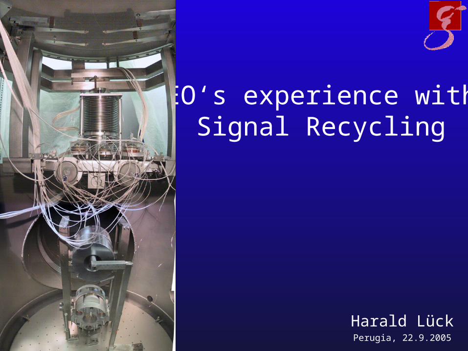
GEO‘s experience with Signal Recycling
Harald LückPerugia, 22.9.2005
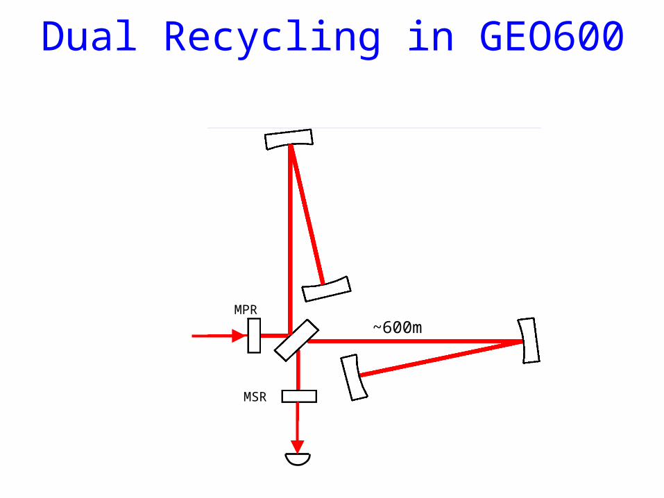
~600mMPR
MSR
Dual Recycling in GEO600
Output Mode Cleaner
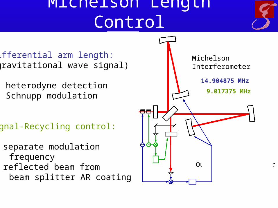
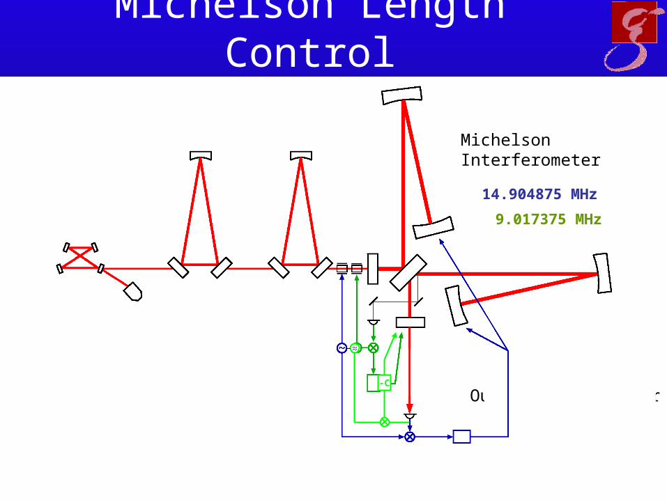
MichelsonInterferometer
14.904875 MHz
9.017375 MHz
Differential arm length:(gravitational wave signal)
heterodyne detection Schnupp modulation
Signal-Recycling control:
separate modulation frequency
reflected beam from beam splitter AR coating
Michelson Length Control
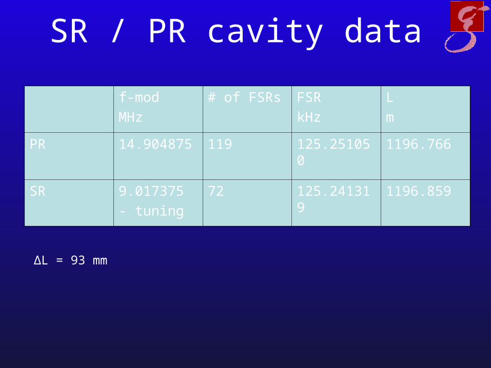
SR / PR cavity data
f-mod
MHz
# of FSRs FSR
kHz
L
m
PR 14.904875 119 125.251050 1196.766
SR 9.017375
- tuning
72 125.241319 1196.859
ΔL = 93 mm
Output Mode Cleaner
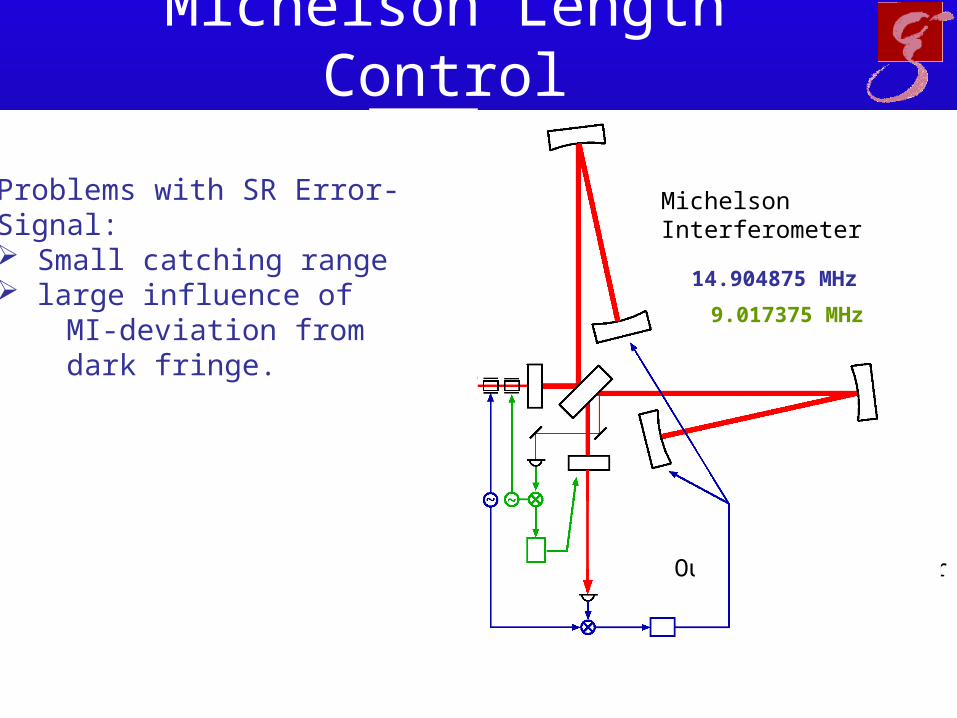
MichelsonInterferometer
14.904875 MHz
9.017375 MHz
Problems with SR Error-Signal: Small catching range large influence of MI-deviation from dark fringe.
Michelson Length Control
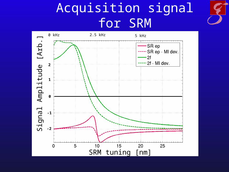
Acquisition signal for SRM
SRM tuning [nm]
Sig
nal A
mpl
itud
e [A
rb.]
2.5 kHz0 kHz 5 kHz
0
-1
-2
2
1
Output Mode Cleaner
MichelsonInterferometer
14.904875 MHz
9.017375 MHz
Michelson Length Control
~~
-C
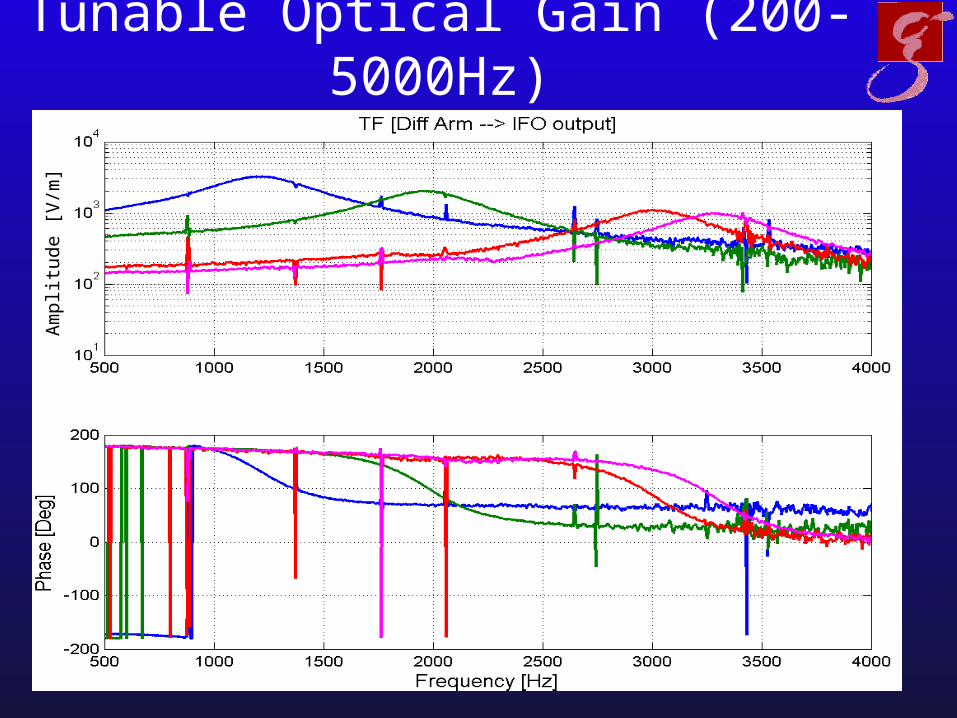
Tunable Optical Gain (200-5000Hz)A
mpl
itude
[V
/m]
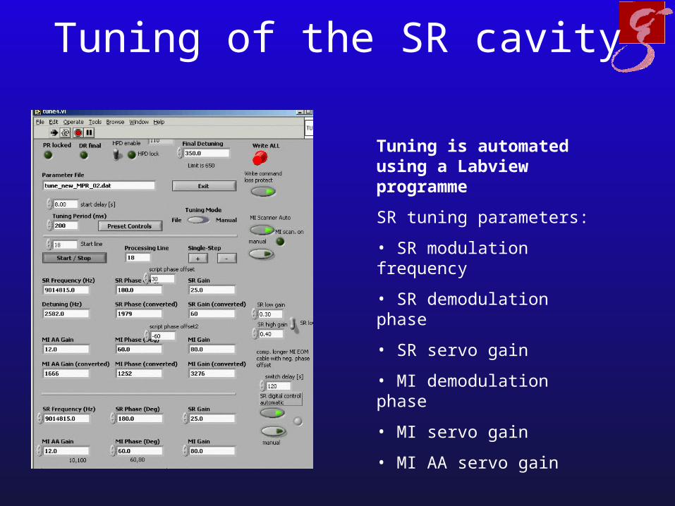
Tuning of the SR cavity
Tuning is automated using a Labview programme
SR tuning parameters:
• SR modulation frequency
• SR demodulation phase
• SR servo gain
• MI demodulation phase
• MI servo gain
• MI AA servo gain
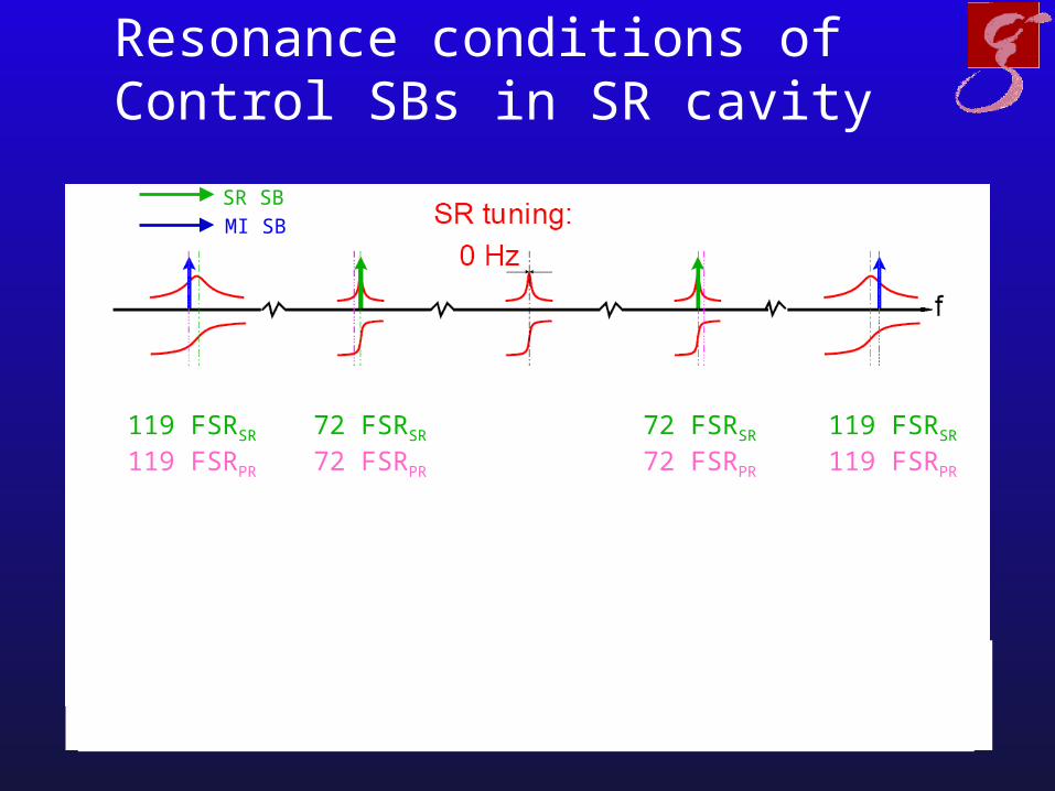
Resonance conditions of Control SBs in SR cavity
MI SB
SR SB
119 FSRSR
119 FSRPR
72 FSRSR
72 FSRPR
72 FSRSR
72 FSRPR
119 FSRSR
119 FSRPR
119 FSRSR
119 FSRPR
72 FSRSR
72 FSRPR
72 FSRSR
72 FSRPR
119 FSRSR
119 FSRPR
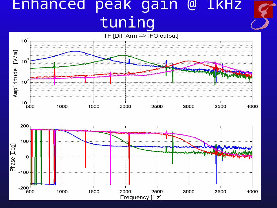
Enhanced peak gain @ 1kHz tuningA
mpl
itude
[V
/m]
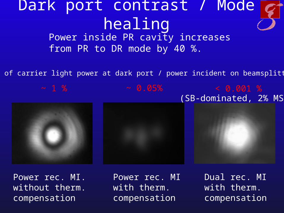
Dark port contrast / Mode healing
~ 1 % < 0.001 %
Power rec. MI.without therm.compensation
Power rec. MIwith therm.compensation
Dual rec. MIwith therm.compensation
-Ratio of carrier light power at dark port / power incident on beamsplitter
~ 0.05%(SB-dominated, 2% MSR)
Power inside PR cavity increases from PR to DR mode by 40 %.
Dual Recycled Performance
• Stable locks at desired tuning frequency with durations of up to 121h.
• Tuning frequencies 200 – 5000 Hz.
• High duty cycle in extended data taking periods ( ~97% during S4, i.e. 4 weeks)
Output Mode Cleaner
MichelsonInterferometer
14.904875 MHz
9.017375 MHz
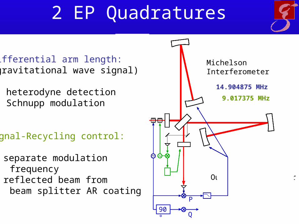
Differential arm length:(gravitational wave signal)
heterodyne detection Schnupp modulation
Signal-Recycling control:
separate modulation frequency
reflected beam from beam splitter AR coating
2 EP Quadratures
Q
P
90°
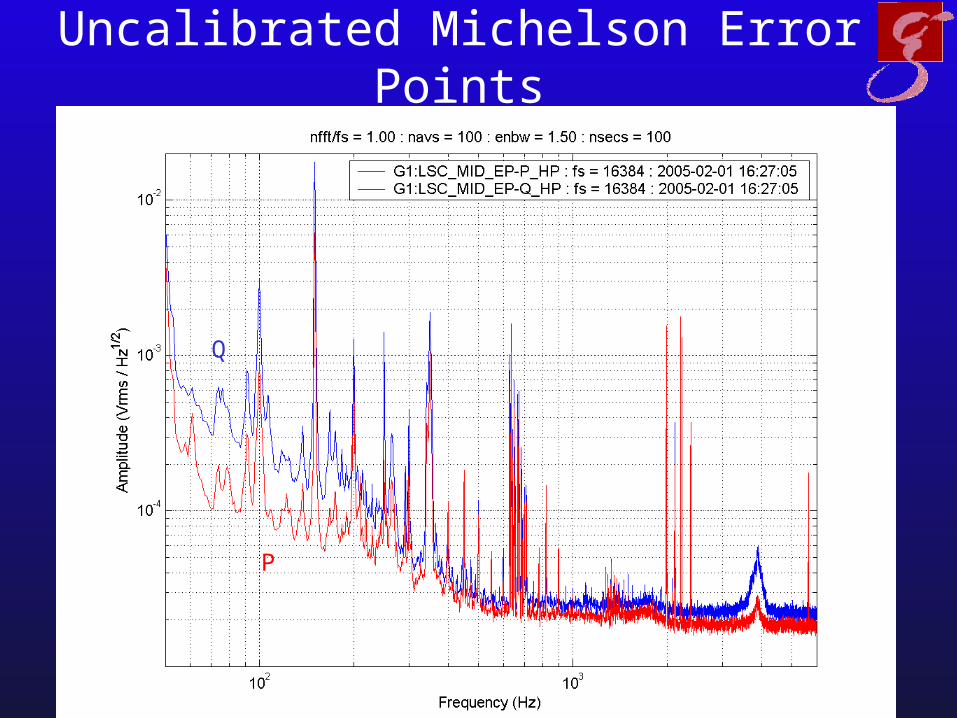
Uncalibrated Michelson Error Points
P
Q
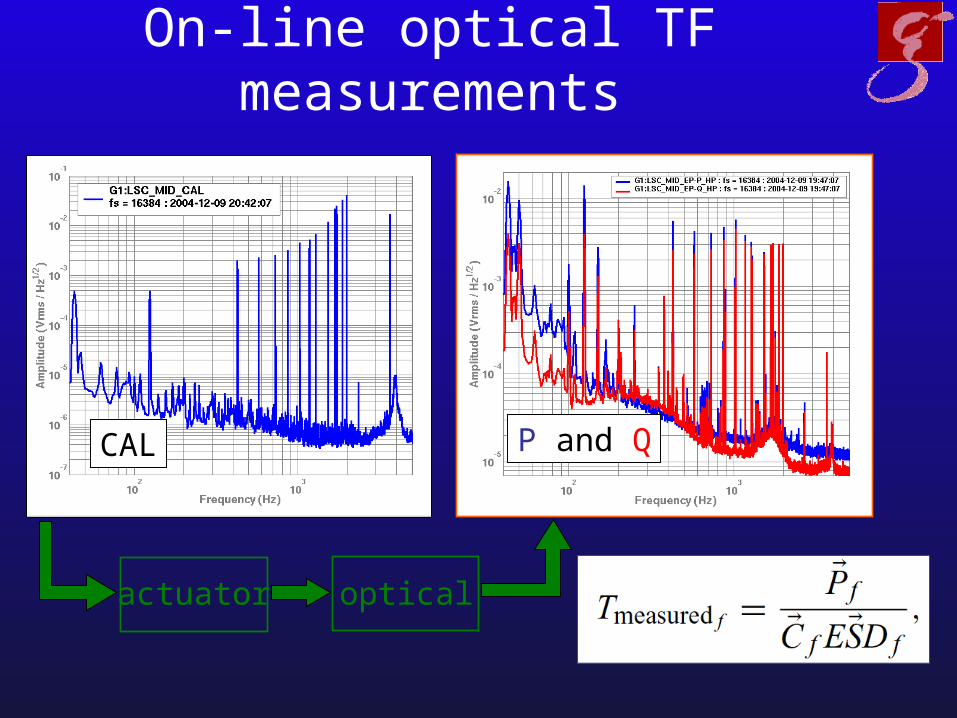
On-line optical TF measurements
actuator optical
CAL P and Q
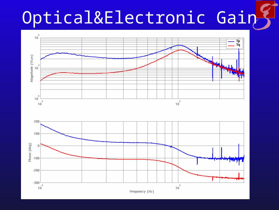
Optical&Electronic Gain

Calibration
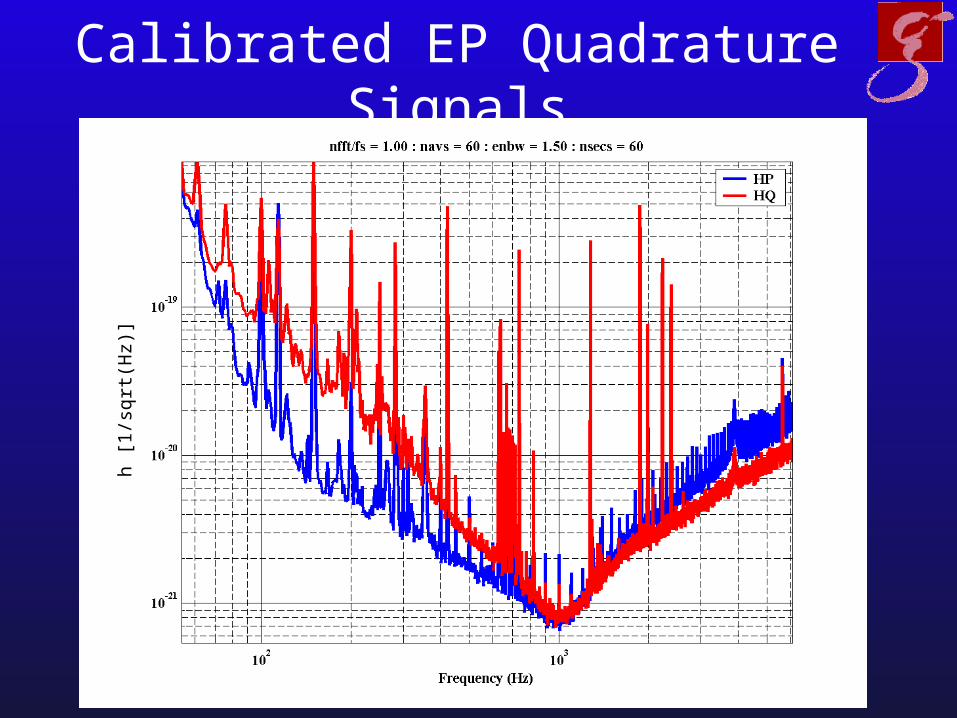
Calibrated EP Quadrature Signalsh
[1/s
qrt(
Hz)
]
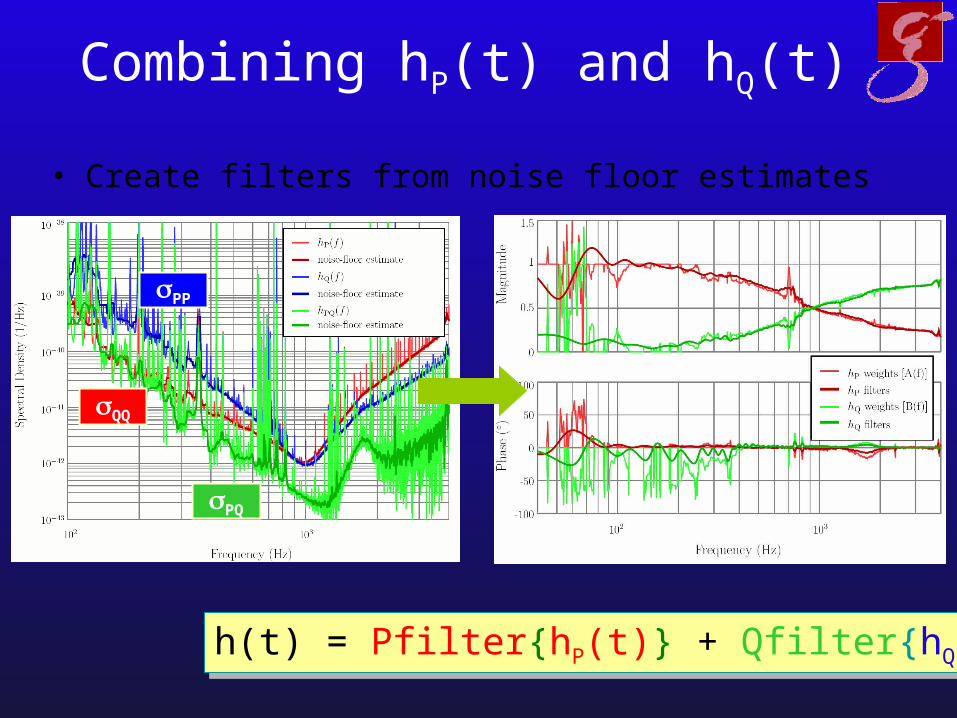
Combining hP(t) and hQ(t)
• Create filters from noise floor estimates
h(t) = Pfilter{hP(t)} + Qfilter{hQ(t)}h(t) = Pfilter{hP(t)} + Qfilter{hQ(t)}
PP
PQ
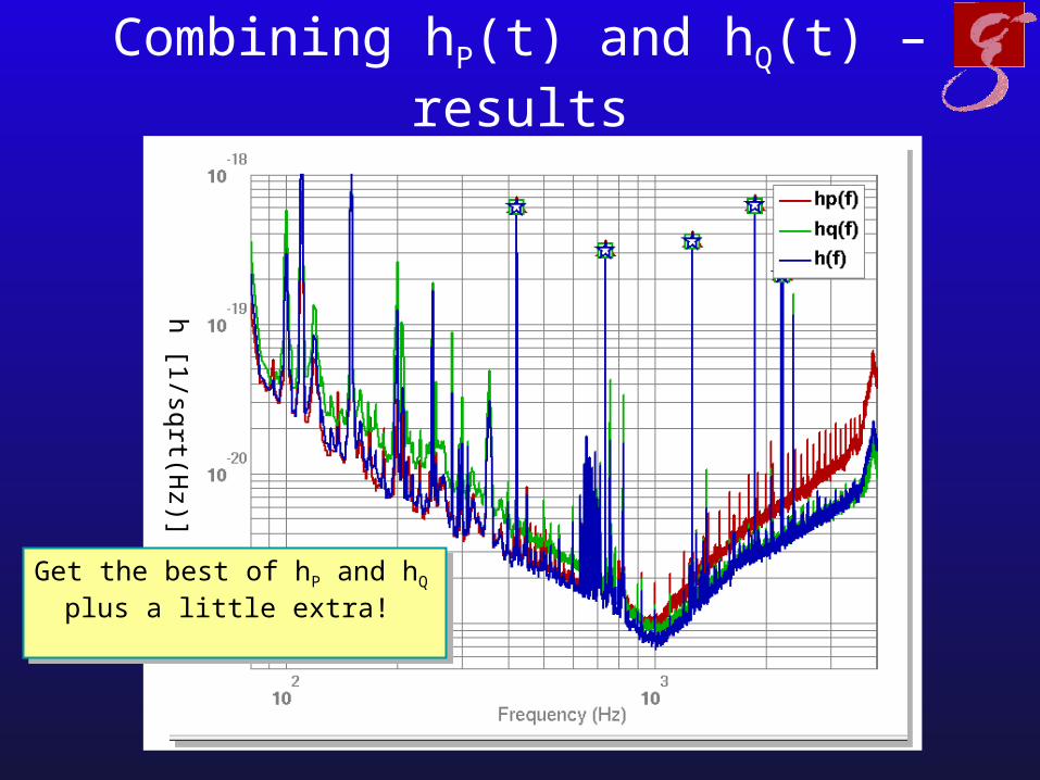
Combining hP(t) and hQ(t) – results
h [1/sqrt(Hz)]
Get the best of hP and hQ plus a little extra!
Get the best of hP and hQ plus a little extra!
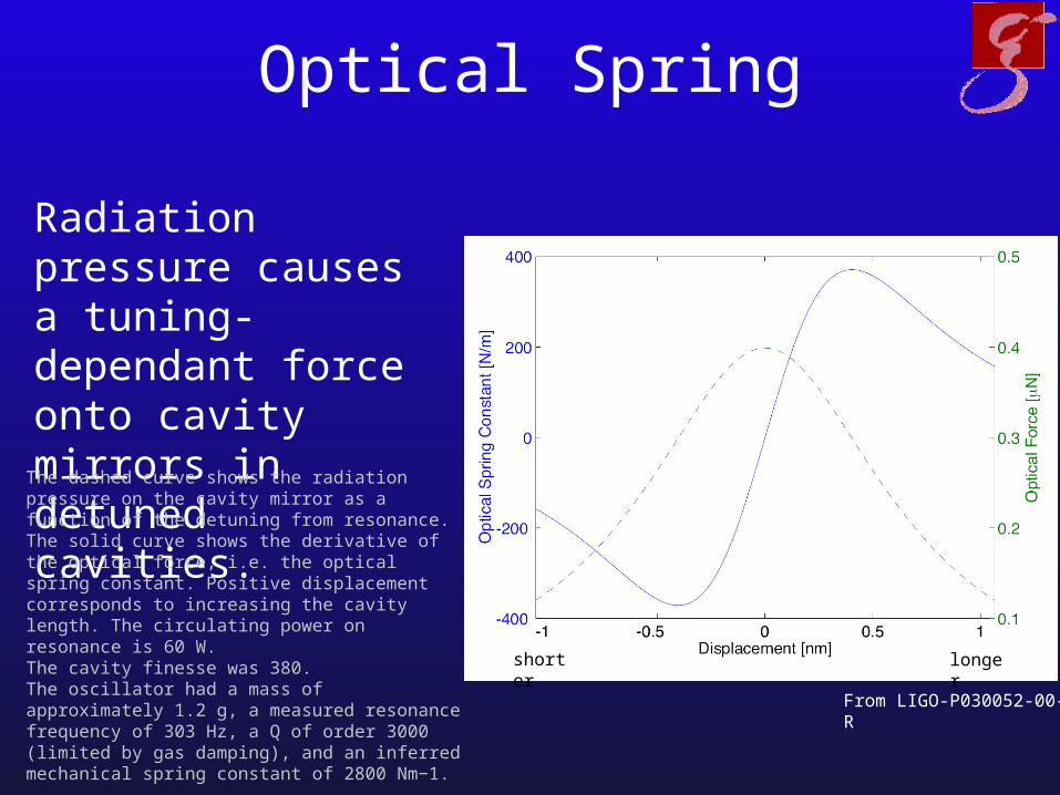
Optical Spring
Radiation pressure causes a tuning-dependant force onto cavity mirrors in detuned cavities.
From LIGO-P030052-00-R
The dashed curve shows the radiation pressure on the cavity mirror as a function of the detuning from resonance. The solid curve shows the derivative of the optical force, i.e. the optical spring constant. Positive displacement corresponds to increasing the cavity length. The circulating power on resonance is 60 W.The cavity finesse was 380. The oscillator had a mass of approximately 1.2 g, a measured resonance frequency of 303 Hz, a Q of order 3000 (limited by gas damping), and an inferred mechanical spring constant of 2800 Nm−1.
longershorter
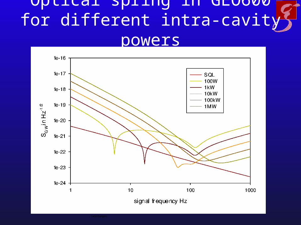
Optical spring in GEO600 for different intra-cavity powers
… Leistungen
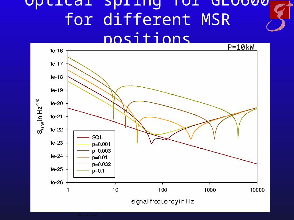
Optical spring for GEO600 for different MSR positions
… MSR Positionen
P=10kW

Summary
• tuneable response• mode healing• GW info in both quadratures• more complex SB throughput / noise TFs• optical Spring needs to be taken into account• detailed numeric simulations + understanding required for advanced detectors

?Questions?
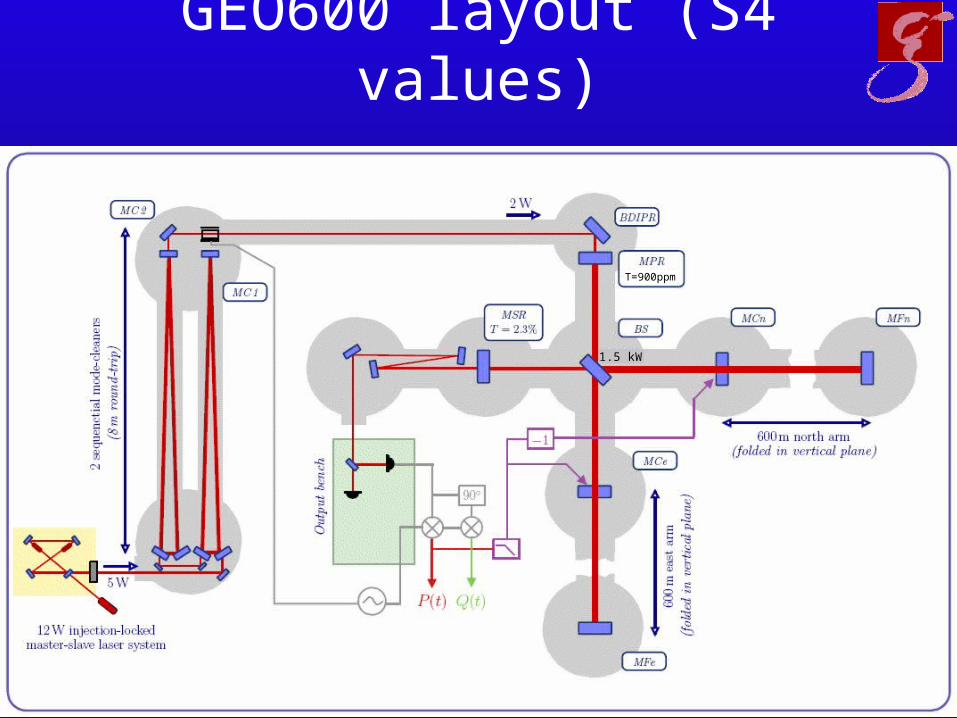
GEO600 layout (S4 values)
1.5 kW
T=900ppm
Mode healing or SB enhancement?
• Check which part of the intra cavity power enhancement comes from the control sidebands becoming resonant inside the SR cavity
• We get an enhancement of intracav power between PR and SR350Hz of 3.4/2.4 a.u.
• Sideband power inside SR? Behind MSR say 50mW -> 2W in front, so the resonant sidebands do not contribute to the power enhancement
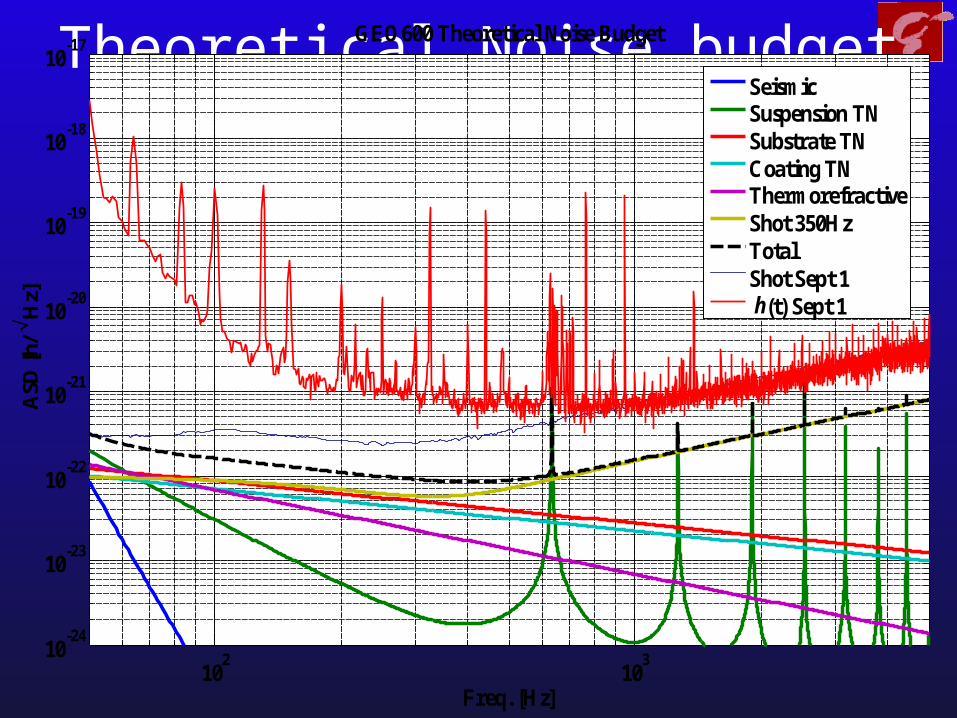
Theoretical Noise budget
102
103
10-24
10-23
10-22
10-21
10-20
10-19
10-18
10-17
Freq. [Hz]
ASD
[h/ H
z]GEO600 Theoretical Noise Budget
SeismicSuspension TNSubstrate TNCoating TNThermorefractiveShot 350HzTotalShot Sept 1 h(t) Sept 1