MODULE 2F + 3F . R 725A - genpowerusa.com DIAGRAM .....6 5 . OPERATION PRINCIPLE ... when the...
20
MODULE "2F + 3F" . R 725A MARCHE EN // AVEC LE RÉSEAU PARALLELING WITH MAINS Raccordement et réglages / Connection and adjustments Ref : 1256 - O33/d - 05.94 Alimentation Supply (U=U) C1 C2 UR UA (S1) + - [ = - ] UR UA (Cos ) Cos P1 (U=U) P2 ND MEM ON OFF (S2) (S1x S2) REGULATEUR A.V.R. Tension / Voltage (Rhe 470 Ω) SORTIE OUTPUT ϕ ϕ ϕ ∑ CALL US TODAY 1-888-POWER-58 REQUEST A QUOTE [email protected] SHOP ONLINE www.genpowerusa.com CALL US TODAY 1-888-POWER-58 REQUEST A QUOTE [email protected] SHOP ONLINE www.genpowerusa.com
Transcript of MODULE 2F + 3F . R 725A - genpowerusa.com DIAGRAM .....6 5 . OPERATION PRINCIPLE ... when the...
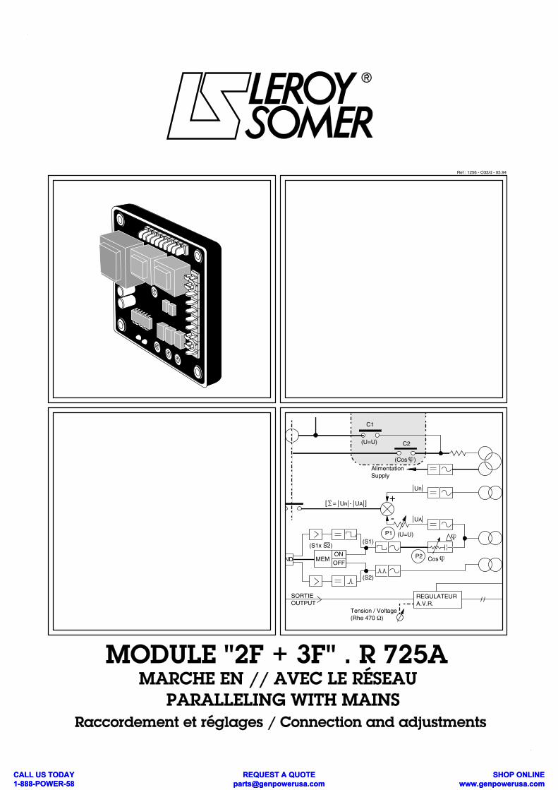
MODULE "2F + 3F" . R 725A MARCHE EN // AVEC LE RÉSEAU
PARALLELING WITH MAINSRaccordement et réglages / Connection and adjustments
Ref : 1256 - O33/d - 05.94
AlimentationSupply
(U=U)
C1
C2
UR
UA
(S1)
+
-
[ = - ] UR UA
(Cos )
Cos
P1 (U=U)
P2ND MEMON
OFF
(S2)
(S1x S2)
REGULATEURA.V.R.
Tension / Voltage(Rhe 470 Ω)
SORTIEOUTPUT
ϕ
ϕ
ϕ
∑
CALL US TODAY 1-888-POWER-58
REQUEST A QUOTE [email protected]
SHOP ONLINE www.genpowerusa.com
CALL US TODAY 1-888-POWER-58
REQUEST A QUOTE [email protected]
SHOP ONLINE www.genpowerusa.com
SOMMAIRE
1 . GENERALITES ................................................3 - 1.1 . Utilisation - 1.2 . Principe de fonctionnement
2 . ASPECT . DIMENSIONS ................................4
3 . DESCRIPTION .................................................4- 3.1 . Plage de réglage des pot. extérieurs.- 3.2 . Précautions de câblages.
4 . SCHEMA DE BRANCHEMENT .......................6
5 . FONCTIONNEMENT .......................................7
6 . REGLAGES .....................................................7- 6.1 . Plages et conditions de fonctionnement
- 6.2 . Procédure de réglage mise en route
7 . PROTECTIONS SPECIFIQUES ....................10
8 . MARCHE // AVEC AUTRE ALTERNA- TEUR (ISOLES DU RESEAU) ............................10
9 . COUPLAGE AU RESEAU EN //.....................10
10 . REGULATION DE COS Ø D'UNE INSTALLATION ............................................10
11 . DEPANNAGE .............................................12 - 11.1 . Vérification du régulateur - 11.2 . Vérification du module R 725A
12 . REGLAGES STATIQUES ...........................12
13 . REGIME DU NEUTRE.................................14
14 . TENSION HORS DES PLAGES STANDARD.................................................14
15 . ACCESSOIRES ..........................................15
16 . ASSISTANCE TECHNIQUE/PIECES DETACHEES.......................................................15
17 - SCHEMAS DE PRINCIPE ..........................16 (sens de rotation horaire) - 17 . 1. Régulateur : R 438 LS ou R 448+R 724 - 17 . 2 . Régulateur : R 129 + R 724
18 - SCHEMAS DE PRINCIPE ..........................18 (sens de rotation antihoraire) - 18 . 1. Régulateur : R 438 LS ou R 448+R 724 - 18 . 2 . Régulateur : R 129 + R 724
+ATTENTION :
1) L'ALTERNATEUR ETANT A L'ARRET, LATENSION DU RESEAU PEUT ETRE PRESENTEAUX BORNES DE DETECTION DE TENSION DUMODULE. DANGER DE MORT.
2) NE PAS EFFECTUER D'ESSAIS DIELECTRI-QUE SANS DEBRANCHER LE MODULE ET LEREGULATEUR ASSOCIE. RISQUE DE DES-TRUCTION.
INDEX
1 . GENERAL ........................................................3 - 1.1 . Purpose - 1.2 . Operating principle 2 . OUTLINE DRAWING .......................................4
3 . DESCRIPTION .................................................4- 3.1 . Adjustment range of remote pot.- 3.2 . Wiring precautions.
4 . CONNECTION DIAGRAM ...............................6
5 . OPERATION PRINCIPLE ................................7
6 . ADJUSTMENTS ..............................................7- 6.1 Operating ranges and conditions - 6.2 Adjustment procedure commissionning
7 . SPECIFIC PROTECTIONS ............................10
8 . PARALLELING WITH ANOTHER GENE- RATOR (SEPARATE FROM MAINS) ................10
9 . SYNCHRONISING WITH MAINS WHEN PARALLELING WITH OTHERS (S) GENERATORS (S) .......................................10
10 . POWER FACTOR MONITORING OF A PLANT ................................................10
11 . TROUBLE SHOOTING ................................12 - 11.1 . Checking A.V.R. - 11.2 . Checking module R 725A
12 . STATIC ADJUSTMENTS ............................12
13 . NEUTRAL POINT STATUS .........................14
14 . VOLTAGE OUT OF STANDARD RANGES.14
15 . ACCESSORIES ...........................................15
16 . TECHNICAL ASSISTANCE ........................15
17 . PRINCIPLE CONNECTION DIAGRAMS ....16 (Clockwise rotation direction) - 17 . 1 . A.V.R. : R 438 LS ou R 448 + R 724 - 17 . 2 . A.V.R. : R 129 + R 724
18 . PRINCIPLE CONNECTION DIAGRAMS ....18 (Anticlockwise direction of rotation) - 18 . 1 . A.V.R. : R 438 LS ou R 448 + R 724 - 18 . 2 . A.V.R. : R 129 + R 724
CAUTION :
1) WHEN THE GENERATOR, THE L.L. VOL-TAGE OF MAINS MAY BE ON THE VOLTAGESENSING TERMINALS OF THE MODULE. LIFE HAZARD.
2) DO NOT PROCEED TO HIGH VOLTAGETESTS WITHOUT DISCONNECTING (INSULA-TING) THE MODULE AND ASSOCIATED AVR.RISK OF DAMAGING COMPONENTS.
2
Module R 725AModule R 725A
CALL US TODAY 1-888-POWER-58
REQUEST A QUOTE [email protected]
SHOP ONLINE www.genpowerusa.com
CALL US TODAY 1-888-POWER-58
REQUEST A QUOTE [email protected]
SHOP ONLINE www.genpowerusa.com
1.GENERALITES
1.1 UtilisationLe module additionnel R 725A permet de transformer lesrégulateurs de tension suivants (la 1ère FONCTIONprincipale étant la REGULATION DE TENSION) en sys-tème de régulation dit "3 FONCTIONS" : . la 2ème FONCTION étant la régulation de COS ϕ
(facteur de puissance), en utilisant un T.I., pour fonction-ner en parallèle avec le réseau, . la 3ème FONCTION étant l'égalisation des tensionsavant couplage (U = U) qui est généralement assuréepar un synchro-coupleur asservissant le potentiomètrede réglage de tension du régulateur de tension,
REGULATEURS SYSTEMECOMPATIBLES D'EXCITATION
R 129 / R 128A compound . ACTR R 130 compound . RBC
R 438 LS AREP ou ARPI
R 448 AREP ou ARPI ou ATR
Le module doit être installé à proximité du régulateur detension (à l'intérieur ou à l'extérieur de l'alternateur).Il est relié au régulateur à la place du potentiomètre ex-térieur de réglage de tension. Le potentiomètre de réglage de tension à distance seraccorde alors (si demandé) au Module R 725A .
LES AUTRES FONCTIONS DU REGULATEUR DETENSION (PROTECTION EN SOUS-VITESSE, LIMITA-TION, SUREXCITATION...) SONT CONSERVEES.
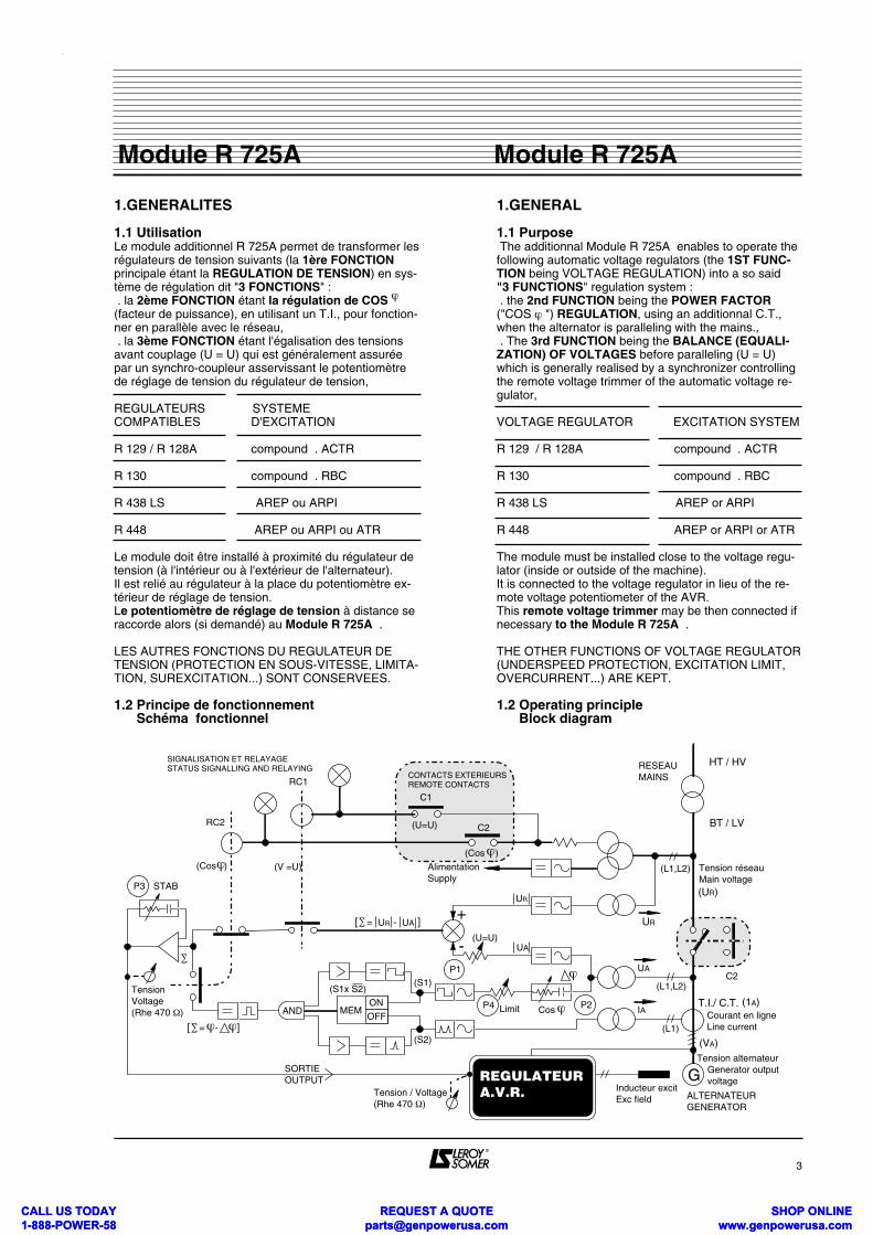
1.2 Principe de fonctionnement Schéma fonctionnel
1.GENERAL
1.1 Purpose The additionnal Module R 725A enables to operate thefollowing automatic voltage regulators (the 1ST FUNC-TION being VOLTAGE REGULATION) into a so said "3 FUNCTIONS" regulation system : . the 2nd FUNCTION being the POWER FACTOR("COS ϕ ") REGULATION, using an additionnal C.T.,when the alternator is paralleling with the mains., . The 3rd FUNCTION being the BALANCE (EQUALI-ZATION) OF VOLTAGES before paralleling (U = U)which is generally realised by a synchronizer controllingthe remote voltage trimmer of the automatic voltage re-gulator,
VOLTAGE REGULATOR EXCITATION SYSTEM
R 129 / R 128A compound . ACTR
R 130 compound . RBC R 438 LS AREP or ARPI
R 448 AREP or ARPI or ATR
The module must be installed close to the voltage regu-lator (inside or outside of the machine).It is connected to the voltage regulator in lieu of the re-mote voltage potentiometer of the AVR.This remote voltage trimmer may be then connected ifnecessary to the Module R 725A .
THE OTHER FUNCTIONS OF VOLTAGE REGULATOR(UNDERSPEED PROTECTION, EXCITATION LIMIT,OVERCURRENT...) ARE KEPT.
1.2 Operating principle Block diagram
3
Module R 725AModule R 725A
(L1,L2)
RESEAUMAINS
Tension réseauMain voltage
UR
AlimentationSupply
(U=U)
C1
C2
UR
UA
UA
(L1,L2)C2
CONTACTS EXTERIEURSREMOTE CONTACTSRC1
RC2
SIGNALISATION ET RELAYAGESTATUS SIGNALLING AND RELAYING
(S1)
+
-
[ = - ] UR UA
(Cos )(Cos )
STABP3
Cos
P1
(U=U)
P2AND
[ = - ]
MEMON
OFF
(S2)
(S1x S2)
IA
(L1)
GInducteur excitExc field
Tension / Voltage(Rhe 470 Ω)
Tension Voltage(Rhe 470 Ω)
SORTIEOUTPUT
(UR)
Courant en ligneLine current
(1A)
(VA)
T.I./ C.T.
Tension alternateur Generator output voltage
ALTERNATEURGENERATOR
(V =U)
ϕ
ϕ ϕ
ϕϕ
ϕ
∑
∑
∑
P4 Limit
HT / HV
BT / LV
REGULATEURA.V.R.
CALL US TODAY 1-888-POWER-58
REQUEST A QUOTE [email protected]
SHOP ONLINE www.genpowerusa.com
CALL US TODAY 1-888-POWER-58
REQUEST A QUOTE [email protected]
SHOP ONLINE www.genpowerusa.com
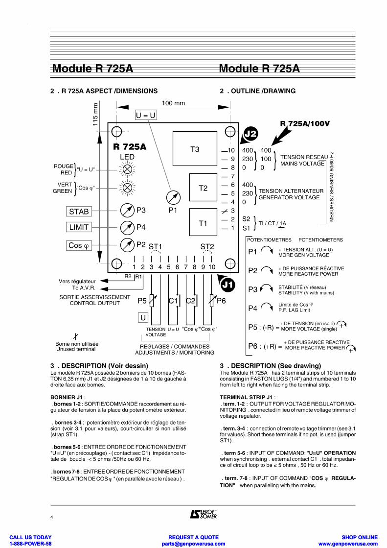
2 . R 725A ASPECT /DIMENSIONS
3 . DESCRIPTION (Voir dessin)Le modèle R 725A possède 2 borniers de 10 bornes (FAS-TON 6,35 mm) J1 et J2 désignées de 1 à 10 de gauche àdroite face aux bornes.
BORNIER J1 : . bornes 1-2 : SORTIE/COMMANDE raccordement au ré-gulateur de tension à la place du potentiomètre extérieur.
. bornes 3-4 : potentiomètre extérieur de réglage de ten-sion (voir 3.1 pour valeurs), court-circuiter si non utilisé(strap ST1).
. bornes 5-6 : ENTREE ORDRE DE FONCTIONNEMENT"U =U" (en précouplage) - ( contact sec C1) impédance to-tale de boucle < 5 ohms /50Hz ou 60 Hz.
. bornes 7-8 : ENTREE ORDRE DE FONCTIONNEMENT"REGULATION DE COS ϕ " (en parallèle avec le réseau ) .
2 . OUTLINE /DRAWING
3 . DESCRIPTION (See drawing)The Module R 725A has 2 terminal strips of 10 terminalsconsisting in FASTON LUGS (1/4") and mumbered 1 to 10from left to right when facing the terminal strip.
TERMINAL STRIP J1 : . term. 1-2 : OUTPUT FOR VOLTAGE REGULATOR MO-NITORING . connected in lieu of remote voltage trimmer ofvoltage regulator.
. term. 3-4 : connection of remote voltage trimmer (see 3.1for values). Short these terminals if no pot. is used (jumperST1).
. term 5-6 : INPUT OF COMMAND: "U=U" OPERATIONwhen synchronising . external contact C1 . total impedan-ce of circuit loop to be ≤ 5 ohms , 50 Hz or 60 Hz.
. term. 7-8 : INPUT OF COMMAND "COS ϕ REGULA-TION" when paralleling with the mains.
4
Module R 725AModule R 725A
10987654321
4002300
4002300
S1S2
}
}}
T3
T2
T1
1 2 3 4 5 6 7 8 9 10
LED
P3
P4
P1
ST1 ST2
TENSION RESEAUMAINS VOLTAGE
TENSION ALTERNATEURGENERATOR VOLTAGE
ROUGERED
VERT GREEN
"U = U"
"Cos ϕ"
}}
J1
P5 C1 C2 P6
UTENSIONVOLTAGE
U = U "Cos ϕ" "Cos ϕ"
J2
TI / CT / 1ALIMIT
Vers régulateurTo A.V.R.
P1
P2
P3
P4
P5 : (-R) =
P6 : (+R) =
+ TENSION ALT. (U = U)MORE GEN VOLTAGE
+ DE PUISSANCE RÉACTIVEMORE REACTIVE POWER
STABILITÉ (// réseau)STABILITY (// with mains)
Limite de Cos ϕP.F. LAG Limit
+ DE TENSION (en isolé) MORE VOLTAGE (single)
+ DE PUISSANCE RÉACTIVE MORE REACTIVE POWER
U = U
100 mm11
5 m
m
ME
SU
RE
S /
SE
NS
ING
50/
60 H
z
POTENTIOMETRES POTENTIOMETERS
+
+REGLAGES / COMMANDESADJUSTMENTS / MONITORING
SORTIE ASSERVISSEMENTCONTROL OUTPUT
P2Cos ϕ
STAB
R2 R1
Borne non utiliséeUnused terminal
4001000 }
R 725A/100V
R 725A
CALL US TODAY 1-888-POWER-58
REQUEST A QUOTE [email protected]
SHOP ONLINE www.genpowerusa.com
CALL US TODAY 1-888-POWER-58
REQUEST A QUOTE [email protected]
SHOP ONLINE www.genpowerusa.com
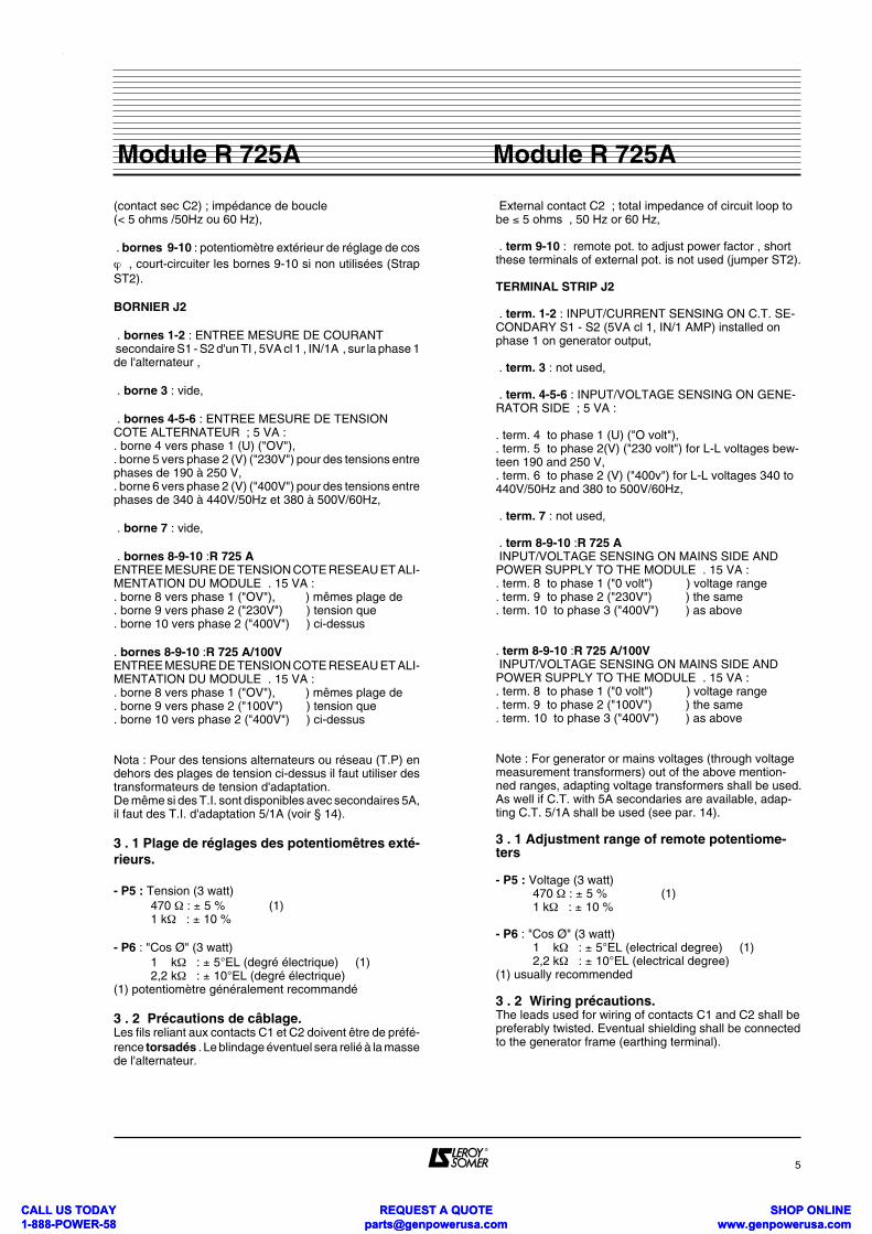
(contact sec C2) ; impédance de boucle (< 5 ohms /50Hz ou 60 Hz),
. bornes 9-10 : potentiomètre extérieur de réglage de cosϕ , court-circuiter les bornes 9-10 si non utilisées (StrapST2).
BORNIER J2
. bornes 1-2 : ENTREE MESURE DE COURANT secondaire S1 - S2 d'un TI , 5VA cl 1 , IN/1A , sur la phase 1de l'alternateur ,
. borne 3 : vide,
. bornes 4-5-6 : ENTREE MESURE DE TENSIONCOTE ALTERNATEUR ; 5 VA :. borne 4 vers phase 1 (U) ("OV"),. borne 5 vers phase 2 (V) ("230V") pour des tensions entrephases de 190 à 250 V,. borne 6 vers phase 2 (V) ("400V") pour des tensions entrephases de 340 à 440V/50Hz et 380 à 500V/60Hz,
. borne 7 : vide,
. bornes 8-9-10 :R 725 AENTREE MESURE DE TENSION COTE RESEAU ET ALI-MENTATION DU MODULE . 15 VA :. borne 8 vers phase 1 ("OV"), ) mêmes plage de . borne 9 vers phase 2 ("230V") ) tension que. borne 10 vers phase 2 ("400V") ) ci-dessus
. bornes 8-9-10 :R 725 A/100VENTREE MESURE DE TENSION COTE RESEAU ET ALI-MENTATION DU MODULE . 15 VA :. borne 8 vers phase 1 ("OV"), ) mêmes plage de . borne 9 vers phase 2 ("100V") ) tension que. borne 10 vers phase 2 ("400V") ) ci-dessus
Nota : Pour des tensions alternateurs ou réseau (T.P) endehors des plages de tension ci-dessus il faut utiliser destransformateurs de tension d'adaptation.De même si des T.I. sont disponibles avec secondaires 5A,il faut des T.I. d'adaptation 5/1A (voir § 14).
3 . 1 Plage de réglages des potentiomêtres exté-rieurs.
- P5 : Tension (3 watt) 470 Ω : ± 5 % (1) 1 kΩ : ± 10 %
- P6 : "Cos Ø" (3 watt) 1 kΩ : ± 5°EL (degré électrique) (1) 2,2 kΩ : ± 10°EL (degré électrique)(1) potentiomètre généralement recommandé
3 . 2 Précautions de câblage.Les fils reliant aux contacts C1 et C2 doivent être de préfé-rence torsadés . Le blindage éventuel sera relié à la massede l'alternateur.
External contact C2 ; total impedance of circuit loop tobe ≤ 5 ohms , 50 Hz or 60 Hz,
. term 9-10 : remote pot. to adjust power factor , shortthese terminals of external pot. is not used (jumper ST2).
TERMINAL STRIP J2
. term. 1-2 : INPUT/CURRENT SENSING ON C.T. SE-CONDARY S1 - S2 (5VA cl 1, IN/1 AMP) installed onphase 1 on generator output,
. term. 3 : not used,
. term. 4-5-6 : INPUT/VOLTAGE SENSING ON GENE-RATOR SIDE ; 5 VA :
. term. 4 to phase 1 (U) ("O volt"),
. term. 5 to phase 2(V) ("230 volt") for L-L voltages bew-teen 190 and 250 V,. term. 6 to phase 2 (V) ("400v") for L-L voltages 340 to440V/50Hz and 380 to 500V/60Hz,
. term. 7 : not used,
. term 8-9-10 :R 725 A INPUT/VOLTAGE SENSING ON MAINS SIDE ANDPOWER SUPPLY TO THE MODULE . 15 VA :. term. 8 to phase 1 ("0 volt") ) voltage range. term. 9 to phase 2 ("230V") ) the same. term. 10 to phase 3 ("400V") ) as above
. term 8-9-10 :R 725 A/100V INPUT/VOLTAGE SENSING ON MAINS SIDE ANDPOWER SUPPLY TO THE MODULE . 15 VA :. term. 8 to phase 1 ("0 volt") ) voltage range. term. 9 to phase 2 ("100V") ) the same. term. 10 to phase 3 ("400V") ) as above
Note : For generator or mains voltages (through voltagemeasurement transformers) out of the above mention-ned ranges, adapting voltage transformers shall be used.As well if C.T. with 5A secondaries are available, adap-ting C.T. 5/1A shall be used (see par. 14).
3 . 1 Adjustment range of remote potentiome-ters
- P5 : Voltage (3 watt) 470 Ω : ± 5 % (1) 1 kΩ : ± 10 %
- P6 : "Cos Ø" (3 watt) 1 kΩ : ± 5°EL (electrical degree) (1) 2,2 kΩ : ± 10°EL (electrical degree)(1) usually recommended
3 . 2 Wiring précautions.The leads used for wiring of contacts C1 and C2 shall bepreferably twisted. Eventual shielding shall be connectedto the generator frame (earthing terminal).
5
Module R 725AModule R 725A
CALL US TODAY 1-888-POWER-58
REQUEST A QUOTE [email protected]
SHOP ONLINE www.genpowerusa.com
CALL US TODAY 1-888-POWER-58
REQUEST A QUOTE [email protected]
SHOP ONLINE www.genpowerusa.com
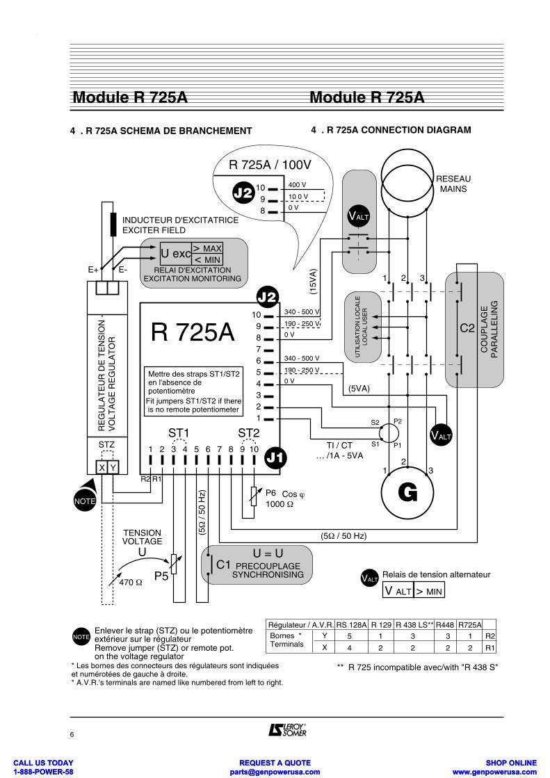
4 . R 725A SCHEMA DE BRANCHEMENT 4 . R 725A CONNECTION DIAGRAM
6
Module R 725AModule R 725A
C1P5
P6
1 2 3 4 5 6 7 8 9 10
123456789
10
1
1
2
2
3
3
INDUCTEUR D'EXCITATRICEEXCITER FIELD
RE
GU
LAT
EU
R D
E T
EN
SIO
N -
V
OLT
AG
E R
EG
ULA
TO
R
E+ E-
U exc > MAX< MIN
X Y
STZ
TENSIONVOLTAGE
U
(5Ω
/ 50
Hz)
U = UPRECOUPLAGE
SYNCHRONISING
(5Ω / 50 Hz)
Cos ϕ
R 725AMettre des straps ST1/ST2en l'absence depotentiomètre
Fit jumpers ST1/ST2 if there is no remote potentiometer
ST1 ST2
J1
J2 (15V
A)
340 - 500 V
190 - 250 V
0 V
340 - 500 V
190 - 250 V
0 V(5VA)
RESEAUMAINS
VALT
C2
UT
ILIS
AT
ION
LO
CA
LELO
CA
L U
SE
R
S2
S1
G
P1
P2
VALTTI / CT
… /1A - 5VA
CO
UP
LAG
EP
AR
ALL
ELI
NG
NOTE
NOTE Enlever le strap (STZ) ou le potentiomètreextérieur sur le régulateurRemove jumper (STZ) or remote pot.on the voltage regulator
Relais de tension alternateurVALT
V ALT > MIN
RELAI D'EXCITATIONEXCITATION MONITORING
* Les bornes des connecteurs des régulateurs sont indiquéeset numérotées de gauche à droite.* A.V.R.'s terminals are named like numbered from left to right.
** R 725 incompatible avec/with "R 438 S"
R2 R1
Régulateur / A.V.R. RS 128A R 129 R 438 LS** R448 R725ABornes *Terminals
R2
R1
5
4
1
2
3
2
3
2
1
2
Y
X
1000 Ω
470 Ω
89
10J2400 V
10 0 V
0 V
R 725A / 100V
CALL US TODAY 1-888-POWER-58
REQUEST A QUOTE [email protected]
SHOP ONLINE www.genpowerusa.com
CALL US TODAY 1-888-POWER-58
REQUEST A QUOTE [email protected]
SHOP ONLINE www.genpowerusa.com
5 . FONCTIONNEMENT
Suivant le mode imposé par l'état des contacts extérieurs(désignés par C1 pour la fonction"U=U" et C2 pour la fonc-tion "Cos ϕ "). L'état fermé des contacts est signalé par desLED.En l'absence de tension réseau aux bornes 8-9-10 de J2 lemodule est inerte (fonctionnement en régulation de ten-sion).En l'absence de tension aux bornes de l'alternateur (à l'ar-rêt ou désexcité), nous recommandons pour la sécuritédu personnel de couper l'alimentation/détection de ten-sion réseau, par exemple par un relais de tension alimentécôté alternateur (U ALT sur schéma de principe, U ALT < 25 % de la tension nominale).
C1 = 0 . ouvert C1 = 1 . fermé LED rouge C2 = 0 . ouvert C2 = 1 . fermé LED verte A = fonctionnement en REGUL. DE TENSION, (module inerte)B = fonctionnement en EGALISATEUR (U=U),C = fonctionnement en REGUL. COS ϕ .
Si la 3ème FONCTION (U=U) n'est pas utilisée, relier les 2entrées de détection de tension du module en parallèle etles alimenter côté alternateur.
6 . REGLAGES
6.1 . PLAGES ET CONDITIONS DE FONCTIONNEMENT6.1.1 . 2EME FONCTION . REGULATION DE COS ϕAvec le branchement indiqué, le potentiomètre interne P2de réglage de Cos ϕ permet de couvrir de Cos ϕ = 0,95 AV(désexcité . absorbant de la puissance réactive) à cos ϕ = 0,65 AR (surexcité . fournissant de la puissance ré-active)..Un potentiométre P4 (Limit) permet de limiter le cos ϕ extrè-me, par ex. 0,8 AR.On obtient Cos ϕ = 1 à environ 1/3 de la plage de réglage..Précision de régulation : ± 2° ELECTRIQUE pour un cou-rant secondaire TI de 1A pour des variations de tension duréseau ± 10%. ± 10° EL. pour un courant secondaire de 0,1 A. Plage de réglage du potentiomètre extérieur de réglage decos ϕ, P6 (§ 3.2).
6.1.2 . 3ème FONCTION . EGALISATION DES TEN-SIONS AVANT COUPLAGE (U=U)
Fonctionne pour un écart initial de tension jusqu'à 10 % en-tre l'alternateur en solo et le réseau.Le potentiomètre intérieur de tarage P1 ((U=U) permetd'égaliser les 2 tensions avant couplage, dans les condi-tions normales de synchronisation, à mieux que 2 % près.
5 . OPERATION PRINCIPLE
The module is operating according to the mode imposed byexternal contacts (named C1 for equalizer function "U=U"and C2 for power factor "Cos ϕ " régulation). Closing of thecontacts is signalled by LED.When the mains voltage is not supplied to terminal 8-9-10on terminal strip J2, the module is inactive (operating as avoltage regulator).For the case where the generator is supposed to deliverno voltage (stopped or disenergized), we recommand forlife safety of personnel to switch off the supply to termi-nals 7-8-9 of J2 by using for example a voltage relayconnected across generator output (U ALT on principle dia-gram, U ALT < 25 % of rated voltage). C1 = 0 . open C1 = 1 . closed red LED C2 = 0 . open C2 = 1 . closed green LED A = operating as a VOLTAGE REGULATOR, (module not acting)B = operating as a VOLTAGE EQUALIZER (U=U)C = operating as a POWER FACTOR REGULATOR (Cos ϕ)
Whenever the 3rd FUNCTION (U=U) is not used, connectthe 2 voltage sensing inputs of the module in parallel andconnect them on generator side.
6 . ADJUSTMENTS
6.1 . OPERATING RANGES AND CONDITIONS6.1.1 . 2nd FUNCTION . POWER FACTOR (cos ϕ ) REGULATIONWhen connected according to the diagram, the internal po-tentiometer P2 (Cos ϕ ) enables to adjust the power factorfrom P.F. = 0,95 LEAD (underexcited . absorbing reactivepower) to P.F. = 0,65 LAG (overexcited . supplying reactivepower).Potentiometer P4 (P.F. Limit) enables to set the lowest Lag. P.F. (i.e. 0,8)P.F. = 1 is achieved at about 1/3 of adjustment range of pot. P2.Accuracy = adjusted phase shift ± 2° ELECTRICAL with aC.T. secondary current of 1A and mains voltage varying wi-thin ± 10 %. ± 10° EL. with a C.T. secondary current of 0,1 A.Adjustment range with external pot. P6 (§ 3.2).
6.1. 2 . 3rd FUNCTION . EQUALIZATION OF VOL-TAGES WHEN SYNCHRONISING (U = U)
Operates up to 10% voltage difference between the gene-rator running single and the mains voltage.The internal OFFSET potentiometer P1 (U =U) enables toequalize the 2 voltages when syncrhonising with a preci-sion better than 2 %.
7
Module R 725AModule R 725A
C 20 1
C 0 A C1 1 B C
CALL US TODAY 1-888-POWER-58
REQUEST A QUOTE [email protected]
SHOP ONLINE www.genpowerusa.com
CALL US TODAY 1-888-POWER-58
REQUEST A QUOTE [email protected]
SHOP ONLINE www.genpowerusa.com
6.2 . PROCEDURE DE REGL AGE DE MISE ENROUTE6.2.1 . VERIFICATIONS PRELIMINAIRESIl faut d'abord s'assurer que le système d'excitation d'origi-ne de la machine a été réglé pour fonctionner sans anoma-lie dans toute la plage de variation de tension du réseaupour le cos ϕ désiré (voir notice correspondante).EXCITATION COMPOUND (ACTR . RBC) : le compounddoit être réglé pour que la tension en solo puisse monter à laplus haute tension en marche parallèle avec le réseau (p.ex . 430 V pour 400 V nominal). Vérifier également que lerégulateur de tension permet de descendre à la tension laplus basse (p. ex . 370 V pour 400V nominal).EXCITATION SHUNT + BOOSTER: le booster (transfo decourant) doit être court-circuité en couplage réseau ou sonaction réduite par un limiteur/moniteur de booster.POUR TOUS LES REGULATEURS, vérifier le réglage duseuil de protection de sous-vitesse (ou du LAM) : il doit être réglé 2 Hz en-desous de la fréquence la plus bas-se pour laquelle le coupleur autorise le couplage.La STABILITE du régulateur de tension doit être réglée enfonctionnement solo.
6.2.2 . REGLAGE DE TENSION EN SOLOPotentiomètre extérieur P5 réglé au milieu.Régler la tension de l'alternateur par le potentiomètre in-terne de tension du régulateur.
6.2.3 . EGALISATION DES TENSIONS AVANT COU-PLAGEAppareils utilisés : tension réseau/alternateur = voltmètrenumérique 500 V. Tension d'excitation (Uexc) = voltmètre analogique cal.30/50 V cc.Démarrer le groupe électrogène et régler la vitesse pourse mettre dans les conditions normales de couplage.Fermer le contact C1 : la LED rouge doit s'allumer.SI LA TENSION CHUTE OU "MONTE AU PLAFOND" :ERREUR DE RACCORDEMENT ENTRE LE REGULA-TEUR DE TENSION ET LE MODULE . STOPPER ETPERMUTER LES 2 FILS ARRIVANT AUX BORNES 1 et 2DU BORNIER J1 DU Module R 725A .Mesurer alternativement la tension du réseau et celle del'alternateur avec le même voltmètre.Réduire l'écart en agissant sur le potentiomètre P1 dumodule (U=U).Si la tension de l'alternateur est instable, observer alors latension d'excitation Uexc et agir sur le potentiomètre P3de réglage de STABILITE du Module R 725A .
6.2.4 . REGLAGE DU COS ϕPositions initiales :- potentiomètre extérieur de cos Ø (P6) = au milieu,- potentiomètre interne (P2) au 1/4 de sa course à partir dela gauche,- potentiomètre P4 (Limit) à fond à droiteSYNCHRONISER ET COUPLER,La LED VERTE DOIT S'ALLUMER.
SI AU MOMENT DU COUPLAGE LE COURANT DE SOR-TIE DE L'ALTERNATEUR MONTE BRUSQUEMENT AUNE VALEUR ELEVEE OU SI LA TENSION D'EXCITA-TION S'ECROULE, DECOUPLER IMMEDIATEMENT :
6.2. ADJUSTMENT PROCEDURE COMMISIONNING6.2.1 . PRELIMINARY CHECKSAt first ensure that the excitation system of the machine hasbeen properly adjusted in order so operate in the wholevoltage variation range of the mains at the requested po-wer factor.( see advisable leaftet.)COMPOUND EXCITATION (ACTR . RBC) : the com-pound system must be adjusted high enough to be able tooperate single on load at the highest main voltage (i.e. 430V for rated 400 V). Check also if the voltage regulator ena-bles to drop the voltage to the lowest mains voltage level(i.e. 370V for rated 400 V).SHUNT + BOOSTER EXCITATION : the booster (currenttransformer) shall be either short-circuited when parallelingwith the mains, or its action shall be reduced by a booster li-mitor/ monitor.ON ALL AVRS, check the setting of underspeed protectionor LAM : the threshold level must be adjusted 2 Hz belowthe lowest frequency for which the synchronizer allows pa-ralleling.The STABILITY of the voltage regulator must be set whenoperating single.6.2.2. ADJUSTMENT OF VOLTAGE IN SINGLE OPERA-TION Remote potentiometer P5 in middle position.Adjust the generator's output voltage by moving the inter-nal voltage adjust. pot. of the voltage regulator.
6.2.3 . EQUALIZATION OF VOLTAGES WHEN SYN-CHRONISINGApparatus = mains/generator voltages : digital voltmeter500 V.Excitation voltage (Uexc) : analogical index voltmeter 30/50V DC.Start the genset and adjust speed to meet normal synchro-nising conditions.Close contact C1 : the red LED should light up.IF THE GENERATOR VOLTAGE DROPS OR RAISESFAR FROM MAINS VOLTAGE : BAD CONNECTIONBETWEEN THE AVR AND THE MODULE . STOP ANDTRANSPOSE THE 2 LEADS CONNECTED ON TERMI-NALS 1 and 2 OF TERMINAL STRIP J1 ON MODULE R 725A.Measure alternatively voltages on mains and generator si-de with the same voltmeter.Reduce difference by moving potentiometer P1 (U=U) onthe module.If the genrator voltage is unstable, adjust on potentiome-ter P3 on the module, observing the excitation voltageUexc, until stabilisation.
6.2.4 . POWER FACTOR (cos ϕ) ADJUSTMENTInitial settings =- external power factor pot. P6 = middle,- internal power factor pot. P2 = 1/4 of range, when startingfully anticlockwise.- internal pot (Limit) P4 fully clockwise. SWITCH ON PARALLEL WHEN SYNCHRONISED The green LED should light up.IF JUST AFTER SWITCHING ON THE LINE CURRENTRISE TO A RATHER HIGH VALUE OR IF THE EXCITATION VOLTAGE DROPS, SWITCH OFF IMME-DIATELY AND STOP GENSET :
8
Module R 725AModule R 725A
CALL US TODAY 1-888-POWER-58
REQUEST A QUOTE [email protected]
SHOP ONLINE www.genpowerusa.com
CALL US TODAY 1-888-POWER-58
REQUEST A QUOTE [email protected]
SHOP ONLINE www.genpowerusa.com
ERREUR DE BRANCHEMENT (PHASES) OU TI A L'EN-VERS (PERMUTER LES 2 ARRIVEES SECONDAIRE S1S2), . charger le groupe en augmentant la vitesse (+ kW) et ré-gler à 60 % de la charge nominale (kW), . régler au cos ϕ extrème désiré par le potentiomètre in-terne P 4 (Limite) : on augmente la puissance réactivefournie (= diminue le cos ϕ ) en tournant P2 en sens horaire(voir nota), . si on ne peut pas obtenir le cos ϕ désiré = ERREUR DEBRANCHEMENT (PHASES), . INSTABILITE := agir sur le potentiomètre P3 et éventuel-lement sur le potentiomètre STABILITÉ du régulateur. . Régler (+kW) 90% de la charge nominale (kW) . Régler le cos ϕ nominal à l'aide du pot P2 (cos ϕ)NOTA : 1) si on ne dispose pas de phasemètre ou "cosphimètre", ilfaut calculer le courant stator (IS) à obtenir pour le cos ϕ désiré kW = indication wattmètre (kW), U RESEAU = tension réelle réseau (V)
2) réglage de cos ϕ = 1 : c'est à cos ϕ = 1 que le courantstator Is est minimum pour une puissance active constan-te (kW) : chercher le minimum.
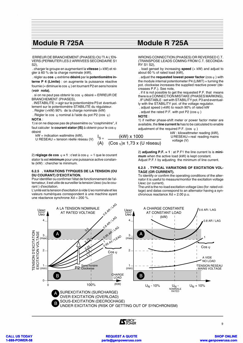
6.2.5 . VARIATIONS TYPIQUES DE LA TENSION (OUDU COURANT) D'EXCITATION.Pour identifier ou confirmer l'état de fonctionnement de l'al-ternateur, il est utile de surveiller la tension Uexc (ou le cou-rant ) d'excitation.L'unité est la tension d'excitation à vide U eo nominale et lesvaleurs numériques correspondent à une machine ayantune réactance synchrone Xd = 200 %.
WRONG CONNECTION (PHASES) OR REVERSED C.T.(TRANSPOSE LEADS COMING FROM C.T. SECONDA-RY S1 S2), . load genset by increasing speed (+ kW) and adjust toabout 60 % of rated load (kW), . adjust the requested lowest power factor (cos ϕ ) withthe module internal potentiometer P4 (LIMIT) = turning thepot. clockwise increases the supplied reactive power (de-creases P.F.). See note, . if it is not possible to get the requested P.F. that meansthere is a CONNECTION MISTAKE (PHASES MARKING), . IF UNSTABLE : set with STABILITY pot. P3 and eventual-ly with the STABILITY pot. of the voltage regulator. . adjust speed (+kW) to reach 90% of rated kW . adjust the rated P.F. with pot P2 (cos ϕ )NOTE :1) if neither phase-shift meter or power factor meter areavailable, the line current Is has to be calculated to enableadjustment of the required P.F. (cos ϕ )
kW : kilowattmeter reading (kW), U RESEAU = real reading mains voltage (V)
2) adjusting P.F. = 1 : at P.F1 the line current Is is mini-mum when the active load (kW) is kept constant.Adjust P.F.1 by adjusting the minimum of line current.
6.2.5 . TYPICAL VARIATIONS OF EXCITATION VOL-TAGE (OR CURRENT).To identify or confirm the operating conditions of the alter-nator it is useful to measure/monitor the excitation voltageUexc (or current).The unit is the no-load excitation voltage Ueo (for rated vol-tage) and datas correspond to an alternator having a syn-chronous reactance Xd = 2.00 p.u.
9
Module R 725AModule R 725A
IS = (kW) x 1000
(A) (Cos ϕ)x 1,73 x (U réseau)
0
1(min)
2
3(max)
4
A LA TENSION NOMINALEAT RATED VOLTAGE
UexcUeo
0 100%
CHARGELOAD
3.5
2.75
2.25
1.9
1.7
0.6 AR / L
AG
0.8 AR / L
AG
0.95 AR / LAG
1
0.95 AV / LEAD}
Cos ϕ
P2Sens horaireClockwiseT
EN
SIO
N D
'EX
CIT
AT
ION
EX
CIT
AT
ION
VO
LTA
GE
1(min)
2
3(max)
4
A CHARGE CONSTANTEAT CONSTANT LOAD
(kW)
UN - 10%
}
Cos ϕ
(KW)
TENSION RESEAUMAINS VOLTAGE
0.6 AR / LAG
0.8 AR / LAG
1
A VIDENO LOAD
UN -NOMINALE
RATED
UN + 10%
A
B
A
B
SUREXCITATION (SURCHARGE) OVER EXCITATION (OVERLOAD) SOUS-EXCITATION (DECROCHAGE) UNDER EXCITATION (RISK OF GETTING OUT OF SYNCHRONISM)
UexcUeo
A
B
CALL US TODAY 1-888-POWER-58
REQUEST A QUOTE [email protected]
SHOP ONLINE www.genpowerusa.com
CALL US TODAY 1-888-POWER-58
REQUEST A QUOTE [email protected]
SHOP ONLINE www.genpowerusa.com
7 . PROTECTIONS SPECIFIQUES A LA MAR-CHE EN PARALLELE AVEC LE RESEAU.
. Relais de tension UALT (présence tension alternateur)permet de couper la détection/alimentation du module àl'arrêt : SECURITE DU PERSONNEL. . relais de tension différentielle (OU COUPLEUR)(U RESAU . U ALTERNATEUR) : interdiction de couplagepour écart trop important, . relais à MAXI D'EXCITATION (surcharge) et MINI D'EX-CITATION (danger de décrochage), tension ou courant cc, . relais à MAXI de COURANT STATOR (THERMIQUE) ouSONDES THERMIQUES (surcharge stator), . MICROCOUPURES : tous les moyens existants disponibles doivent être utilisés pour empêcher le recouplage ouforcer le découplage en cas de microcoupure de tension ré-seau.
ATTENTION : UN SEUL FAUX COUPLAGE AU RESEAUEN OPPOSITION DE PHASE PEUT DETRUIRE L'AL-TERNATEUR. 8 . MARCHE EN PARALLELE AVEC UN OUPLUSIEURS ALTERNATEURS (SEPARESDU RESEAU)
On peut utiliser le même T.I. que pour le Module R 725A =les entrées T.I. du régulateur et du module doivent être re-liées en série, en respectant le sens prévu pour le régula-teur.NOTA : la détection de tension des régulateurs, pour un TIplacé sur la phase 1, doit se faire entre les phases 2 et 3.
9 . COUPLAGE AU RESEAU DE 2 (OU PLUS)ALTERNATEURS FONCTIONNANT EN PA-RALLELE ENTRE-EUX.
(Transfert de charge sans coupure)Il ne faut pas utiliser la 3ème FONCTION (U=U) : le pré-couplage doit se faire en REGULATION DE TENSION (C1et C2 ouverts).Au couplage on passe en REGUL. DE COS ϕ (C2 fermé).Si la tension du réseau varie beaucoup ( >± 5%) il faut alorsutiliser des potentiomètres extérieurs couplés de régla-ge de tension P5 (1 k ohms ) asservis au synchro-cou-pleur (+/ - TENSION).
10 . REGULATION DU COS Ø D'UNE INSTAL-LATION ALIMENTEE PAR LE RESEAU. - Excitation Shunt ou AREP.L'alternateur doit être dimensionné pour fournir toute lapuissance réactive de l'installation (LES CONDENSA-TEURS NORMAUX DE RECALAGE DEVANT ETRE ELI-MINES).
Si le dimensionnement de l'alternateur est insuffisant, il fauten outre installer et régler une résistance de limitation RLen série avec l'inducteur d'excitatrice (RL = env. 2 fois la ré-sistance de l'inducteur), à court-circuiter en marche sépa-rée du réseau.
7 . SPECIFIC PROTECTIONS REQUIREDWHEN PARALLELING WITH THE MAINS. . VOLTAGE relay U ALT (alternator output voltage) to cutoff the mains supply/sensing to the module when the genra-tor is stopped : LIFE SAFETY. . differential voltage (U MAINS . U ALT) relay or synchroni-ser : prohibiting synchronisation for a too large difference, . MAXIMUM EXCITATION (overload) or MINIMUM EXCI-TATION (risk of putting OUT OF SYNCHRONISM) DC vol-tage or current relays. . MAXIMUM LINE CURRENT (THERMICAL) OR THER-MAL SENSORS (stator overload), . MICROBREAKS : all available means shall be applied toimpede reconnection or force switching off in case o f mainsvoltage microbreaks.
CAUTION : THE LIFE DURATION OF A GENERATORPARALLELED WITH MAINS MAY BE ONLY ONECONNECTION COMPLETELY OUT OF PHASE.
8 . PARALLEL OPERATION WITH OTHERGENERATOR(S) (INSULATED FROMMAINS)
The same C.T. as for Module R 725A may be used : the cur-rent sensing imputs of AVR and of the module must beconnected in series, with respect to the connection dia-gram of the voltage regulator.
NOTE : the voltage sensing of the voltage regulator with aC.T. located on phase 1, must be connected across phases2 and 3.
9 . SYNCHRONISING WITH MAINS 2 (OR MO-RE) ALTERNATORS OPERATING IN PARAL-LEL TOGETHER .
(source change-over without break)The 3rd FUNCTION (U=U) shall not be used :synchronisation must be accomplished in VOLTAGE RE-GULATION mode (C1 and C2 open).When switching on the mains (C2 closing), it changes overto POWER FACTOR REGULATION.If the mains voltage varies in a wide range ( >± 5%) the vol-tage equalization must be assumed by external twin po-tentiometers P5 ( 1 k ohms ) monitored by the synchroni-ser system (+/ - voltage command).
10 . MONITORING THE POWER FACTOR OFA PLANT SUPPLIED BY THE MAINS- Shunt or AREP excitation only.The generator should be rated taking into account the who-le reactive power absorbed by the plant (EVENTUAL P.F.COMPENSATION CAPACITORS MUST BE DIS-CONNECTED).
If the rating of generator is too weak to supply the wholereactive power of the plant, an adjustable limiting resistorRL must be connected in series with the exciter field (RL va-lue : = about 2 times the resitance of exciter field), to beshorted when the generator operates single.
10
Module R 725AModule R 725A
CALL US TODAY 1-888-POWER-58
REQUEST A QUOTE [email protected]
SHOP ONLINE www.genpowerusa.com
CALL US TODAY 1-888-POWER-58
REQUEST A QUOTE [email protected]
SHOP ONLINE www.genpowerusa.com
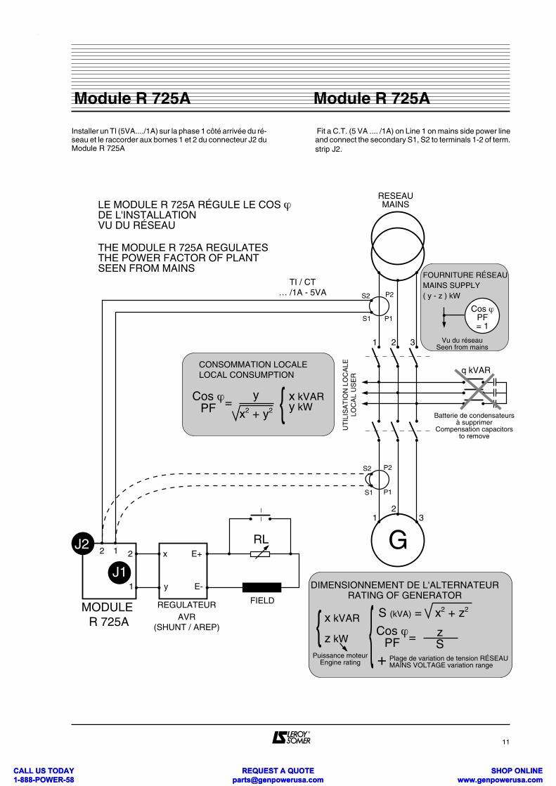
Installer un TI (5VA..../1A) sur la phase 1 côté arrivée du ré-seau et le raccorder aux bornes 1 et 2 du connecteur J2 duModule R 725A
Fit a C.T. (5 VA .... /1A) on Line 1 on mains side power lineand connect the secondary S1, S2 to terminals 1-2 of term.strip J2.
11
Module R 725AModule R 725A
1
1
2
2
3
3
RESEAUMAINS
S1
S2
G
P1
P2
S1
S2
FIELD
q kVAR
Vu du réseauSeen from mains
Batterie de condensateursà supprimer
Compensation capacitorsto remove
LE MODULE R 725A RÉGULE LE COS ϕ DE L'INSTALLATION VU DU RÉSEAU
THE MODULE R 725A REGULATESTHE POWER FACTOR OF PLANTSEEN FROM MAINS
UT
ILIS
AT
ION
LO
CA
LELO
CA
L U
SE
R
TI / CT… /1A - 5VA
Cos ϕPF =
y
x2 + y2 { x kVARy kW
J22 1 2
1
x
y
E+
E-
RL
MODULE R 725A
REGULATEURAVR
(SHUNT / AREP)
S (kVA) = x2 + z2
{ x kVAR
z kW
Puissance moteurEngine rating
{DIMENSIONNEMENT DE L'ALTERNATEUR
RATING OF GENERATOR
Cos ϕPF = z
SPlage de variation de tension RÉSEAUMAINS VOLTAGE variation range+
CONSOMMATION LOCALELOCAL CONSUMPTION
Cos ϕPF= 1
FOURNITURE RÉSEAUMAINS SUPPLY( y - z ) kW
P1
P2
J1
CALL US TODAY 1-888-POWER-58
REQUEST A QUOTE [email protected]
SHOP ONLINE www.genpowerusa.com
CALL US TODAY 1-888-POWER-58
REQUEST A QUOTE [email protected]
SHOP ONLINE www.genpowerusa.com
11 . RECHERCHE DE L'ORIGINE D'UN MAU-VAIS FONCTIONNEMENTLe système complet est supposé avoir déjà fonctionné cor-rectement.
11.1 . VERIFICATION DU REGULATEUR DE TEN-SION(voir notice correspondante) . débrancher les 2 fils de liaison au Module R 725A (bornes1-2 de J1). Court-circuiter les 2 bornes x-y du régulateurprévues pour le raccordement du potentiomètre extérieurde réglage de tension, . faire tourner l'alternateur en solo à vide à sa vitesse nomi-nale. Si la machine donne une tension régulée (vérifier enagissant sur le potentiomètre interne de réglage de tensiondu régulateur), LA PANNE NE VIENT PAS DU REGULA-TEUR DE TENSION
11.2 . VERIFICATION DU MODULE R 725A Vérifier que toutes les informations nécessaires arri-vent aux bornes du module : TENSION RESEAU, TEN-SION ALTERNATEUR, COURANT DU TI (R < 2 ohms ) ,CONTACTS C1 et C2 (R < 5 ohms) ,POTENTIOMETRESEXTERIEURS , et que la liaison au régulateur de tensionn'est pas coupée.SI LE REGULATEUR DE TENSION EST BON ET QUETOUTES LES INFORMATIONS ARRIVENT AU MODU-LE, CELUI-CI EST DEFAILLANT.
12 . REGLAGES STATIQUES DU MODULE R 725A
Voir schéma et liste du matériel ci-après.Les réglages peuvent être effectués sur l'alternateurfonctionnant en solo à vide ou, à l'arrêt, alimenté par leréseau. Déconnecter la liaison du régulateur de tension (bornes 1-2 du connecteur J1 du module). Brancher à ces bornes un voltmètre de préférence digital(cal +/ . 2 V cc), Court-circuiter les bornes correspondantes du régulateur(x-y), Câbler le montage d'essai suivant le schéma.Les interrupteurs et commutateurs peuvent être remplacéspar des prises ou des pinces isolées .La self L (65 mH) n'est nécessaire que pour un préréglage à
cos ϕ ≠ 1 et pour le réglage du cos ϕ AR Limite.
Pour un préréglage à cos ϕ = 1, seule une résitance de27ohms /50 W est nécessaireLa précision des réglages est de l'ordre de ± 2% pour la3ème FONCTION (U=U) et de ± 5° EL pour la 2ème FONC-TION (cos ϕ ) dépendant de la qualité du transformateur detension utilisé.
LA MEME PROCEDURE EST UTILISABLE POURCONTROLER L'ETAT DU MODULE : SI LE MODULE NEREAGIT PAS COMME DECRIT, C'EST QU'IL EST ENDEFAUT.
11 . TRACKING THE ORIGIN OF A MISFUNC-TIONThe complete system is supposed to have been previouslyoperating satisfactorily.
11.1 . CHECKING AUTOMATIC VOLTAGE REGU-LATOR(see aplicable handbook) . disconnect the 2 wires linking to the Module R 725A (Term. 1-2 of J1) and short the 2 term. x-y of the AVR whichare normally for the connection of a remote voltage adjust.pot., . drive the generator at rated speed, operating single at no-load. If the machine supplies a regulated voltage (to bechecked by turning the internal voltage adjustment poten-tiometer) that means that THE MISFUNCTION IS NOTDUE TO THE VOLTAGE REGULATOR.
11.2 . CHECKING MODULE R 725A Check if all the required informations reach the termi-nals of the module : MAINS and GENERATOR VOL-TAGES, C.T. SECONDARY CURRENT (R < 2 ohms),CONTACTS C1 and C2 (R < 5 ohms ), REMOTE POTEN-TIOMETERS , and that connection to the voltage regulatoris not open.IF THE AVR IS GOOD AND ALL INFORMATIONS INCO-ME MODULES TERMINALS IS MEANING THAT THE MO-DULE IS FAILED.
12 . STATIC ADJUSTMENTS ON MODULE R 725A
See diagram and components list here after.The adjustments may be done either on the generatoroperating single at no load, or standing and suppliedby the mains.Disconnect the 2 wires (OUTPUT) linked to the AVR (onterminals 1-2 of terminal strip J1 of the module).Connect to these terminals a DC voltmeter, preferably digi-tal (cal ± 2V DC) and short the 2 terminals x-y of AVR whichwere linked to the module,wire the test assembly according to the diagram,the switches and c/o switch may be replaced by insulatedplugs or clips.The choke (reactor) L ( 65mH) is only necessary for a pre-adjustment at a power factor ≠ 1 et for adjustment of the limitlowest P.F. LAG. for P.F. = 1, only a fixed resistor of 27ohms /50 W is neces-sary.Precision of such static adjustments is about ± 2% for the3rd FUNCTION (U=U) and of ± 5° EL for the 2nd FUNC-TION (P.F., Cos ϕ ), much depending of the quality of avai-lable voltage transformer.
THE SAME PROCEDURE IS APPLICABLE FOR CHEC-KING THE CONDITION OF MODULE : IF THE MODULEIS NOT REACTING AS DESCRIBED, THAT MEANS IT ISFAILED.
12
Module R 725AModule R 725A
CALL US TODAY 1-888-POWER-58
REQUEST A QUOTE [email protected]
SHOP ONLINE www.genpowerusa.com
CALL US TODAY 1-888-POWER-58
REQUEST A QUOTE [email protected]
SHOP ONLINE www.genpowerusa.com
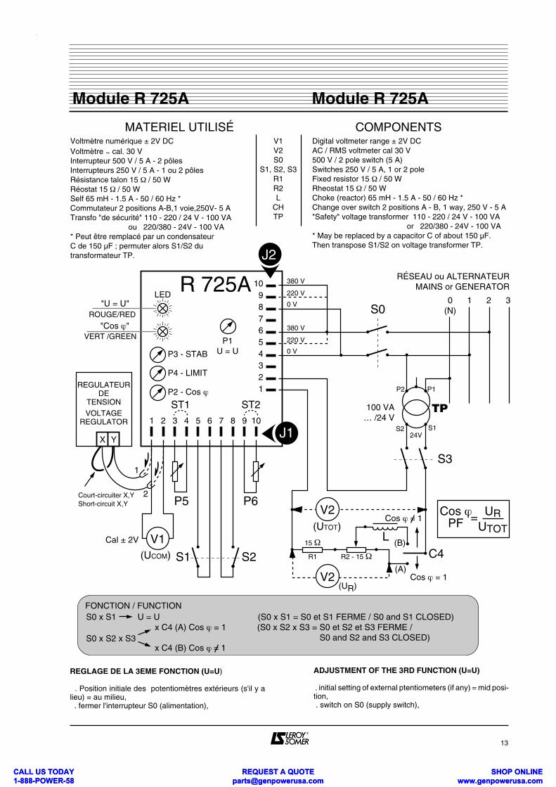
REGLAGE DE LA 3EME FONCTION (U=U)
. Position initiale des potentiomètres extérieurs (s'il y alieu) = au milieu, . fermer l'interrupteur S0 (alimentation),
ADJUSTMENT OF THE 3RD FUNCTION (U=U)
. initial setting of external ptentiometers (if any) = mid posi-tion, . switch on S0 (supply switch),
13
Module R 725AModule R 725A
S2
P5 P6
1 2 3 4 5 6 7 8 9 10
123456789
10
REGULATEURDE
TENSION
X Y
R 725A
ST1 ST2
J1
J2
380 V
220 V
0 VLED
P4 - LIMIT
P2 - Cos ϕ
P1U = U
ROUGE/RED
VERT /GREEN
"U = U"
"Cos ϕ"
VOLTAGEREGULATOR
S1
V1
1
2
(UCOM)
Cal ± 2V
380 V
220 V
0 V
S3
S0
P2 P1
S2
TP100 VA… /24 V
24V
0(N)
1 2 3
V2(UTOT)
(B)C4
15 Ω
R1 R2 - 15 Ω
(A)
L
Cos ϕPF = UR
UTOT
MATERIEL UTILISÉ COMPONENTSVoltmètre numérique ± 2V DCVoltmètre ~ cal. 30 VInterrupteur 500 V / 5 A - 2 pôlesInterrupteurs 250 V / 5 A - 1 ou 2 pôlesRésistance talon 15 Ω / 50 WRéostat 15 Ω / 50 WSelf 65 mH - 1.5 A - 50 / 60 Hz *Commutateur 2 positions A-B,1 voie,250V- 5 ATransfo "de sécurité" 110 - 220 / 24 V - 100 VA ou 220/380 - 24V - 100 VA* Peut être remplacé par un condensateurC de 150 µF ; permuter alors S1/S2 du transformateur TP.
Digital voltmeter range ± 2V DCAC / RMS voltmeter cal 30 V500 V / 2 pole switch (5 A)Switches 250 V / 5 A, 1 or 2 poleFixed resistor 15 Ω / 50 WRheostat 15 Ω / 50 W Choke (reactor) 65 mH - 1.5 A - 50 / 60 Hz *Change over switch 2 positions A - B, 1 way, 250 V - 5 A "Safety" voltage transformer 110 - 220 / 24 V - 100 VA or 220/380 - 24V - 100 VA* May be replaced by a capacitor C of about 150 µF.Then transpose S1/S2 on voltage transformer TP.
V1V2S0
S1, S2, S3R1R2L
CHTP
RÉSEAU ou ALTERNATEURMAINS or GENERATOR
FONCTION / FUNCTIONS0 x S1 U = U (S0 x S1 = S0 et S1 FERME / S0 and S1 CLOSED)
S0 x S2 x S3x C4 (A) Cos ϕ = 1 (S0 x S2 x S3 = S0 et S2 et S3 FERME / S0 and S2 and S3 CLOSED)x C4 (B) Cos ϕ = 1
Court-circuiter X,YShort-circuit X,Y
P3 - STAB
S1
V2 Cos ϕ = 1
Cos ϕ = 1
(UR)
CALL US TODAY 1-888-POWER-58
REQUEST A QUOTE [email protected]
SHOP ONLINE www.genpowerusa.com
CALL US TODAY 1-888-POWER-58
REQUEST A QUOTE [email protected]
SHOP ONLINE www.genpowerusa.com
. fermer l'interrupteur S1 (U=U), . la LED rouge s'allume, . le voltmètre VI indique une tension U COM soit, environ . -1 VOLT, soit environ + 1 V, . en tournant le potentiomètre P1 (U=U) de gauche à droite,la tension UCOM passe d'une de ces valeurs extrèmes àl'autre, . le point de réglage est la position de P1 pour laquelle levoltmètre VI indique une tension qui bascule de (+) à (-) 0,5 VOLT.
REGLAGE DE LA 2EME FONCTION (COS ϕ ) a) réglage de P4 .tourner les potentiomètres P2 (cos ϕ) et P4 (LIMITE) àfond à droite. fermer l'interrupteur S2 ( cos ϕ ), . la LED verte s'allume, . commutateur C4 : B (cos ϕ ≠1), . fermer l'interrupteur S3 (simulation de TI), . régler le cos ϕ limite désiré . tourner le potentiomètre P4 (limite ) jusqu'à la positionpour laquelle le voltmètre V1 indique une tension qui bas-cule de (+) à (-) 0,5 VOLT. b) réglage de P2 (cos ϕ nominal)C4 en position B ou A : régler le cos ϕ nominal désiré, pro-céder avec P2 comme avec P4 précédemment. . ouvrir tous les interrupteurs et raccorder suivant le sché-ma.
13 . REGIME DU NEUTRELe régime du neutre n'a aucune influence sur le fonctionne-ment du module.Par contre, si l'alternateur a un bobinage stator dont lepas est différent de 2/3, et que les neutres du transforma-teur et de l'alternateur sont reliés directement ou par l'inter-médiaire de la terre, il faut installer en série avec le neutreune self de limitation de courant harmonique.Soit X ( ohms ) la réactance de la self et L (HENRY) son in-ductance X = 314 x L à 50 Hz et 377 x L à 60 Hz.Le courant harmonique dans le neutre Ih sera :
U (v)I h = 0,038 x (U TENSION ENTRE PHASES) X (ohms)
AUQUEL VIENDRA S'AJOUTER LE COURANT HOMOPOLAIRE I o DU AUX CHARGES DESEQUILIBREES.
I NEUTRE = V (IO)2 + (IH)2 (Ampères efficaces)
14 . MESURE DE TENSIONS ET COURANTSHORS DES PLAGES STANDARD DU MODU-LE R 725A
On utilise des transformateurs d'adaptation dimensionnéscomme suit:14.1. Transformateurs de tension (TP)Dimensionnement thermique 50 VA - 50/60Hz Tension primaire : tension disponible sur TP ou en bassetension ≠ 230 - 250 V et 380 - 480 V (100 - 110 - 120 - 500 -600V)Tension secondaire : 220 ou 400 V.
. switch on S1 (U=U Command), . the red LED lights up. . the voltmeter V1 indicates a voltage UCOM either about (--1 volt) or about (+ 1 volt).By rotating potentiometer P1 (U=U) dockwise from fully an-tibockwise position, voltage UCOM triggers from one of themaximum negative (or reverse) to the other maximum.The setting position of P1 is that one where the voltmeter V1indicates a voltage changing from (+) to (-) 0,5 VOLT.
ADJUSTMENT OF THE 2ND FUNCTION (COS ϕ ) a) adjustment of P4 . set potentiometers P2 (Cos ϕ) and P4 (LIMIT) fully clock-wise. . close switch S2 (COS ϕ FUNCTION COMMAND), . the green LED lights up, . change over switch in position : B (PF≠1), . switch on S3 (circuit simulating C.T.), . adjust to the required P.F. (no adjustment for P.F. = 1), . rotate potentiometer P4 (LIMIT) until to reach a positionwhere voltmeter V1 indicates a voltage tilting from (+) to (-)0,5 Volt. b) adjustment of P2 (rated P.F.)C4 in position B or A - Adjust the required rated P.F., pro-ceed with pot P2 as préviously with P4.. switch off all the switches and reconnect according rele-vant diagram.
13 . NEUTRAL LINE STATUSThe neutral line status has no influence on the module ope-ration.Adversely, if the winding pitch of the stator winding ofthe alternateur is different from 2/3, and the neutral of themains transformer and of the generator a connected toge-ther either directly or through the carthing circuit, an har-monic current limiting choke (reactor) must be installedin series with the generator neutral connection.If X ( ohms ) is the reactance of the choke and L (HENRY) itsinductance : X = 314 x L at 50 Hz and 377 x L at 60 Hzthe harmonic current in neutral line Ih will be = U(V)I h = 0,038 x (U LINE TO LINE VOLTAGE) X (ohms )
To this current is adding the zero sequence current I o dueto load unbalance (LN loads):
I neutral (Amperes R.M.S.) = V (IO)2 + (IH)2
14 . MEASUREMENT OF VOLTAGES ANDCURRENTS OUT OF STANDARD RANGESOF MODULE R 725 A
Adapting transformers shall be used, rated as follows.
14.1. Voltage transformers (V.T.)Thermal rating 50 VA - 50/60 Hz.Primary voltage : the voltage available from measurementvoltage transformer (HV) or low voltages differing from 200- 250 V or 380 - 480 V (i.e. 100 - 110 - 120 - 500 - 600V) Secondary voltage : 220 or 400 V.
14
Module R 725AModule R 725A
CALL US TODAY 1-888-POWER-58
REQUEST A QUOTE [email protected]
SHOP ONLINE www.genpowerusa.com
CALL US TODAY 1-888-POWER-58
REQUEST A QUOTE [email protected]
SHOP ONLINE www.genpowerusa.com
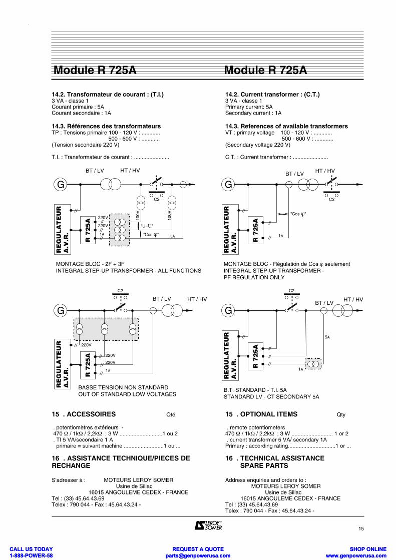
14.2. Transformateur de courant : (T.I.)3 VA - classe 1Courant primaire : 5ACourant secondaire : 1A
14.3. Références des transformateursTP : Tensions primaire 100 - 120 V : ............ 500 - 600 V : ............(Tension secondaire 220 V)
T.I. : Transformateur de courant : .......................
15 . ACCESSOIRES Qté
. potentiomètres extérieurs - 470 Ω / 1kΩ / 2,2kΩ ; 3 W ............................1 ou 2 . TI 5 VA/secondaire 1 A primaire = suivant machine ..........................1 ou ...
16 . ASSISTANCE TECHNIQUE/PIECES DERECHANGE
S'adresser à : MOTEURS LEROY SOMER Usine de Sillac 16015 ANGOULEME CEDEX - FRANCETel : (33) 45.64.43.69 Telex : 790 044 - Fax : 45.64.43.24 -
14.2. Current transformer : (C.T.)3 VA - classe 1Primary current: 5ASecondary current : 1A
14.3. References of available transformersVT : primary voltage 100 - 120 V : ............ 500 - 600 V : ............(Secondary voltage 220 V)
C.T. : Current transformer : .......................
15 . OPTIONAL ITEMS Qty
. remote potentiometers 470 Ω / 1kΩ / 2,2kΩ ; 3 W ........................... 1 or 2 . current transformer 5 VA/ secondary 1A Primary : according rating...............................1 or ...
16 . TECHNICAL ASSISTANCE SPARE PARTS
Address enquiries and orders to : MOTEURS LEROY SOMER Usine de Sillac 16015 ANGOULEME CEDEX - FRANCETel : (33) 45.64.43.69 Telex : 790 044 - Fax : 45.64.43.24 -
15
Module R 725AModule R 725A
C2
1A
100V
"Cos ϕ"
"U=U"
G
HT / HVBT / LV
R 7
25
A
RE
GU
LA
TE
UR
A.V
.R.
100V
220V
220V
MONTAGE BLOC - 2F + 3FINTEGRAL STEP-UP TRANSFORMER - ALL FUNCTIONS
C2
GHT / HVBT / LV
BASSE TENSION NON STANDARDOUT OF STANDARD LOW VOLTAGES
1A
R 7
25
A
RE
GU
LA
TE
UR
A.V
.R.
220V
220V
220V
C2
1A
"Cos ϕ"
G
HT / HVBT / LV
R 7
25
A
RE
GU
LA
TE
UR
A.V
.R.
MONTAGE BLOC - Régulation de Cos ϕ seulementINTEGRAL STEP-UP TRANSFORMER - PF REGULATION ONLY
GHT / HV
BT / LV
R 7
25
A
RE
GU
LA
TE
UR
A.V
.R.
B.T. STANDARD - T.I. 5ASTANDARD LV - CT SECONDARY 5A
C2
5A
1A
5A
CALL US TODAY 1-888-POWER-58
REQUEST A QUOTE [email protected]
SHOP ONLINE www.genpowerusa.com
CALL US TODAY 1-888-POWER-58
REQUEST A QUOTE [email protected]
SHOP ONLINE www.genpowerusa.com
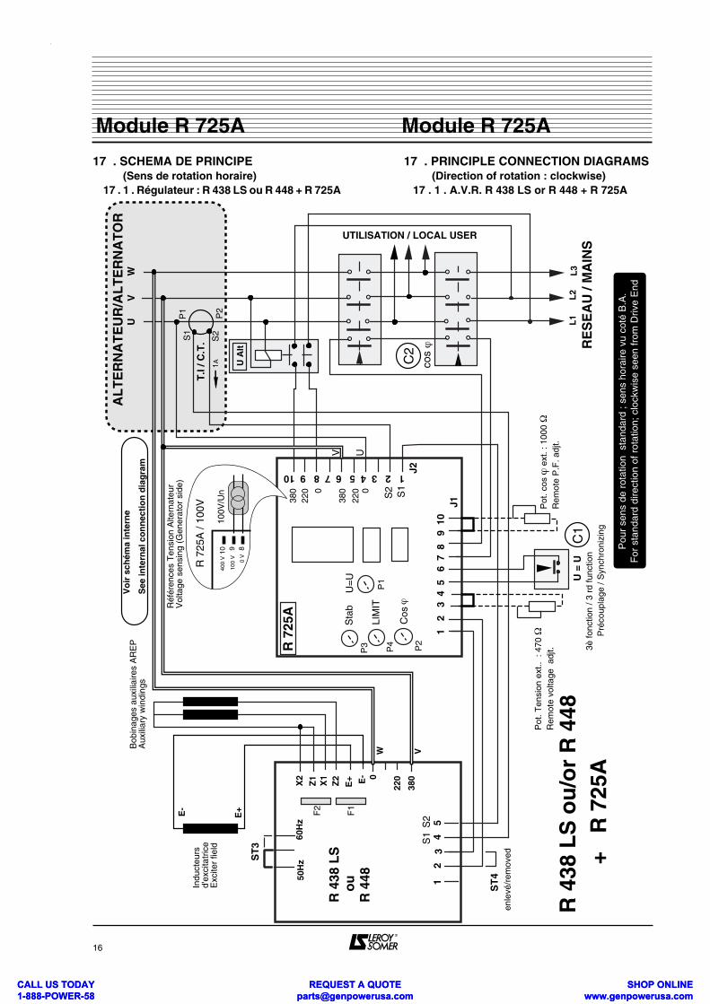
17 . SCHEMA DE PRINCIPE (Sens de rotation horaire) 17 . 1 . Régulateur : R 438 LS ou R 448 + R 725A
17 . PRINCIPLE CONNECTION DIAGRAMS (Direction of rotation : clockwise) 17 . 1 . A.V.R. R 438 LS or R 448 + R 725A
16
Module R 725AModule R 725A
° ° °°
RE
SE
AU
/ M
AIN
S
X2
Z1
X1
Z2
E+ E- 0
220
380
50H
z60
Hz
R 4
38 L
S
ou
R 4
48
ST
3
ST
4en
levé
/rem
oved
U =
U 3
è fo
nctio
n / 3
rd
func
tion
Pré
coup
lage
/ S
ynch
roni
zing
AL
TE
RN
AT
EU
R/A
LT
ER
NA
TO
R
° ° °° L1
UTILISATION / LOCAL USER
F2
F1
Indu
cteu
rs
d'ex
cita
tric
eE
xcite
r fie
ld
Bob
inag
es a
uxili
aire
s A
RE
PA
uxili
ary
win
ding
s
380
220 0
380
220 0
1 2
3
4 5
6
7 8
9
10
R 7
25A
U=
US
tab
Cos
ϕ
1 2 3 4 5 6 7 8 9 10
J1
J2
VU
W
° ° °° L2
L3° ° °°
Pot
. Ten
sion
ext
.. :
470 Ω
Rem
ote
volta
ge a
djt.
12
34
5
Réf
éren
ces
Ten
sion
Alte
rnat
eur
Vol
tage
sen
sing
(G
ener
ator
sid
e)
T.I
/ C.T
.
U A
lt
P2
R 4
38 L
S o
u/o
r R
448
+ R
725
A
P1
Pot
. cos
ϕ e
xt. :
100
0 Ω
Rem
ote
P.F
. adj
t.
C1
C2
cos ϕ
Vo
ir s
chém
a in
tern
e
See
inte
rnal
co
nn
ecti
on
dia
gra
m
S1
S2
LIM
IT
S1
S2
1A
P1
P2
P4
P3
UV
Pou
r se
ns d
e ro
tatio
n s
tand
ard
; sen
s ho
raire
vu
coté
B.A
.F
or s
tand
ard
dire
ctio
n of
rot
atio
n; c
lock
wis
e se
en fr
om D
rive
End
S1
S2
891040
0 V
100
V
0 V
R 7
25A
/ 10
0V
100V
/Un
E+
W V
E-
CALL US TODAY 1-888-POWER-58
REQUEST A QUOTE [email protected]
SHOP ONLINE www.genpowerusa.com
CALL US TODAY 1-888-POWER-58
REQUEST A QUOTE [email protected]
SHOP ONLINE www.genpowerusa.com
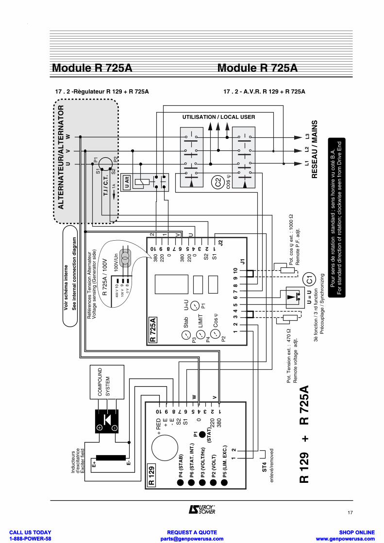
17 . 2 -Règulateur R 129 + R 725A 17 . 2 - A.V.R. R 129 + R 725A
17
Module R 725AModule R 725A
° ° °°
RE
SE
AU
/ M
AIN
S
ST
4en
levé
/rem
oved
U =
U 3
è fo
nctio
n / 3
rd
func
tion
Pré
coup
lage
/ S
ynch
roni
zing
AL
TE
RN
AT
EU
R/A
LT
ER
NA
TO
R
° ° °° L1
Indu
cteu
rs
d'ex
cita
tric
eE
xcite
r fie
ld
380
220 0
380
220 0
1 2
3
4 5
6
7 8
9
10
R 7
25A
1 2 3 4 5 6 7 8 9 10
J1
J2
VU
W
° ° °° L2
L3° ° °°
Pot
. Ten
sion
ext
. : 4
70 Ω
Rem
ote
volta
ge a
djt.
Réf
éren
ces
Ten
sion
Alte
rnat
eur
Vol
tage
sen
sing
(G
ener
ator
sid
e)
T.I
/ C.T
.
U A
lt
P2
R 1
29
+ R
725
A
P1
Pot
. cos
ϕ e
xt. :
100
0 Ω
R
emot
e P
.F. a
djt.
C1
C2
cos ϕ
Vo
ir s
chém
a in
tern
e
See
inte
rnal
co
nn
ecti
on
dia
gra
m
R 1
29
P4
(ST
AB
)
12
1 2 3 4 5 6 7 8 9 10
+ R
ED
+ E - E S2
S1 0
220
380
P1
P6
(ST
AT
. IN
T.)
P3
(VO
LT
/Hz)
P2
(VO
LT
)
P5
(LIM
. EX
C.)
−+C
OM
PO
UN
D
SY
ST
EM
S1
S2
UTILISATION / LOCAL USER
U=
US
tab
Cos
ϕ
LIM
IT
S1
S2
1A
P1
P2
P4
P3
(ST
AT
)
2 1 UV
Pou
r se
ns d
e ro
tatio
n s
tand
ard
; sen
s ho
raire
vu
coté
B.A
.F
or s
tand
ard
dire
ctio
n of
rot
atio
n; c
lock
wis
e se
en fr
om D
rive
End
891040
0 V
100
V
0 V
R 7
25A
/ 10
0V
100V
/Un
E+
W V
E-
CALL US TODAY 1-888-POWER-58
REQUEST A QUOTE [email protected]
SHOP ONLINE www.genpowerusa.com
CALL US TODAY 1-888-POWER-58
REQUEST A QUOTE [email protected]
SHOP ONLINE www.genpowerusa.com
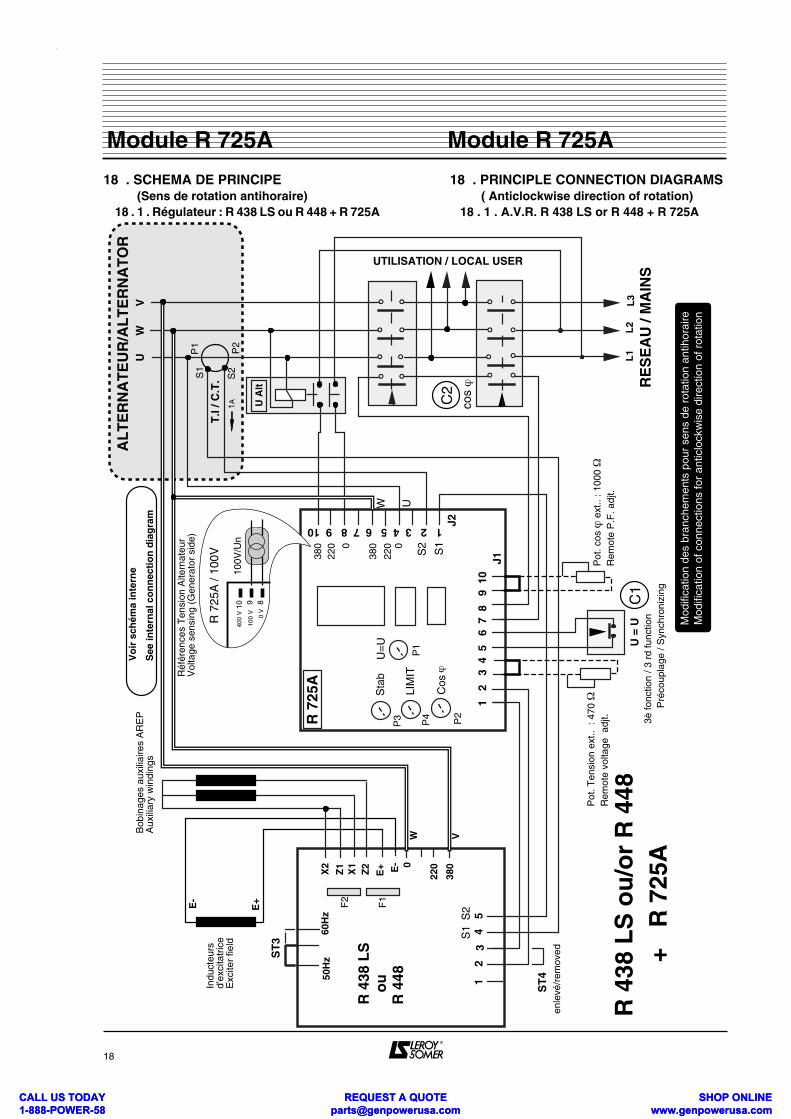
18 . SCHEMA DE PRINCIPE (Sens de rotation antihoraire) 18 . 1 . Régulateur : R 438 LS ou R 448 + R 725A
18 . PRINCIPLE CONNECTION DIAGRAMS ( Anticlockwise direction of rotation) 18 . 1 . A.V.R. R 438 LS or R 448 + R 725A
18
Module R 725AModule R 725A
° ° °°
RE
SE
AU
/ M
AIN
S
X2
Z1
X1
Z2
E+ E- 0
220
380
50H
z60
Hz
R 4
38 L
S
ou
R 4
48
ST
3
ST
4en
levé
/rem
oved
U =
U 3
è fo
nctio
n / 3
rd
func
tion
Pré
coup
lage
/ S
ynch
roni
zing
AL
TE
RN
AT
EU
R/A
LT
ER
NA
TO
R
° ° °° L1
UTILISATION / LOCAL USER
F2
F1
Indu
cteu
rs
d'ex
cita
tric
eE
xcite
r fie
ld
Bob
inag
es a
uxili
aire
s A
RE
PA
uxili
ary
win
ding
s
380
220 0
380
220 0
1 2
3
4 5
6
7 8
9
10
R 7
25A
U=
US
tab
Cos
ϕ
1 2 3 4 5 6 7 8 9 10
J1
J2
VU
W ° ° °° L2
L3° ° °°
Pot
. Ten
sion
ext
.. :
470 Ω
Rem
ote
volta
ge a
djt.
12
34
5
Réf
éren
ces
Ten
sion
Alte
rnat
eur
Vol
tage
sen
sing
(G
ener
ator
sid
e)
T.I
/ C.T
.
U A
lt
P2
R 4
38 L
S o
u/o
r R
448
+ R
725
A
P1
Pot
. cos
ϕ e
xt..
: 100
0 Ω
R
emot
e P
.F. a
djt.
C1
C2
cos ϕ
Vo
ir s
chém
a in
tern
e
See
inte
rnal
co
nn
ecti
on
dia
gra
m
S1
S2
LIM
IT
S1
S2
1A
P1
P2
P4
P3
UW
Mod
ifica
tion
des
bran
chem
ents
pou
r se
ns d
e ro
tatio
n an
tihor
aire
Mod
ifica
tion
of c
onne
ctio
ns fo
r an
ticlo
ckw
ise
dire
ctio
n of
rot
atio
n
S1
S2
891040
0 V
100
V
0 V
R 7
25A
/ 10
0V
100V
/Un
E+
W V
E-
CALL US TODAY 1-888-POWER-58
REQUEST A QUOTE [email protected]
SHOP ONLINE www.genpowerusa.com
CALL US TODAY 1-888-POWER-58
REQUEST A QUOTE [email protected]
SHOP ONLINE www.genpowerusa.com
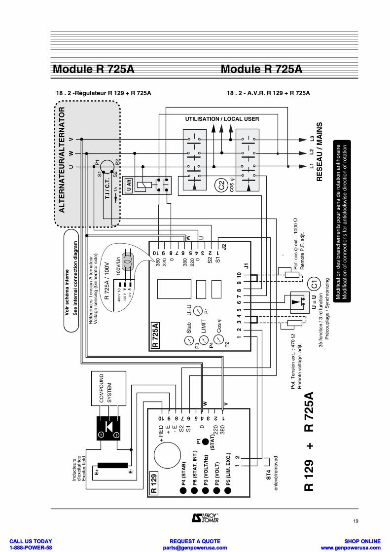
18 . 2 -Règulateur R 129 + R 725A 18 . 2 - A.V.R. R 129 + R 725A
19
Module R 725AModule R 725A
° ° °°
RE
SE
AU
/ M
AIN
S
ST
4en
levé
/rem
oved
U =
U 3
è fo
nctio
n / 3
rd
func
tion
Pré
coup
lage
/ S
ynch
roni
zing
AL
TE
RN
AT
EU
R/A
LT
ER
NA
TO
R
° ° °° L1
Indu
cteu
rs
d'ex
cita
tric
eE
xcite
r fie
ld
380
220 0
380
220 0
1 2
3
4 5
6
7 8
9
10
R 7
25A
1 2 3 4 5 6 7 8 9 10
J1
J2
VU
W ° ° °° L2
L3° ° °°
Pot
. Ten
sion
ext
.. : 4
70 Ω
Rem
ote
volta
ge a
djt.
Réf
éren
ces
Ten
sion
Alte
rnat
eur
Vol
tage
sen
sing
(G
ener
ator
sid
e)
T.I
/ C.T
.
U A
lt
P2
R 1
29
+ R
725
A
P1
Pot
. cos
ϕ e
xt. :
100
0 Ω
Rem
ote
P.F
. adj
t.
C1
C2
cos ϕ
Vo
ir s
chém
a in
tern
e
See
inte
rnal
co
nn
ecti
on
dia
gra
m
R 1
29
P4
(ST
AB
)
12
1 2 3 4 5 6 7 8 9 10
+ R
ED
+ E - E S2
S1 0
220
380
P1
P6
(ST
AT
. IN
T.)
P3
(VO
LT
/Hz)
P2
(VO
LT
)
P5
(LIM
. EX
C.)
−+C
OM
PO
UN
D
SY
ST
EM
S1
S2
UTILISATION / LOCAL USER
U=
US
tab
Cos
ϕ
LIM
IT
S1
S2
1A
P1
P2
P4
P3
(ST
AT
)
UW
Mod
ifica
tion
des
bran
chem
ents
pou
r se
ns d
e ro
tatio
n an
tihor
aire
Mod
ifica
tion
of c
onne
ctio
ns fo
r an
ticlo
ckw
ise
dire
ctio
n of
rot
atio
n
891040
0 V
100
V
0 V
R 7
25A
/ 10
0V
100V
/Un
E+
W V
E-
CALL US TODAY 1-888-POWER-58
REQUEST A QUOTE [email protected]
SHOP ONLINE www.genpowerusa.com
CALL US TODAY 1-888-POWER-58
REQUEST A QUOTE [email protected]
SHOP ONLINE www.genpowerusa.com
MOTEURS LEROY-SOMER 16015 ANGOULÊME CEDEX - FRANCE
338 567 258 RCS ANGOULÊMES.A. au capital de 62 779 000 €
CALL US TODAY 1-888-POWER-58
REQUEST A QUOTE [email protected]
SHOP ONLINE www.genpowerusa.com
CALL US TODAY 1-888-POWER-58
REQUEST A QUOTE [email protected]
SHOP ONLINE www.genpowerusa.com