DKG-217 MANUAL AND REMOTE START UNIT WITH SYNCHROSCOPE · PDF fileREMOTE START UNIT WITH...
26
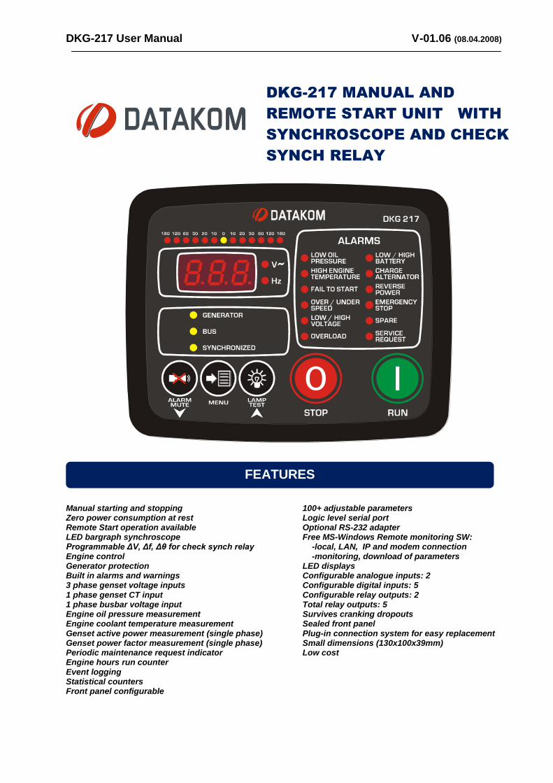
DKG-217 User Manual V-01.06 (08.04.2008) DKG-217 MANUAL AND REMOTE START UNIT WITH SYNCHROSCOPE AND CHECK SYNCH RELAY Manual starting and stopping Zero power consumption at rest Remote Start operation available LED bargraph synchroscope Programmable ΔV, Δf, Δθ for check synch relay Engine control Generator protection Built in alarms and warnings 3 phase genset voltage inputs 1 phase genset CT input 1 phase busbar voltage input Engine oil pressure measurement Engine coolant temperature measurement Genset active power measurement (single phase) Genset power factor measurement (single phase) Periodic maintenance request indicator Engine hours run counter Event logging Statistical counters Front panel configurable 100+ adjustable parameters Logic level serial port Optional RS-232 adapter Free MS-Windows Remote monitoring SW: -local, LAN, IP and modem connection -monitoring, download of parameters LED displays Configurable analogue inputs: 2 Configurable digital inputs: 5 Configurable relay outputs: 2 Total relay outputs: 5 Survives cranking dropouts Sealed front panel Plug-in connection system for easy replacement Small dimensions (130x100x39mm) Low cost FEATURES
Transcript of DKG-217 MANUAL AND REMOTE START UNIT WITH SYNCHROSCOPE · PDF fileREMOTE START UNIT WITH...
DKG-217 User Manual V-01.06 (08.04.2008)
DKG-217 MANUAL AND
REMOTE START UNIT WITH
SYNCHROSCOPE AND CHECK
SYNCH RELAY
Manual starting and stopping Zero power consumption at rest Remote Start operation available LED bargraph synchroscope Programmable ΔV, Δf, Δθ for check synch relay Engine control Generator protection Built in alarms and warnings 3 phase genset voltage inputs 1 phase genset CT input 1 phase busbar voltage input Engine oil pressure measurement Engine coolant temperature measurement Genset active power measurement (single phase) Genset power factor measurement (single phase) Periodic maintenance request indicator Engine hours run counter Event logging Statistical counters Front panel configurable
100+ adjustable parameters Logic level serial port Optional RS-232 adapter Free MS-Windows Remote monitoring SW: -local, LAN, IP and modem connection -monitoring, download of parameters LED displays Configurable analogue inputs: 2 Configurable digital inputs: 5 Configurable relay outputs: 2 Total relay outputs: 5 Survives cranking dropouts Sealed front panel Plug-in connection system for easy replacement Small dimensions (130x100x39mm) Low cost
FEATURES
DKG-217 User Manual V-01.06 (08.04.2008)
- 2 -
Section
1. INSTALLATION 1.1. Introduction to the Control Panel 1.2. Mounting the Unit 1.3. Wiring the Unit
2. INPUTS AND OUTPUTS 3. DISPLAYS
3.1. Led Displays 3.2. Digital Display
4. ALARMS AND WARNINGS 5. MODES OF OPERATION 6. OTHER FEATURES 6.1. Remote start operation 6.2. Synchronization checking 6.3. Sender type selection 6.4. Engine Heating 6.5. Service Request Display 6.6. Engine Hour Meter 6.7. Modem connection 6.8. Remote Monitoring and Programming 7. STATISTICAL COUNTERS 8. MAINTENANCE 9. PROGRAMMING 10. TROUBLESHOOTING 11. DECLARATION OF CONFORMITY 12. TECHNICAL SPECIFICATIONS 13. CONNECTION DIAGRAM
TABLE OF CONTENTS
DKG-217 User Manual V-01.06 (08.04.2008)
- 3 -
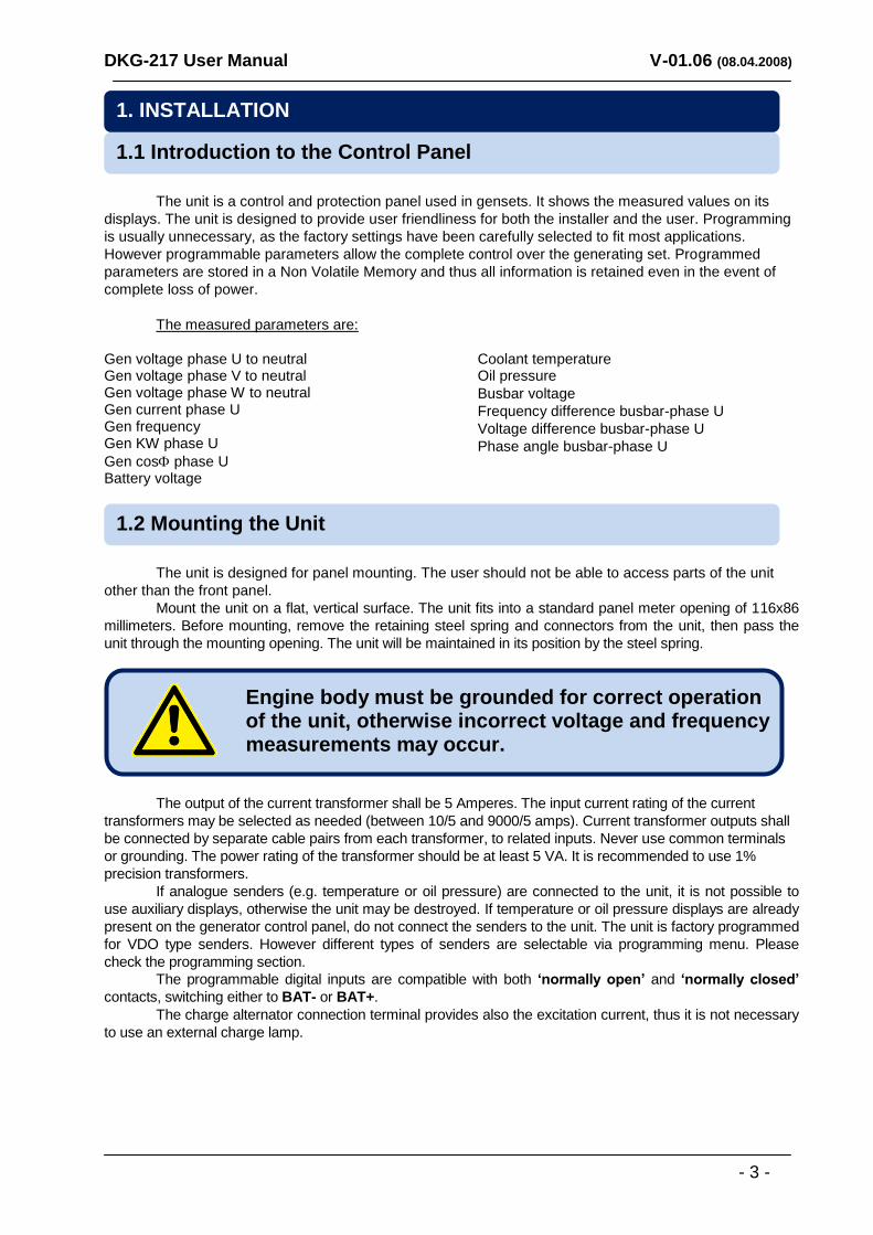
The unit is a control and protection panel used in gensets. It shows the measured values on its
displays. The unit is designed to provide user friendliness for both the installer and the user. Programming
is usually unnecessary, as the factory settings have been carefully selected to fit most applications.
However programmable parameters allow the complete control over the generating set. Programmed
parameters are stored in a Non Volatile Memory and thus all information is retained even in the event of
complete loss of power.
The measured parameters are:
Gen voltage phase U to neutral Gen voltage phase V to neutral Gen voltage phase W to neutral Gen current phase U Gen frequency Gen KW phase U
Gen cos phase U Battery voltage
Coolant temperature Oil pressure
Busbar voltage
Frequency difference busbar-phase U
Voltage difference busbar-phase U
Phase angle busbar-phase U
The unit is designed for panel mounting. The user should not be able to access parts of the unit
other than the front panel.
Mount the unit on a flat, vertical surface. The unit fits into a standard panel meter opening of 116x86
millimeters. Before mounting, remove the retaining steel spring and connectors from the unit, then pass the
unit through the mounting opening. The unit will be maintained in its position by the steel spring.
The output of the current transformer shall be 5 Amperes. The input current rating of the current
transformers may be selected as needed (between 10/5 and 9000/5 amps). Current transformer outputs shall
be connected by separate cable pairs from each transformer, to related inputs. Never use common terminals
or grounding. The power rating of the transformer should be at least 5 VA. It is recommended to use 1%
precision transformers.
If analogue senders (e.g. temperature or oil pressure) are connected to the unit, it is not possible to
use auxiliary displays, otherwise the unit may be destroyed. If temperature or oil pressure displays are already
present on the generator control panel, do not connect the senders to the unit. The unit is factory programmed
for VDO type senders. However different types of senders are selectable via programming menu. Please
check the programming section.
The programmable digital inputs are compatible with both ‘normally open’ and ‘normally closed’
contacts, switching either to BAT- or BAT+.
The charge alternator connection terminal provides also the excitation current, thus it is not necessary
to use an external charge lamp.
Engine body must be grounded for correct operation of the unit, otherwise incorrect voltage and frequency measurements may occur.
1.2 Mounting the Unit
1.1 Introduction to the Control Panel
1. INSTALLATION
DKG-217 User Manual V-01.06 (08.04.2008)
- 4 -
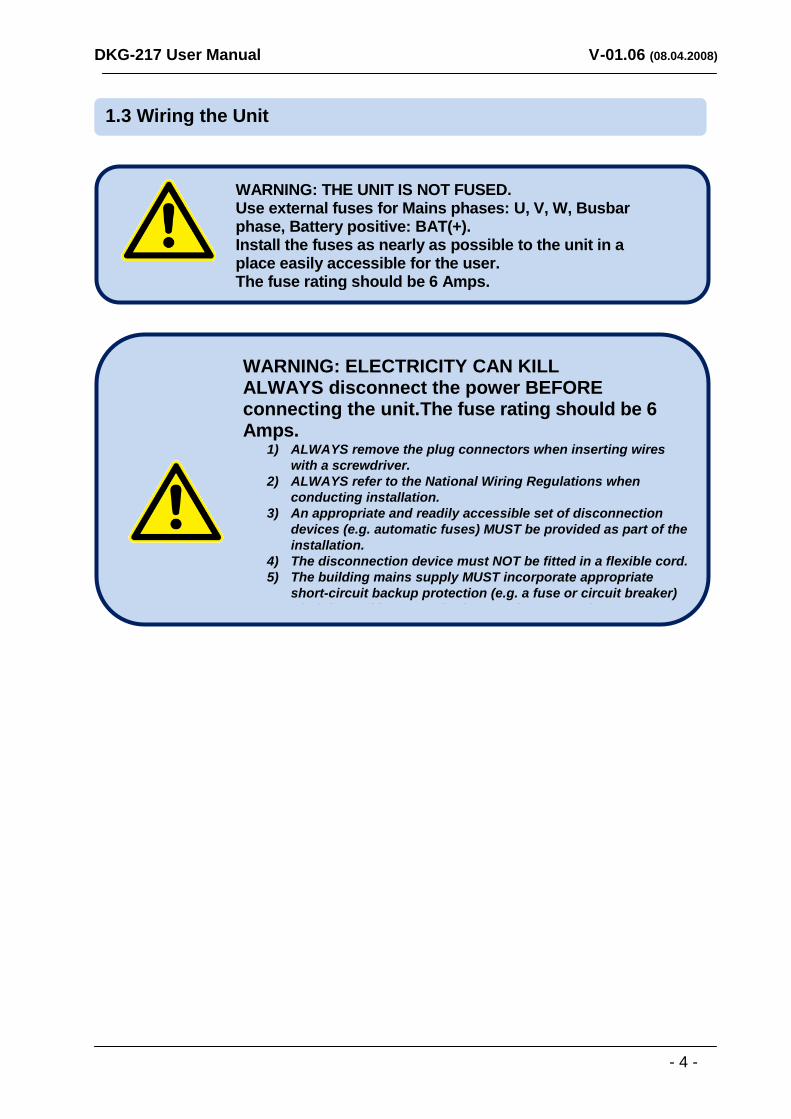
WARNING: ELECTRICITY CAN KILL ALWAYS disconnect the power BEFORE connecting the unit.The fuse rating should be 6 Amps.
1) ALWAYS remove the plug connectors when inserting wires
with a screwdriver.
2) ALWAYS refer to the National Wiring Regulations when
conducting installation.
3) An appropriate and readily accessible set of disconnection
devices (e.g. automatic fuses) MUST be provided as part of the
installation.
4) The disconnection device must NOT be fitted in a flexible cord.
5) The building mains supply MUST incorporate appropriate
short-circuit backup protection (e.g. a fuse or circuit breaker)
of High Breaking Capacity (HBC, at least 1500A).
Use cables of adequate current carrying capacity (at least
0.75mm2) and temperature range.
WARNING: THE UNIT IS NOT FUSED. Use external fuses for Mains phases: U, V, W, Busbar phase, Battery positive: BAT(+). Install the fuses as nearly as possible to the unit in a place easily accessible for the user. The fuse rating should be 6 Amps.
1.3 Wiring the Unit
DKG-217 User Manual V-01.06 (08.04.2008)
- 5 -
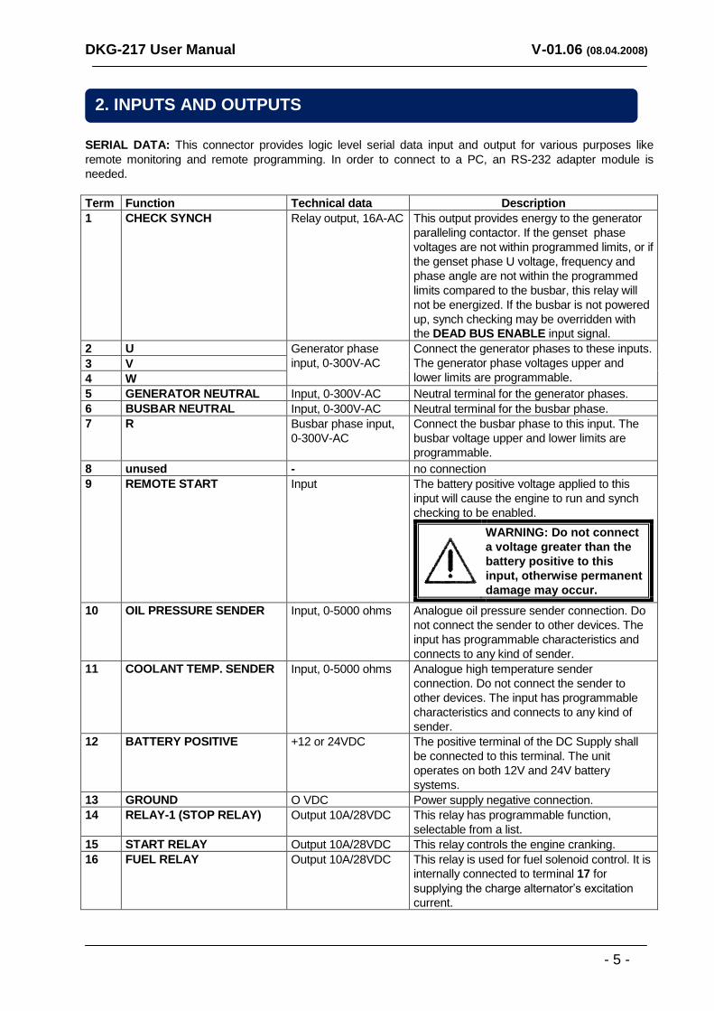
SERIAL DATA: This connector provides logic level serial data input and output for various purposes like
remote monitoring and remote programming. In order to connect to a PC, an RS-232 adapter module is
needed.
Term Function Technical data Description
1 CHECK SYNCH Relay output, 16A-AC This output provides energy to the generator
paralleling contactor. If the genset phase
voltages are not within programmed limits, or if
the genset phase U voltage, frequency and
phase angle are not within the programmed
limits compared to the busbar, this relay will
not be energized. If the busbar is not powered
up, synch checking may be overridden with
the DEAD BUS ENABLE input signal.
2 U Generator phase
input, 0-300V-AC
Connect the generator phases to these inputs.
The generator phase voltages upper and
lower limits are programmable. 3 V
4 W
5 GENERATOR NEUTRAL Input, 0-300V-AC Neutral terminal for the generator phases.
6 BUSBAR NEUTRAL Input, 0-300V-AC Neutral terminal for the busbar phase.
7 R Busbar phase input,
0-300V-AC
Connect the busbar phase to this input. The
busbar voltage upper and lower limits are
programmable.
8 unused - no connection
9 REMOTE START Input The battery positive voltage applied to this
input will cause the engine to run and synch
checking to be enabled.
WARNING: Do not connect
a voltage greater than the
battery positive to this
input, otherwise permanent
damage may occur.
10 OIL PRESSURE SENDER Input, 0-5000 ohms Analogue oil pressure sender connection. Do
not connect the sender to other devices. The
input has programmable characteristics and
connects to any kind of sender.
11 COOLANT TEMP. SENDER Input, 0-5000 ohms Analogue high temperature sender
connection. Do not connect the sender to
other devices. The input has programmable
characteristics and connects to any kind of
sender.
12 BATTERY POSITIVE +12 or 24VDC The positive terminal of the DC Supply shall
be connected to this terminal. The unit
operates on both 12V and 24V battery
systems.
13 GROUND O VDC Power supply negative connection.
14 RELAY-1 (STOP RELAY) Output 10A/28VDC This relay has programmable function,
selectable from a list.
15 START RELAY Output 10A/28VDC This relay controls the engine cranking.
16 FUEL RELAY Output 10A/28VDC This relay is used for fuel solenoid control. It is
internally connected to terminal 17 for
supplying the charge alternator‟s excitation
current.
2. INPUTS AND OUTPUTS
DKG-217 User Manual V-01.06 (08.04.2008)
- 6 -
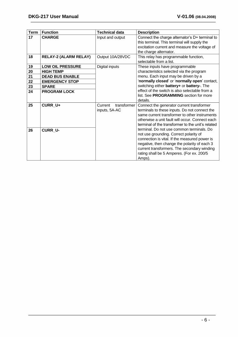
Term Function Technical data Description
17 CHARGE Input and output Connect the charge alternator‟s D+ terminal to
this terminal. This terminal will supply the
excitation current and measure the voltage of
the charge alternator.
18 RELAY-2 (ALARM RELAY) Output 10A/28VDC This relay has programmable function,
selectable from a list.
19 LOW OIL PRESSURE Digital inputs These inputs have programmable
characteristics selected via the program
menu. Each input may be driven by a
„normally closed‟ or „normally open‟ contact,
switching either battery+ or battery-. The
effect of the switch is also selectable from a
list. See PROGRAMMING section for more
details.
20 HIGH TEMP
21 DEAD BUS ENABLE
22 EMERGENCY STOP
23 SPARE
24 PROGRAM LOCK
25 CURR_U+ Current transformer
inputs, 5A-AC
Connect the generator current transformer
terminals to these inputs. Do not connect the
same current transformer to other instruments
otherwise a unit fault will occur. Connect each
terminal of the transformer to the unit‟s related
terminal. Do not use common terminals. Do
not use grounding. Correct polarity of
connection is vital. If the measured power is
negative, then change the polarity of each 3
current transformers. The secondary winding
rating shall be 5 Amperes. (For ex. 200/5
Amps).
26 CURR_U-
DKG-217 User Manual V-01.06 (08.04.2008)
- 7 -
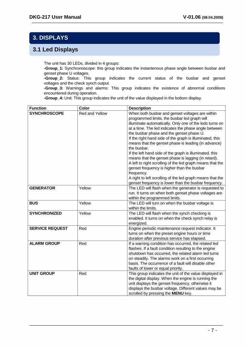
The unit has 30 LEDs, divided in 4 groups:
-Group_1: Synchronoscope: this group indicates the instantenous phase angle between busbar and
genset phase U voltages.
-Group_2: Status: This group indicates the current status of the busbar and genset
voltages and the check synch output.
-Group_3: Warnings and alarms: This group indicates the existence of abnormal conditions
encountered during operation.
-Group_4: Unit: This group indicates the unit of the value displayed in the bottom display.
Function Color Description
SYNCHROSCOPE Red and Yellow When both busbar and genset voltages are within
programmed limits, the busbar led graph will
illuminate automatically. Only one of the leds turns on
at a time. The led indicates the phase angle between
the busbar phase and the genset phase U.
If the right hand side of the graph is illuminated, this
means that the genset phase is leading (in advance)
the busbar.
If the left hand side of the graph is illuminated, this
means that the genset phase is lagging (in retard).
A left to right scrolling of the led graph means that the
genset frequency is higher than the busbar
frequency.
A right to left scrolling of the led graph means that the
genset frequency is lower than the busbar frequency.
GENERATOR Yellow The LED will flash when the generator is requested to
run. It turns on when both genset phase voltages are
within the programmed limits.
BUS Yellow The LED will turn on when the busbar voltage is
within the limits.
SYNCHRONIZED Yellow The LED will flash when the synch checking is
enabled. It turns on when the check synch relay is
energized.
SERVICE REQUEST Red Engine periodic maintenance request indicator. It
turns on when the preset engine hours or time
duration after previous service has elapsed.
ALARM GROUP Red If a warning condition has occurred, the related led
flashes. If a fault condition resulting to the engine
shutdown has occurred, the related alarm led turns
on steadily. The alarms work on a first occurring
basis. The occurrence of a fault will disable other
faults of lower or equal priority.
UNIT GROUP Red This group indicates the unit of the value displayed in
the digital display. When the engine is running the
unit displays the genset frequency, otherwise it
displays the busbar voltage. Different values may be
scrolled by pressing the MENU key.
3.1 Led Displays
3. DISPLAYS
DKG-217 User Manual V-01.06 (08.04.2008)
- 8 -
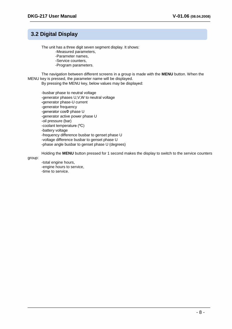
The unit has a three digit seven segment display. It shows: -Measured parameters, -Parameter names, -Service counters, -Program parameters.
The navigation between different screens in a group is made with the MENU button. When the MENU key is pressed, the parameter name will be displayed.
By pressing the MENU key, below values may be displayed:
-busbar phase to neutral voltage
-generator phases U,V,W to neutral voltage
-generator phase-U current
-generator frequency
-generator cosΦ phase U
-generator active power phase U
-oil pressure (bar)
-coolant temperature (ºC)
-battery voltage
-frequency difference busbar to genset phase U
-voltage difference busbar to genset phase U
-phase angle busbar to genset phase U (degrees) Holding the MENU button pressed for 1 second makes the display to switch to the service counters group: -total engine hours, -engine hours to service, -time to service.
3.2 Digital Display
DKG-217 User Manual V-01.06 (08.04.2008)
- 9 -
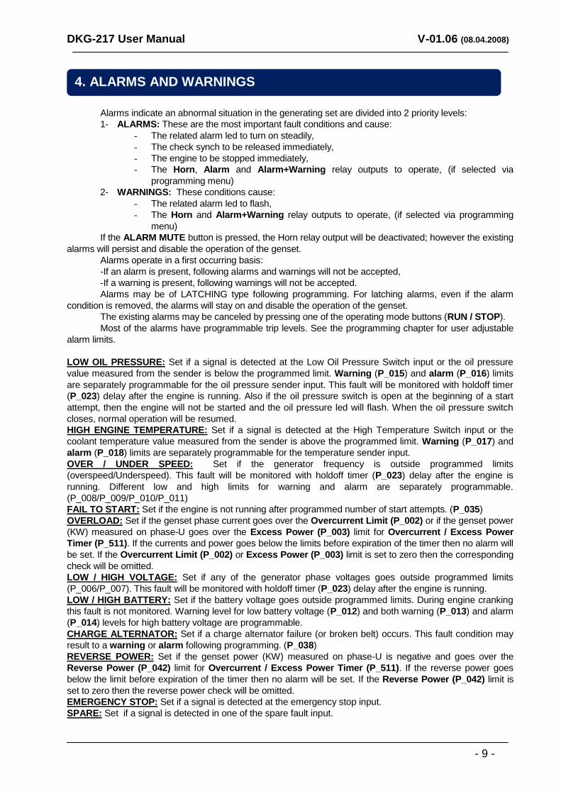
Alarms indicate an abnormal situation in the generating set are divided into 2 priority levels:
1- ALARMS: These are the most important fault conditions and cause:
- The related alarm led to turn on steadily,
- The check synch to be released immediately,
- The engine to be stopped immediately,
- The Horn, Alarm and Alarm+Warning relay outputs to operate, (if selected via
programming menu)
2- WARNINGS: These conditions cause:
- The related alarm led to flash,
- The Horn and Alarm+Warning relay outputs to operate, (if selected via programming
menu)
If the ALARM MUTE button is pressed, the Horn relay output will be deactivated; however the existing
alarms will persist and disable the operation of the genset.
Alarms operate in a first occurring basis:
-If an alarm is present, following alarms and warnings will not be accepted,
-If a warning is present, following warnings will not be accepted.
Alarms may be of LATCHING type following programming. For latching alarms, even if the alarm
condition is removed, the alarms will stay on and disable the operation of the genset.
The existing alarms may be canceled by pressing one of the operating mode buttons (RUN / STOP).
Most of the alarms have programmable trip levels. See the programming chapter for user adjustable
alarm limits.
LOW OIL PRESSURE: Set if a signal is detected at the Low Oil Pressure Switch input or the oil pressure
value measured from the sender is below the programmed limit. Warning (P_015) and alarm (P_016) limits
are separately programmable for the oil pressure sender input. This fault will be monitored with holdoff timer
(P_023) delay after the engine is running. Also if the oil pressure switch is open at the beginning of a start
attempt, then the engine will not be started and the oil pressure led will flash. When the oil pressure switch
closes, normal operation will be resumed.
HIGH ENGINE TEMPERATURE: Set if a signal is detected at the High Temperature Switch input or the
coolant temperature value measured from the sender is above the programmed limit. Warning (P_017) and
alarm (P_018) limits are separately programmable for the temperature sender input.
OVER / UNDER SPEED: Set if the generator frequency is outside programmed limits
(overspeed/Underspeed). This fault will be monitored with holdoff timer (P_023) delay after the engine is
running. Different low and high limits for warning and alarm are separately programmable.
(P_008/P_009/P_010/P_011)
FAIL TO START: Set if the engine is not running after programmed number of start attempts. (P_035)
OVERLOAD: Set if the genset phase current goes over the Overcurrent Limit (P_002) or if the genset power
(KW) measured on phase-U goes over the Excess Power (P_003) limit for Overcurrent / Excess Power
Timer (P_511). If the currents and power goes below the limits before expiration of the timer then no alarm will
be set. If the Overcurrent Limit (P_002) or Excess Power (P_003) limit is set to zero then the corresponding
check will be omitted.
LOW / HIGH VOLTAGE: Set if any of the generator phase voltages goes outside programmed limits
(P_006/P_007). This fault will be monitored with holdoff timer (P_023) delay after the engine is running.
LOW / HIGH BATTERY: Set if the battery voltage goes outside programmed limits. During engine cranking
this fault is not monitored. Warning level for low battery voltage (P_012) and both warning (P_013) and alarm
(P_014) levels for high battery voltage are programmable.
CHARGE ALTERNATOR: Set if a charge alternator failure (or broken belt) occurs. This fault condition may
result to a warning or alarm following programming. (P_038)
REVERSE POWER: Set if the genset power (KW) measured on phase-U is negative and goes over the
Reverse Power (P_042) limit for Overcurrent / Excess Power Timer (P_511). If the reverse power goes
below the limit before expiration of the timer then no alarm will be set. If the Reverse Power (P_042) limit is
set to zero then the reverse power check will be omitted.
EMERGENCY STOP: Set if a signal is detected at the emergency stop input.
SPARE: Set if a signal is detected in one of the spare fault input.
4. ALARMS AND WARNINGS
DKG-217 User Manual V-01.06 (08.04.2008)
- 10 -
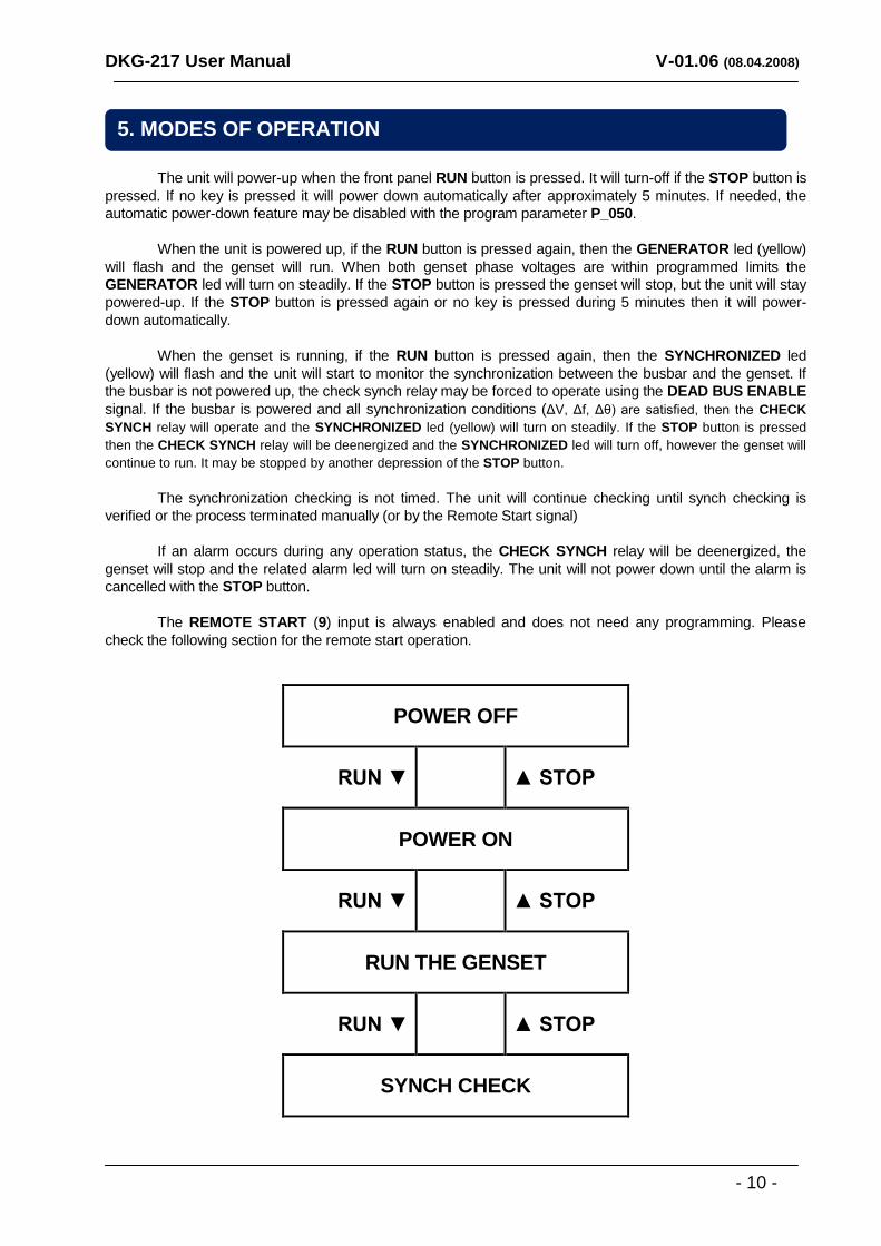
The unit will power-up when the front panel RUN button is pressed. It will turn-off if the STOP button is
pressed. If no key is pressed it will power down automatically after approximately 5 minutes. If needed, the
automatic power-down feature may be disabled with the program parameter P_050.
When the unit is powered up, if the RUN button is pressed again, then the GENERATOR led (yellow)
will flash and the genset will run. When both genset phase voltages are within programmed limits the
GENERATOR led will turn on steadily. If the STOP button is pressed the genset will stop, but the unit will stay
powered-up. If the STOP button is pressed again or no key is pressed during 5 minutes then it will power-
down automatically.
When the genset is running, if the RUN button is pressed again, then the SYNCHRONIZED led
(yellow) will flash and the unit will start to monitor the synchronization between the busbar and the genset. If
the busbar is not powered up, the check synch relay may be forced to operate using the DEAD BUS ENABLE
signal. If the busbar is powered and all synchronization conditions (ΔV, Δf, Δθ) are satisfied, then the CHECK
SYNCH relay will operate and the SYNCHRONIZED led (yellow) will turn on steadily. If the STOP button is pressed
then the CHECK SYNCH relay will be deenergized and the SYNCHRONIZED led will turn off, however the genset will
continue to run. It may be stopped by another depression of the STOP button.
The synchronization checking is not timed. The unit will continue checking until synch checking is
verified or the process terminated manually (or by the Remote Start signal)
If an alarm occurs during any operation status, the CHECK SYNCH relay will be deenergized, the
genset will stop and the related alarm led will turn on steadily. The unit will not power down until the alarm is
cancelled with the STOP button.
The REMOTE START (9) input is always enabled and does not need any programming. Please
check the following section for the remote start operation.
POWER OFF
RUN ▼ ▲ STOP
POWER ON
RUN ▼ ▲ STOP
RUN THE GENSET
RUN ▼ ▲ STOP
SYNCH CHECK
5. MODES OF OPERATION
DKG-217 User Manual V-01.06 (08.04.2008)
- 11 -
The unit offers the possibility of REMOTE START mode of operation. The REMOTE START (9) input is always enabled and does not need any programming. The Remote Start signal should be connected to the REMOTE START (9) input. The REMOTE START signal is always the battery positive voltage. Due to the zero power at rest structure, power should be supplied to this input in order to wake-up the unit.
The REMOTE START signal is equivalent to 3 successive depressions of the RUN button. This means that, upon arrival of the REMOTE START signal the unit: -will power up -will run the engine -will check the synchronization and operate the CHECK SYNCH relay. If the unit is to close on an unpowered bus, this can be enabled with the DEAD BUS ENABLE signal. However even if the dead bus closing is enabled to a bus which is powered up, the unit will not close and will check the synchronization.
The unit will check the synchronization when both genset and bus phase voltages are within
programmed limits and the SYNCHRONIZED led is flashing.
If both busbar and genset phase voltages are within programmed limits, then the synchroscope led
bargraph will illuminate. The bargraph will show the phase angle between busbar and genset phase U.
The synchronization checking consists of the verification of below conditions during 4 consecutive
busbar cycles:
-the busbar voltage should be between limits set by P_004 and P_005
-both genset phase voltages should be between limits set by P_006 and P_007
-the frequency difference between the busbar and genset phase U should not exceed the limit set by P_039
-the voltage difference between the busbar and genset phase U should not exceed the limit set by P_040
-the phase angle between the busbar and genset phase U should not exceed the limit set by P_041
If all above conditions are satisfied for 4 consecutive busbar cycles then the CHECK SYNCH relay will
be immediately energized.
If above conditions are denied for 8 consecutive busbar cycles then the CHECK SYNCH relay will be
immediately deenergized.
It is the responsibility of the panel builder to use a quickly closing contactor.
6.2 Synchronization Checking
Do not connect a voltage greater than the battery positive to this input, otherwise permanent damage to the unit may occur.
6.1 Remote Start Operation
6. OTHER FEATURES
DKG-217 User Manual V-01.06 (08.04.2008)
- 12 -
The unit has the ability to adapt to any type of oil pressure and temperature senders. The commonly used standard sender characteristics are recorded in memory and selectable from a list. However non standard senders may also be used by entering their characteristics to the table. Oil Pressure Sender Type Selection: The oil pressure sender is selected using parameter P_019. The selectable sender types are: 0: The sender characteristics are defined in table using parameters P_131 to P_142. 1: VDO 0-7 bars (10-180 ohms) 2: VDO 0-10 bars (280-20 ohms) 3: DATCON 0-7 bars (240-33 ohms) 4: DATCON 0-10 bars (240-33 ohms) 5: DATCON 0-7 bars (0-90 ohms) 6: DATCON 0-10 bars (0-90 ohms) 7: DATCON 0-7 bars (75-10 ohms) Temperature Sender Selection: The temperature sender is selected using parameter P_020. The selectable sender types are: 0: The sender characteristics are defined in table using parameters P_143 to P_154. 1: VDO 2: DATCON DAH type 3: DATCON DAL type
Especially on engines without a body heater, or with a failing one, it may be desired that the genset should not take the load before reaching a suitable temperature. The unit offers 2 different ways of engine heating. 1. Timer controlled heating: This operation mode is selected when the parameter P_037 is set to 0. In this mode, the engine will run during parameter P_029, and then the synchronization checking will be enabled. 2. Timer and temperature controlled heating: This operation mode is selected when the parameter P_037 is set to 1. In this mode, at first the engine will run during parameter P_029, then it will continue to run until the measured coolant temperature reaches the limit defined in parameter P_022. When the requested temperature is reached, the synchronization checking will be enabled. This operation mode may be used as a backup to the engine body heater. If the engine body is warm the heating will be skipped.
6.4 Engine Heating Operation
6.3 Sender type Selection
DKG-217 User Manual V-01.06 (08.04.2008)
- 13 -
This led is designed to help the periodic maintenance of the genset to be made consistently.
The periodic maintenance is basically carried out after a given engine hours (for example 200 hours),
but even if this amount of engine hours is not fulfilled, it is performed after a given time limit (for example 12
months).
The unit has both programmable engine hours and maintenance time limit. The engine hours is
programmable with 50-hour steps (P_044), the time limit is programmable between with 1 month steps
(P_045). If any of the programmed values is zero, this means that the parameter will not be used. For example
a maintenance period of 0 months indicates that the unit will request maintenance only based on engine
hours, there will be no time limit. If the engine hours is also selected as 0 hours this will mean that the
SERVICE REQUEST display will be inoperative.
When the engine hours OR the time limit is over, the SERVICE REQUEST led (red) will start to flash.
To turn off the led, and reset the service period, press together the ALARM MUTE and LAMP
TEST keys for 5 seconds. The display will show “SER”.
The remaining engine hours and the remaining time limit are kept stored in a non-volatile memory and
are not affected by power supply failures.
The remaining time and engine hours to service may be checked via the statistics menu selected by
pressing the MENU key for 1 second.
When the MENU key is pressed the display will show “HtS” (hours to service). When the MENU key is
released it will show the first 3 digits of the engine hours to service. When the MENU key is pressed again, the
display will show “HtS” (hours to service). When the MENU key is released it will show the last 3 digits of the
engine hours to service.
When the MENU key is pressed the display will show “ttS” (time to service). When the MENU key is
released it will show the first 3 digits of the remaining days to service. When the MENU key is pressed again,
the display will show “ttS” (time to service). When the MENU key is released it will show the last 3 digits of the
remaining days to service.
The unit features a non-erasable incremental engine hour meter. The hour meter information is kept in
a non-volatile memory and is not affected by power supply failures.
The engine hours may be displayed via the statistics menu selected by pressing the MENU key for 1
second.
When the MENU key is pressed the display will show “EnH” (engine hours). When the MENU key is
released it will show the first 3 digits of the engine hours. When the MENU key is pressed again, the display
will show “EnH” (engine hours). When the MENU key is released it will show the last 3 digits of the engine
hours.
6.6 Engine Hour Meter
The SERVICE REQUEST led has no effect on the genset operation.
6.5 Service Request Display
DKG-217 User Manual V-01.06 (08.04.2008)
- 14 -
The unit offers the remote monitoring and programming features over the telephone network via a modem connection. The program used for remote monitoring and programming is the same as the program used for RS-232 connection. If the modem is connected, the program parameter P_043 should be set to 1, otherwise faulty operation may occur. For PCs without a serial port, below USB to serial adapters are tested and approved : DIGITUS USB 2.0 TO RS-232 ADAPTER (PRODUCT CODE: DA70146 REV 1.1) DIGITUS USB 1.1 TO RS-232 ADAPTER (PRODUCT CODE: DA70145 REV 1.1) FLEXY USB 1.1 TO SERIAL ADAPTER (PRODUCT CODE BF-810) CASECOM USB TO SERIAL CONVERTER (MODEL: RS-01)
Thanks to its standard serial port, the unit offers the remote monitoring and programming feature.
The serial port has logic level outputs and is connected to the PC or modem with a RS-232
adapter.
The remote monitoring and programming PC software may be downloaded from
www.datakom.com.tr internet site.
The software allows the visualization and recording of all measured parameters. The recorded
parameters may then be analyzed graphically and printed. The software also allows the programming of
the unit and the storage of the program parameters to PC or the downloading of stored parameters from
PC to the unit.
The unit provides a set of non resettable incremental counters for statistical purposes. The counters consist on: -total engine cranks, -total genset runs, -total genset on load. These counters are kept in a non-volatile memory and are not affected from power failures. The statistical counters are only displayed on the PC screen using the remote monitoring and programming software. They can not be displayed on the unit.
Wipe the unit, if necessary with a soft damp cloth. Do not use chemical agents.
DO NOT OPEN THE UNIT !
There are NO serviceable parts inside the unit.
8. MAINTENANCE
7. STATISTICAL COUNTERS
6.8 Remote Monitoring and Programming
6.7 Modem Connection
DKG-217 User Manual V-01.06 (08.04.2008)
- 15 -
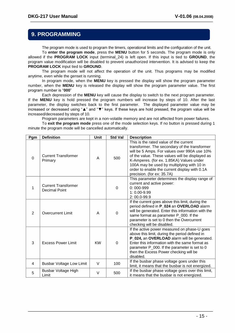
The program mode is used to program the timers, operational limits and the configuration of the unit.
To enter the program mode, press the MENU button for 5 seconds. The program mode is only
allowed if the PROGRAM LOCK input (terminal_24) is left open. If this input is tied to GROUND, the
program value modification will be disabled to prevent unauthorized intervention. It is advised to keep the
PROGRAM LOCK input tied to GROUND.
The program mode will not affect the operation of the unit. Thus programs may be modified
anytime, even while the genset is running.
In program mode, when the MENU key is pressed the display will show the program parameter
number, when the MENU key is released the display will show the program parameter value. The first
program number is “000”
Each depression of the MENU key will cause the display to switch to the next program parameter.
If the MENU key is hold pressed the program numbers will increase by steps of 10. After the last
parameter, the display switches back to the first parameter. The displayed parameter value may be
increased or decreased using “▲” and “▼” keys. If these keys are hold pressed, the program value will be
increased/decreased by steps of 10. Program parameters are kept in a non-volatile memory and are not affected from power failures.
To exit the program mode press one of the mode selection keys. If no button is pressed during 1
minute the program mode will be cancelled automatically.
Pgm Definition Unit Std Val Description
0 Current Transformer Primary
A 500
This is the rated value of the current transformer. The secondary of the transformer will be 5 Amps. For values over 990A use 10% of the value. These values will be displayed as K-Amperes. (for ex. 1.85KA) Values under 100A may be used by multiplying with 10 in order to enable the current display with 0.1A precision. (for ex: 35.7A)
1 Current Transformer Decimal Point
0
This parameter determines the display range of current and active power: 0: 000-999 1: 0.00-9.99 2: 00.0-99.9
2 Overcurrent Limit A 0
If the current goes above this limit, during the period defined in P_024 an OVERLOAD alarm will be generated. Enter this information with the same format as parameter P_000. If the parameter is set to 0 then the Overcurrent checking will be disabled.
3 Excess Power Limit KW 0
If the active power measured on phase-U goes above this limit, during the period defined in P_024, an OVERLOAD alarm will be generated. Enter this information with the same format as parameter P_000. If the parameter is set to 0 then the Excess Power checking will be disabled.
4 Busbar Voltage Low Limit V 100 If the busbar phase voltage goes under this limit, it means that the busbar is not energized.
5 Busbar Voltage High Limit
V 500 If the busbar phase voltage goes over this limit, it means that the busbar is not energized.
9. PROGRAMMING
DKG-217 User Manual V-01.06 (08.04.2008)
- 16 -
Pgm Definition Unit Std Val Description
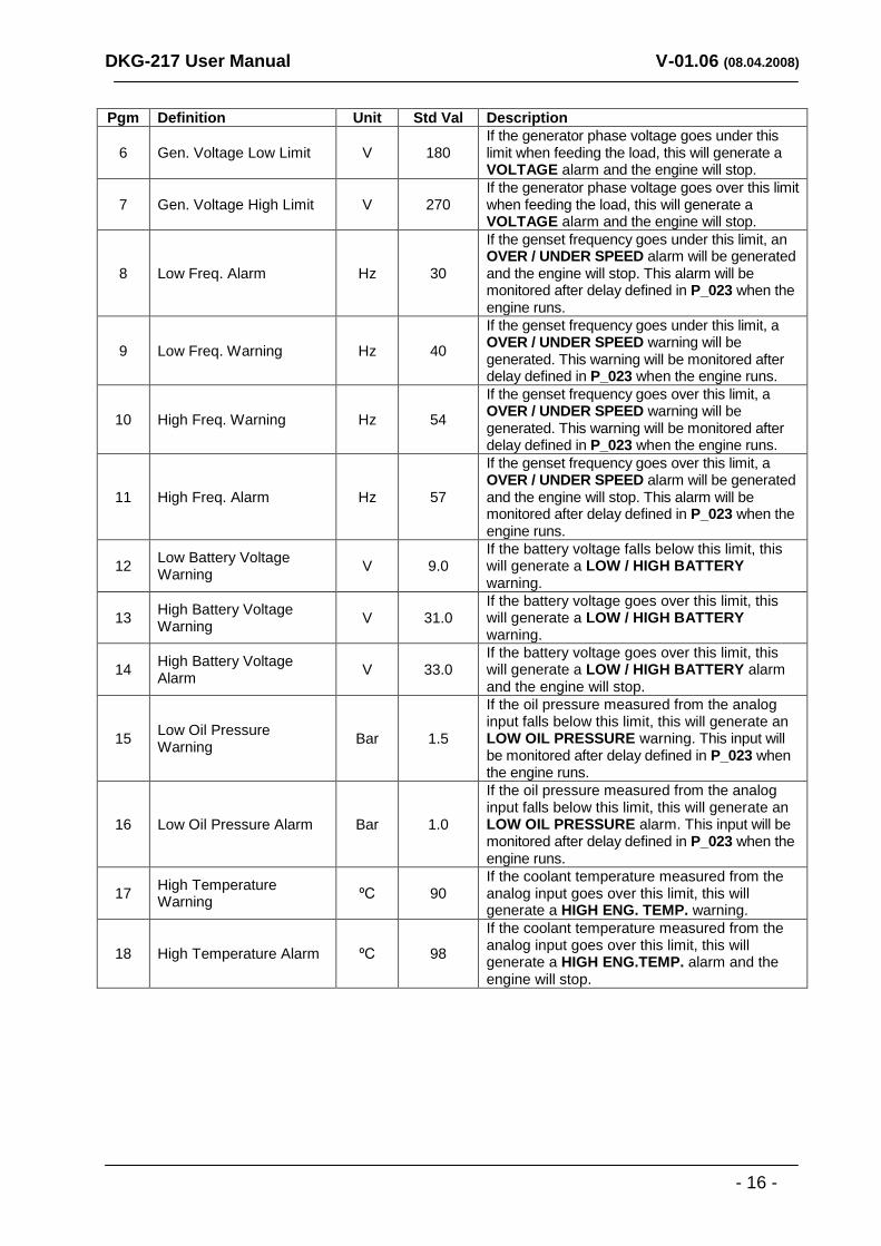
6 Gen. Voltage Low Limit V 180 If the generator phase voltage goes under this limit when feeding the load, this will generate a VOLTAGE alarm and the engine will stop.
7 Gen. Voltage High Limit V 270 If the generator phase voltage goes over this limit when feeding the load, this will generate a VOLTAGE alarm and the engine will stop.
8 Low Freq. Alarm Hz 30
If the genset frequency goes under this limit, an OVER / UNDER SPEED alarm will be generated and the engine will stop. This alarm will be monitored after delay defined in P_023 when the engine runs.
9 Low Freq. Warning Hz 40
If the genset frequency goes under this limit, a OVER / UNDER SPEED warning will be generated. This warning will be monitored after delay defined in P_023 when the engine runs.
10 High Freq. Warning Hz 54
If the genset frequency goes over this limit, a OVER / UNDER SPEED warning will be generated. This warning will be monitored after delay defined in P_023 when the engine runs.
11 High Freq. Alarm Hz 57
If the genset frequency goes over this limit, a OVER / UNDER SPEED alarm will be generated and the engine will stop. This alarm will be monitored after delay defined in P_023 when the engine runs.
12 Low Battery Voltage Warning
V 9.0 If the battery voltage falls below this limit, this will generate a LOW / HIGH BATTERY warning.
13 High Battery Voltage Warning
V 31.0 If the battery voltage goes over this limit, this will generate a LOW / HIGH BATTERY warning.
14 High Battery Voltage Alarm
V 33.0 If the battery voltage goes over this limit, this will generate a LOW / HIGH BATTERY alarm and the engine will stop.
15 Low Oil Pressure Warning
Bar 1.5
If the oil pressure measured from the analog input falls below this limit, this will generate an LOW OIL PRESSURE warning. This input will be monitored after delay defined in P_023 when the engine runs.
16 Low Oil Pressure Alarm Bar 1.0
If the oil pressure measured from the analog input falls below this limit, this will generate an LOW OIL PRESSURE alarm. This input will be monitored after delay defined in P_023 when the engine runs.
17 High Temperature Warning
ºC 90 If the coolant temperature measured from the analog input goes over this limit, this will generate a HIGH ENG. TEMP. warning.
18 High Temperature Alarm ºC 98
If the coolant temperature measured from the analog input goes over this limit, this will generate a HIGH ENG.TEMP. alarm and the engine will stop.
DKG-217 User Manual V-01.06 (08.04.2008)
- 17 -
Pgm Definition Unit Std Val Description
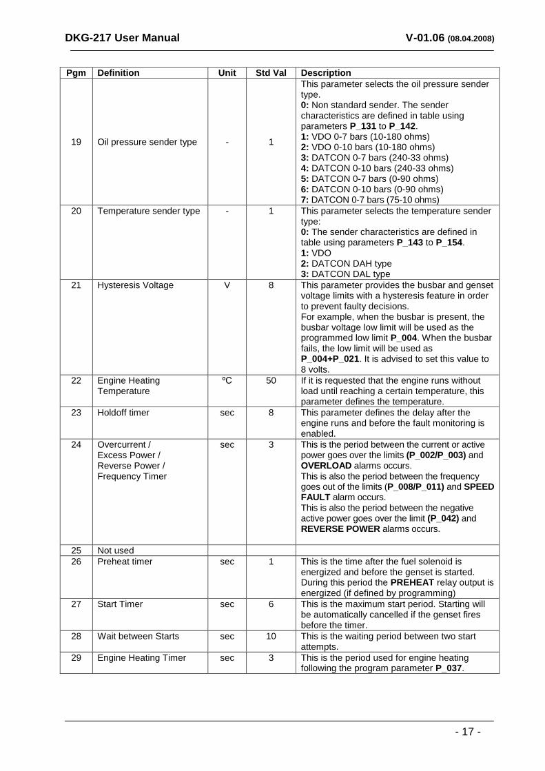
19 Oil pressure sender type - 1
This parameter selects the oil pressure sender type. 0: Non standard sender. The sender characteristics are defined in table using parameters P_131 to P_142. 1: VDO 0-7 bars (10-180 ohms) 2: VDO 0-10 bars (10-180 ohms) 3: DATCON 0-7 bars (240-33 ohms) 4: DATCON 0-10 bars (240-33 ohms) 5: DATCON 0-7 bars (0-90 ohms) 6: DATCON 0-10 bars (0-90 ohms) 7: DATCON 0-7 bars (75-10 ohms)
20 Temperature sender type - 1 This parameter selects the temperature sender type: 0: The sender characteristics are defined in table using parameters P_143 to P_154. 1: VDO 2: DATCON DAH type 3: DATCON DAL type
21 Hysteresis Voltage V 8 This parameter provides the busbar and genset voltage limits with a hysteresis feature in order to prevent faulty decisions. For example, when the busbar is present, the busbar voltage low limit will be used as the programmed low limit P_004. When the busbar fails, the low limit will be used as P_004+P_021. It is advised to set this value to 8 volts.
22 Engine Heating Temperature
ºC 50 If it is requested that the engine runs without load until reaching a certain temperature, this parameter defines the temperature.
23 Holdoff timer sec 8 This parameter defines the delay after the engine runs and before the fault monitoring is enabled.
24 Overcurrent / Excess Power / Reverse Power / Frequency Timer
sec 3 This is the period between the current or active power goes over the limits (P_002/P_003) and OVERLOAD alarms occurs. This is also the period between the frequency goes out of the limits (P_008/P_011) and SPEED FAULT alarm occurs. This is also the period between the negative active power goes over the limit (P_042) and REVERSE POWER alarms occurs.
25 Not used
26 Preheat timer sec 1 This is the time after the fuel solenoid is energized and before the genset is started. During this period the PREHEAT relay output is energized (if defined by programming)
27 Start Timer sec 6 This is the maximum start period. Starting will be automatically cancelled if the genset fires before the timer.
28 Wait between Starts sec 10 This is the waiting period between two start attempts.
29 Engine Heating Timer sec 3 This is the period used for engine heating following the program parameter P_037.
DKG-217 User Manual V-01.06 (08.04.2008)
- 18 -
Pgm Definition Unit Std Val Description
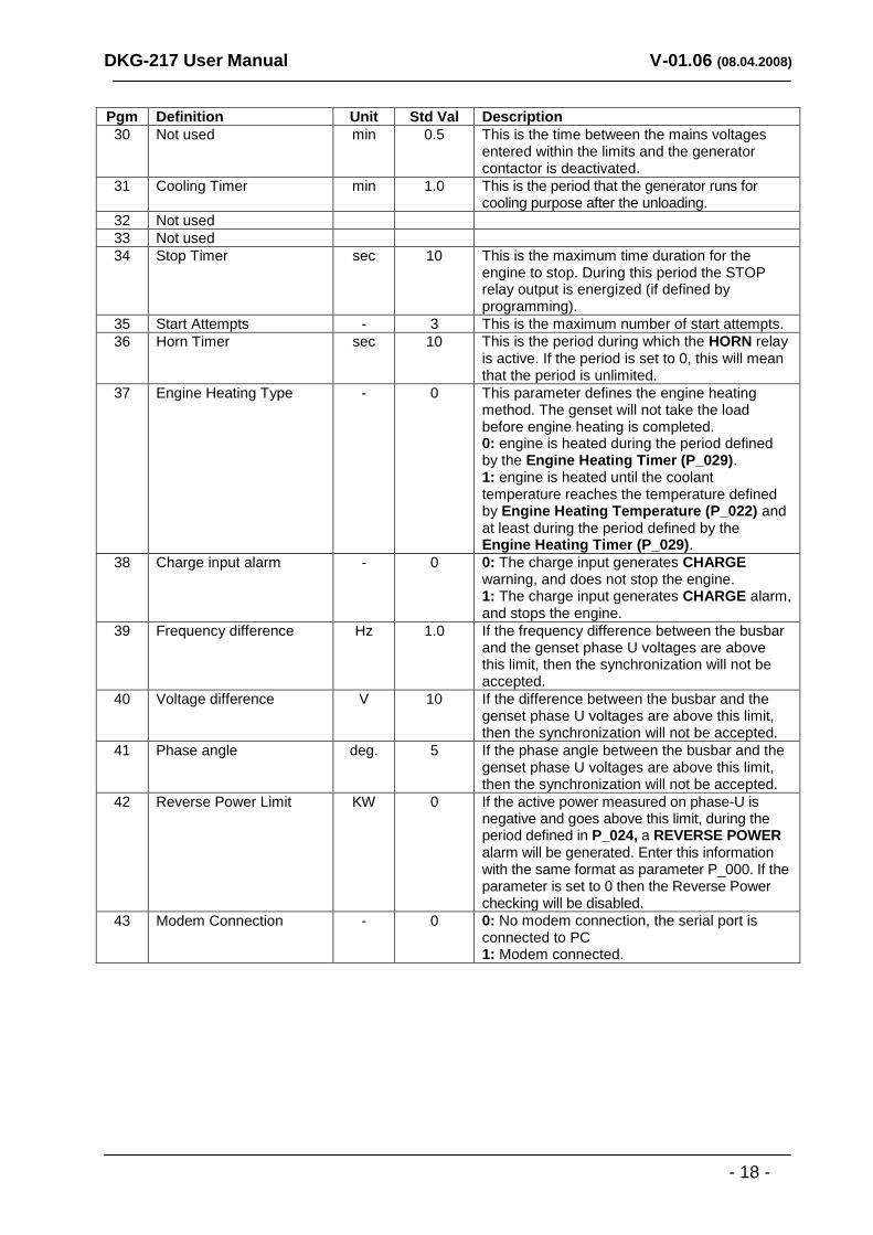
30 Not used min 0.5 This is the time between the mains voltages entered within the limits and the generator contactor is deactivated.
31 Cooling Timer min 1.0 This is the period that the generator runs for cooling purpose after the unloading.
32 Not used
33 Not used
34 Stop Timer sec 10 This is the maximum time duration for the engine to stop. During this period the STOP relay output is energized (if defined by programming).
35 Start Attempts - 3 This is the maximum number of start attempts.
36 Horn Timer sec 10 This is the period during which the HORN relay is active. If the period is set to 0, this will mean that the period is unlimited.
37 Engine Heating Type - 0 This parameter defines the engine heating method. The genset will not take the load before engine heating is completed. 0: engine is heated during the period defined by the Engine Heating Timer (P_029). 1: engine is heated until the coolant temperature reaches the temperature defined by Engine Heating Temperature (P_022) and at least during the period defined by the Engine Heating Timer (P_029).
38 Charge input alarm - 0 0: The charge input generates CHARGE warning, and does not stop the engine. 1: The charge input generates CHARGE alarm, and stops the engine.
39 Frequency difference Hz 1.0 If the frequency difference between the busbar and the genset phase U voltages are above this limit, then the synchronization will not be accepted.
40 Voltage difference V 10 If the difference between the busbar and the genset phase U voltages are above this limit, then the synchronization will not be accepted.
41 Phase angle deg. 5 If the phase angle between the busbar and the genset phase U voltages are above this limit, then the synchronization will not be accepted.
42 Reverse Power Limit KW 0 If the active power measured on phase-U is negative and goes above this limit, during the period defined in P_024, a REVERSE POWER alarm will be generated. Enter this information with the same format as parameter P_000. If the parameter is set to 0 then the Reverse Power checking will be disabled.
43 Modem Connection - 0 0: No modem connection, the serial port is connected to PC 1: Modem connected.
DKG-217 User Manual V-01.06 (08.04.2008)
- 19 -
Pgm Definition Unit Std Val Description
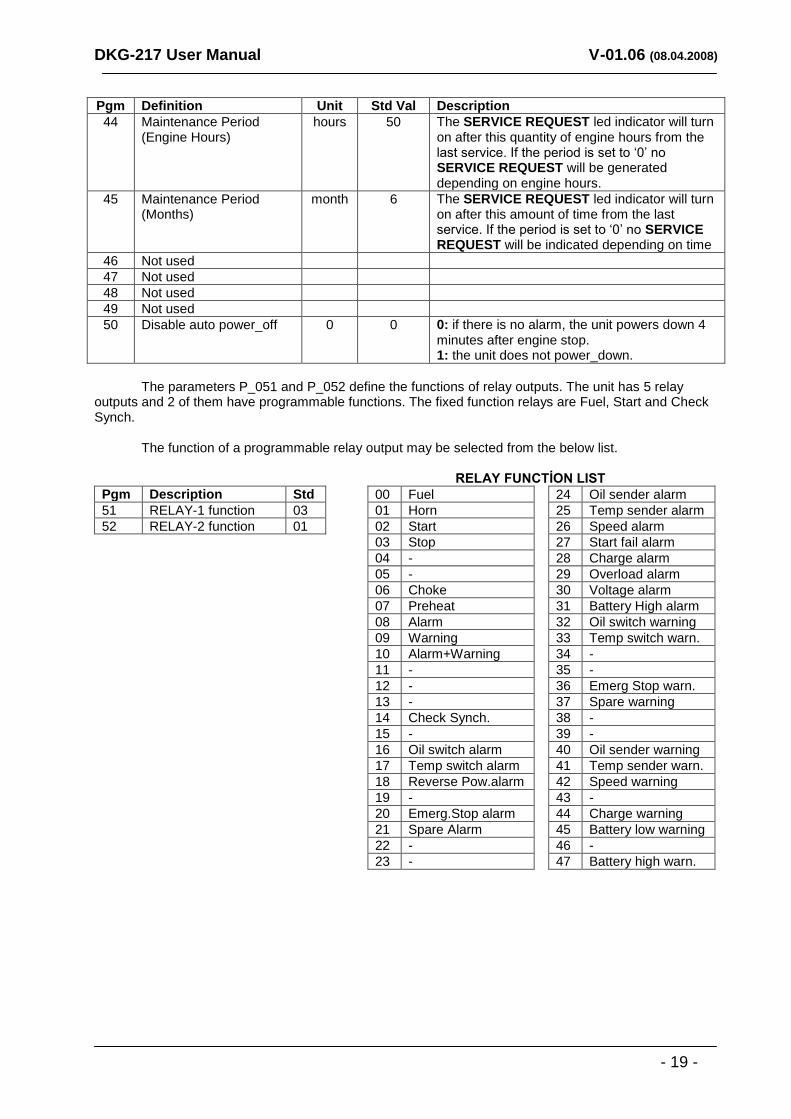
44 Maintenance Period (Engine Hours)
hours 50 The SERVICE REQUEST led indicator will turn on after this quantity of engine hours from the last service. If the period is set to „0‟ no SERVICE REQUEST will be generated depending on engine hours.
45 Maintenance Period (Months)
month 6 The SERVICE REQUEST led indicator will turn on after this amount of time from the last service. If the period is set to „0‟ no SERVICE REQUEST will be indicated depending on time
46 Not used
47 Not used
48 Not used
49 Not used
50 Disable auto power_off 0 0 0: if there is no alarm, the unit powers down 4 minutes after engine stop. 1: the unit does not power_down.
The parameters P_051 and P_052 define the functions of relay outputs. The unit has 5 relay outputs and 2 of them have programmable functions. The fixed function relays are Fuel, Start and Check Synch. The function of a programmable relay output may be selected from the below list. RELAY FUNCTİON LIST
Pgm Description Std
51 RELAY-1 function 03
52 RELAY-2 function 01
00 Fuel
01 Horn
02 Start
03 Stop
04 -
05 -
06 Choke
07 Preheat
08 Alarm
09 Warning
10 Alarm+Warning
11 -
12 -
13 -
14 Check Synch.
15 -
16 Oil switch alarm
17 Temp switch alarm
18 Reverse Pow.alarm
19 -
20 Emerg.Stop alarm
21 Spare Alarm
22 -
23 -
24 Oil sender alarm
25 Temp sender alarm
26 Speed alarm
27 Start fail alarm
28 Charge alarm
29 Overload alarm
30 Voltage alarm
31 Battery High alarm
32 Oil switch warning
33 Temp switch warn.
34 -
35 -
36 Emerg Stop warn.
37 Spare warning
38 -
39 -
40 Oil sender warning
41 Temp sender warn.
42 Speed warning
43 -
44 Charge warning
45 Battery low warning
46 -
47 Battery high warn.
DKG-217 User Manual V-01.06 (08.04.2008)
- 20 -
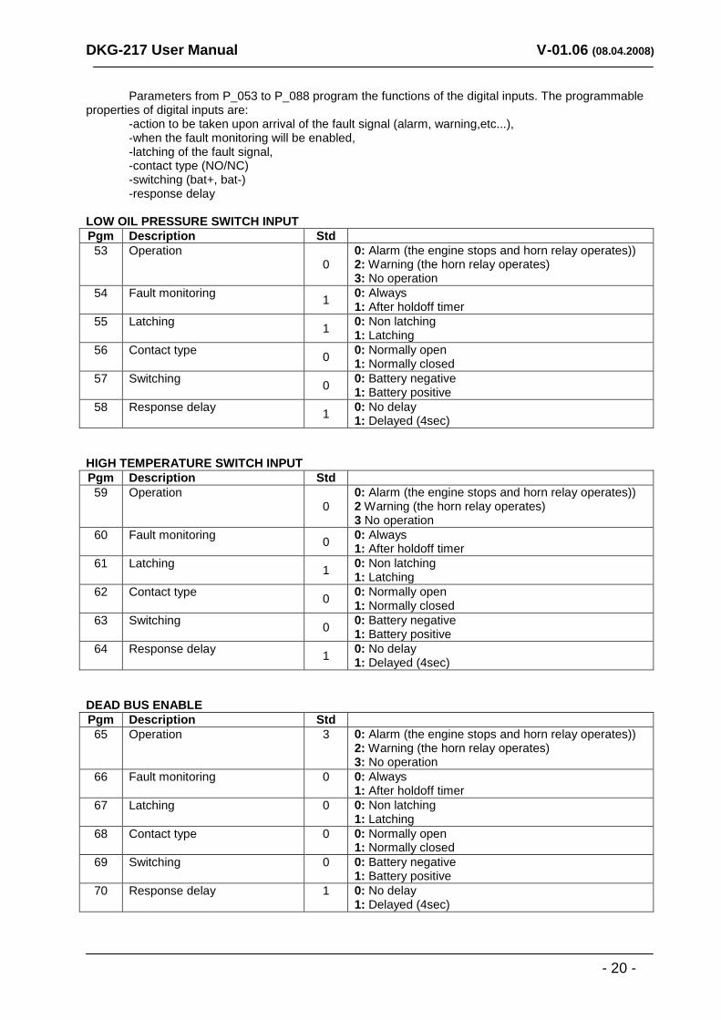
Parameters from P_053 to P_088 program the functions of the digital inputs. The programmable properties of digital inputs are: -action to be taken upon arrival of the fault signal (alarm, warning,etc...), -when the fault monitoring will be enabled, -latching of the fault signal, -contact type (NO/NC) -switching (bat+, bat-) -response delay LOW OIL PRESSURE SWITCH INPUT
Pgm Description Std
53 Operation 0
0: Alarm (the engine stops and horn relay operates)) 2: Warning (the horn relay operates) 3: No operation
54 Fault monitoring 1
0: Always 1: After holdoff timer
55 Latching 1
0: Non latching 1: Latching
56 Contact type 0
0: Normally open 1: Normally closed
57 Switching 0
0: Battery negative 1: Battery positive
58 Response delay 1
0: No delay 1: Delayed (4sec)
HIGH TEMPERATURE SWITCH INPUT
Pgm Description Std
59 Operation 0
0: Alarm (the engine stops and horn relay operates)) 2 Warning (the horn relay operates) 3 No operation
60 Fault monitoring 0
0: Always 1: After holdoff timer
61 Latching 1
0: Non latching 1: Latching
62 Contact type 0
0: Normally open 1: Normally closed
63 Switching 0
0: Battery negative 1: Battery positive
64 Response delay 1
0: No delay 1: Delayed (4sec)
DEAD BUS ENABLE
Pgm Description Std
65 Operation 3 0: Alarm (the engine stops and horn relay operates)) 2: Warning (the horn relay operates) 3: No operation
66 Fault monitoring 0 0: Always 1: After holdoff timer
67 Latching 0 0: Non latching 1: Latching
68 Contact type 0 0: Normally open 1: Normally closed
69 Switching 0 0: Battery negative 1: Battery positive
70 Response delay 1 0: No delay 1: Delayed (4sec)
DKG-217 User Manual V-01.06 (08.04.2008)
- 21 -
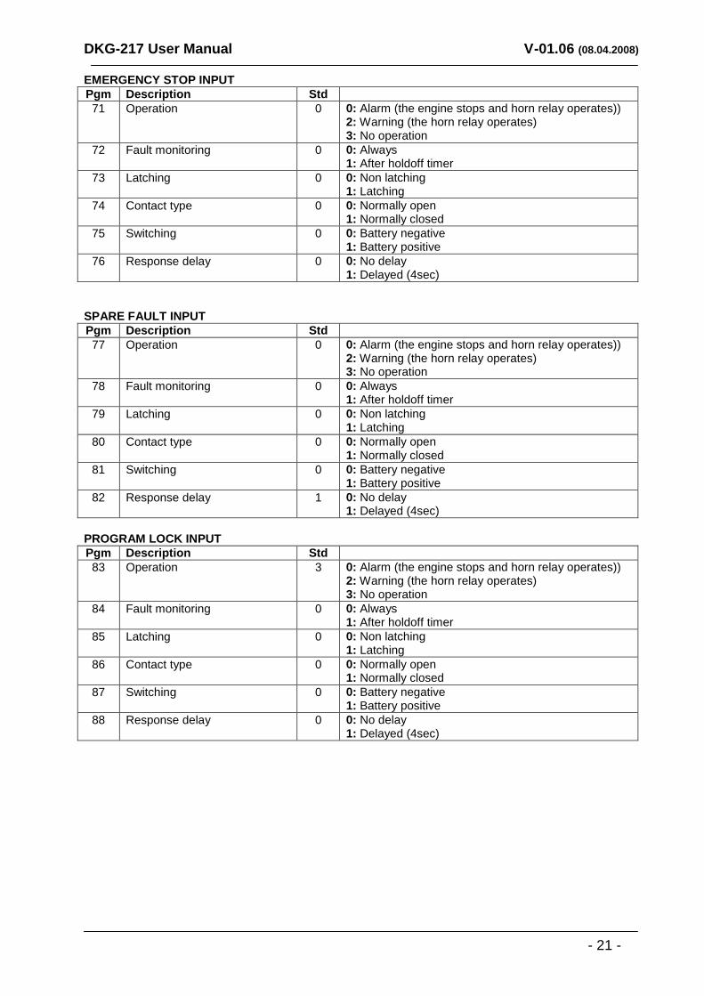
EMERGENCY STOP INPUT
Pgm Description Std
71 Operation 0 0: Alarm (the engine stops and horn relay operates)) 2: Warning (the horn relay operates) 3: No operation
72 Fault monitoring 0 0: Always 1: After holdoff timer
73 Latching 0 0: Non latching 1: Latching
74 Contact type 0 0: Normally open 1: Normally closed
75 Switching 0 0: Battery negative 1: Battery positive
76 Response delay 0 0: No delay 1: Delayed (4sec)
SPARE FAULT INPUT
Pgm Description Std
77 Operation 0 0: Alarm (the engine stops and horn relay operates)) 2: Warning (the horn relay operates) 3: No operation
78 Fault monitoring 0 0: Always 1: After holdoff timer
79 Latching 0 0: Non latching 1: Latching
80 Contact type 0 0: Normally open 1: Normally closed
81 Switching 0 0: Battery negative 1: Battery positive
82 Response delay 1 0: No delay 1: Delayed (4sec)
PROGRAM LOCK INPUT
Pgm Description Std
83 Operation 3 0: Alarm (the engine stops and horn relay operates)) 2: Warning (the horn relay operates) 3: No operation
84 Fault monitoring 0 0: Always 1: After holdoff timer
85 Latching 0 0: Non latching 1: Latching
86 Contact type 0 0: Normally open 1: Normally closed
87 Switching 0 0: Battery negative 1: Battery positive
88 Response delay 0 0: No delay 1: Delayed (4sec)
DKG-217 User Manual V-01.06 (08.04.2008)
- 22 -
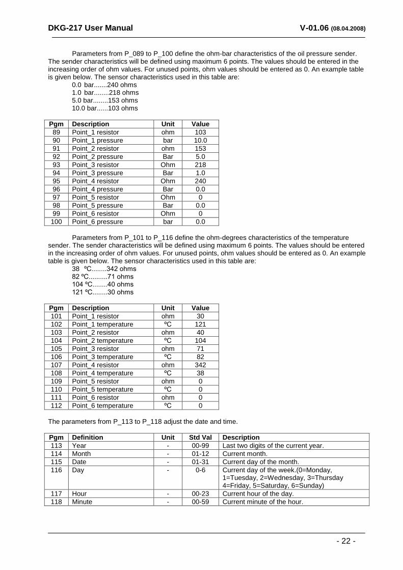
Parameters from P_089 to P_100 define the ohm-bar characteristics of the oil pressure sender. The sender characteristics will be defined using maximum 6 points. The values should be entered in the increasing order of ohm values. For unused points, ohm values should be entered as 0. An example table is given below. The sensor characteristics used in this table are:
0.0 bar.......240 ohms 1.0 bar........218 ohms 5.0 bar........153 ohms 10.0 bar......103 ohms
Pgm Description Unit Value
89 Point_1 resistor ohm 103
90 Point_1 pressure bar 10.0
91 Point_2 resistor ohm 153
92 Point_2 pressure Bar 5.0
93 Point_3 resistor Ohm 218
94 Point_3 pressure Bar 1.0
95 Point_4 resistor Ohm 240
96 Point_4 pressure Bar 0.0
97 Point_5 resistor Ohm 0
98 Point_5 pressure Bar 0.0
99 Point_6 resistor Ohm 0
100 Point_6 pressure bar 0.0
Parameters from P_101 to P_116 define the ohm-degrees characteristics of the temperature sender. The sender characteristics will be defined using maximum 6 points. The values should be entered in the increasing order of ohm values. For unused points, ohm values should be entered as 0. An example table is given below. The sensor characteristics used in this table are:
38 ºC........342 ohms 82 ºC..........71 ohms 104 ºC........40 ohms 121 ºC........30 ohms
Pgm Description Unit Value
101 Point_1 resistor ohm 30
102 Point_1 temperature ºC 121
103 Point_2 resistor ohm 40
104 Point_2 temperature ºC 104
105 Point_3 resistor ohm 71
106 Point_3 temperature ºC 82
107 Point_4 resistor ohm 342
108 Point_4 temperature ºC 38
109 Point_5 resistor ohm 0
110 Point_5 temperature ºC 0
111 Point_6 resistor ohm 0
112 Point_6 temperature ºC 0
The parameters from P_113 to P_118 adjust the date and time.
Pgm Definition Unit Std Val Description
113 Year - 00-99 Last two digits of the current year.
114 Month - 01-12 Current month.
115 Date - 01-31 Current day of the month.
116 Day - 0-6 Current day of the week.(0=Monday, 1=Tuesday, 2=Wednesday, 3=Thursday 4=Friday, 5=Saturday, 6=Sunday)
117 Hour - 00-23 Current hour of the day.
118 Minute - 00-59 Current minute of the hour.
DKG-217 User Manual V-01.06 (08.04.2008)
- 23 -
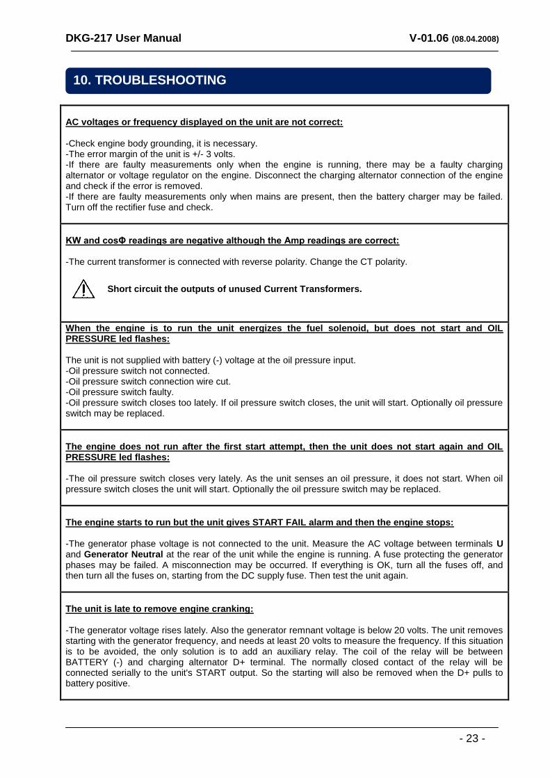
AC voltages or frequency displayed on the unit are not correct: -Check engine body grounding, it is necessary. -The error margin of the unit is +/- 3 volts. -If there are faulty measurements only when the engine is running, there may be a faulty charging alternator or voltage regulator on the engine. Disconnect the charging alternator connection of the engine and check if the error is removed. -If there are faulty measurements only when mains are present, then the battery charger may be failed. Turn off the rectifier fuse and check.
KW and cosΦ readings are negative although the Amp readings are correct: -The current transformer is connected with reverse polarity. Change the CT polarity.
Short circuit the outputs of unused Current Transformers.
When the engine is to run the unit energizes the fuel solenoid, but does not start and OIL PRESSURE led flashes: The unit is not supplied with battery (-) voltage at the oil pressure input. -Oil pressure switch not connected. -Oil pressure switch connection wire cut. -Oil pressure switch faulty. -Oil pressure switch closes too lately. If oil pressure switch closes, the unit will start. Optionally oil pressure switch may be replaced.
The engine does not run after the first start attempt, then the unit does not start again and OIL PRESSURE led flashes: -The oil pressure switch closes very lately. As the unit senses an oil pressure, it does not start. When oil pressure switch closes the unit will start. Optionally the oil pressure switch may be replaced.
The engine starts to run but the unit gives START FAIL alarm and then the engine stops: -The generator phase voltage is not connected to the unit. Measure the AC voltage between terminals U and Generator Neutral at the rear of the unit while the engine is running. A fuse protecting the generator phases may be failed. A misconnection may be occurred. If everything is OK, turn all the fuses off, and then turn all the fuses on, starting from the DC supply fuse. Then test the unit again.
The unit is late to remove engine cranking: -The generator voltage rises lately. Also the generator remnant voltage is below 20 volts. The unit removes starting with the generator frequency, and needs at least 20 volts to measure the frequency. If this situation is to be avoided, the only solution is to add an auxiliary relay. The coil of the relay will be between BATTERY (-) and charging alternator D+ terminal. The normally closed contact of the relay will be connected serially to the unit's START output. So the starting will also be removed when the D+ pulls to battery positive.
10. TROUBLESHOOTING
DKG-217 User Manual V-01.06 (08.04.2008)
- 24 -
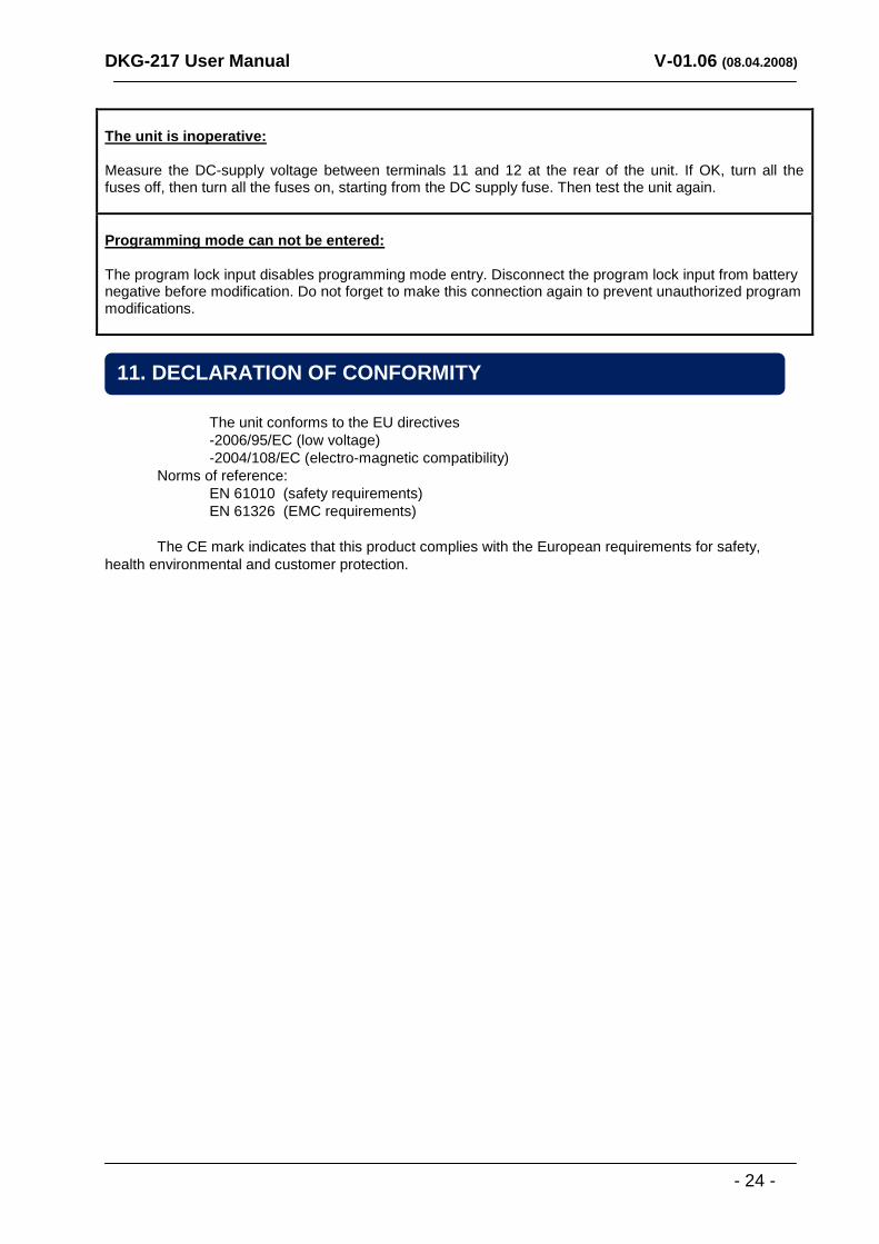
The unit is inoperative: Measure the DC-supply voltage between terminals 11 and 12 at the rear of the unit. If OK, turn all the fuses off, then turn all the fuses on, starting from the DC supply fuse. Then test the unit again.
Programming mode can not be entered: The program lock input disables programming mode entry. Disconnect the program lock input from battery negative before modification. Do not forget to make this connection again to prevent unauthorized program modifications.
The unit conforms to the EU directives
-2006/95/EC (low voltage)
-2004/108/EC (electro-magnetic compatibility)
Norms of reference:
EN 61010 (safety requirements)
EN 61326 (EMC requirements)
The CE mark indicates that this product complies with the European requirements for safety,
health environmental and customer protection.
11. DECLARATION OF CONFORMITY
DKG-217 User Manual V-01.06 (08.04.2008)
- 25 -
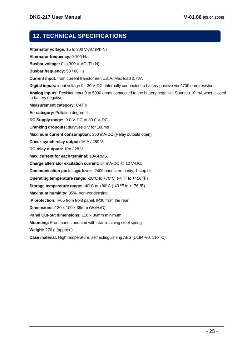
Alternator voltage: 15 to 300 V-AC (Ph-N)
Alternator frequency: 0-100 Hz.
Busbar voltage: 0 to 300 V-AC (Ph-N)
Busbar frequency: 50 / 60 Hz
Current input: from current transformer, .../5A. Max load 0.7VA
Digital inputs: input voltage 0 - 30 V-DC. Internally connected to battery positive via 4700 ohm resistor.
Analog inputs: Resistor input 0 to 5000 ohms connected to the battery negative. Sources 10 mA when closed to battery negative.
Measurement category: CAT II
Air category: Pollution degree II
DC Supply range: 9.0 V-DC to 30.0 V-DC
Cranking dropouts: survives 0 V for 100ms
Maximum current consumption: 350 mA-DC (Relay outputs open)
Check synch relay output: 16 A / 250 V.
DC relay outputs: 10A / 28 V.
Max. current for each terminal: 10A-RMS.
Charge alternator excitation current: 54 mA-DC @ 12 V-DC.
Communication port: Logic levels. 2400 bauds, no parity, 1 stop bit.
Operating temperature range: -20C to +70C (-4 ºF to +158 ºF)
Storage temperature range: -40C to +80C (-40 ºF to +176 ºF)
Maximum humidity: 95%, non-condensing
IP protection: IP65 from front panel, IP30 from the rear
Dimensions: 130 x 100 x 39mm (WxHxD)
Panel Cut-out dimensions: 116 x 86mm minimum.
Mounting: Front panel mounted with rear retaining steel spring
Weight: 270 g (approx.)
Case material: High temperature, self extinguishing ABS (UL94-V0, 110 C)
12. TECHNICAL SPECIFICATIONS
DKG-217 User Manual V-01.06 (08.04.2008)
- 26 -
DATAKOM Electronics Ltd.
Tel: +90-216-466 84 60 Fax: +90-216-364 65 65 e-mail: [email protected] http: www.datakom.com.tr
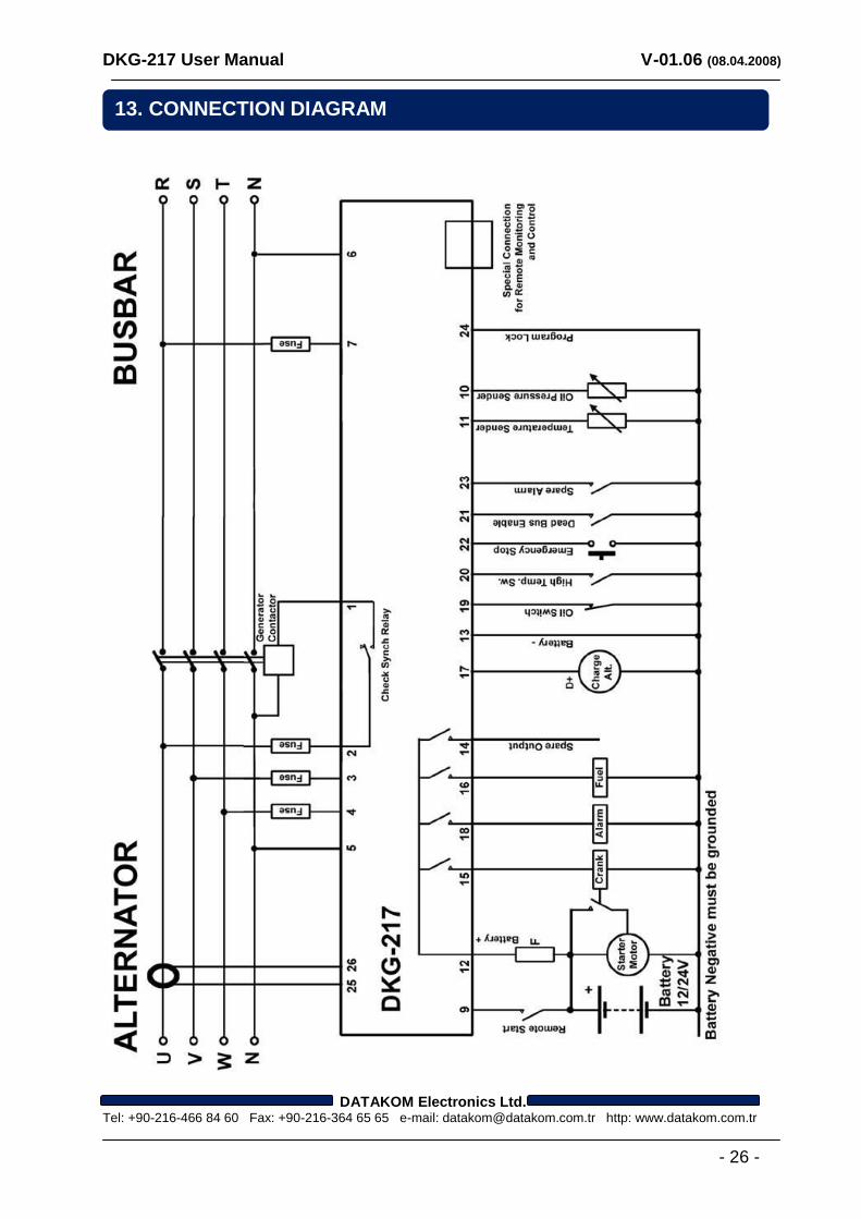
13. CONNECTION DIAGRAM