MMU 0102, MMA 0204, MMB 0207 - · PDF fileMMU 0102, MMA 0204, MMB 0207 - Precision Precision...
11
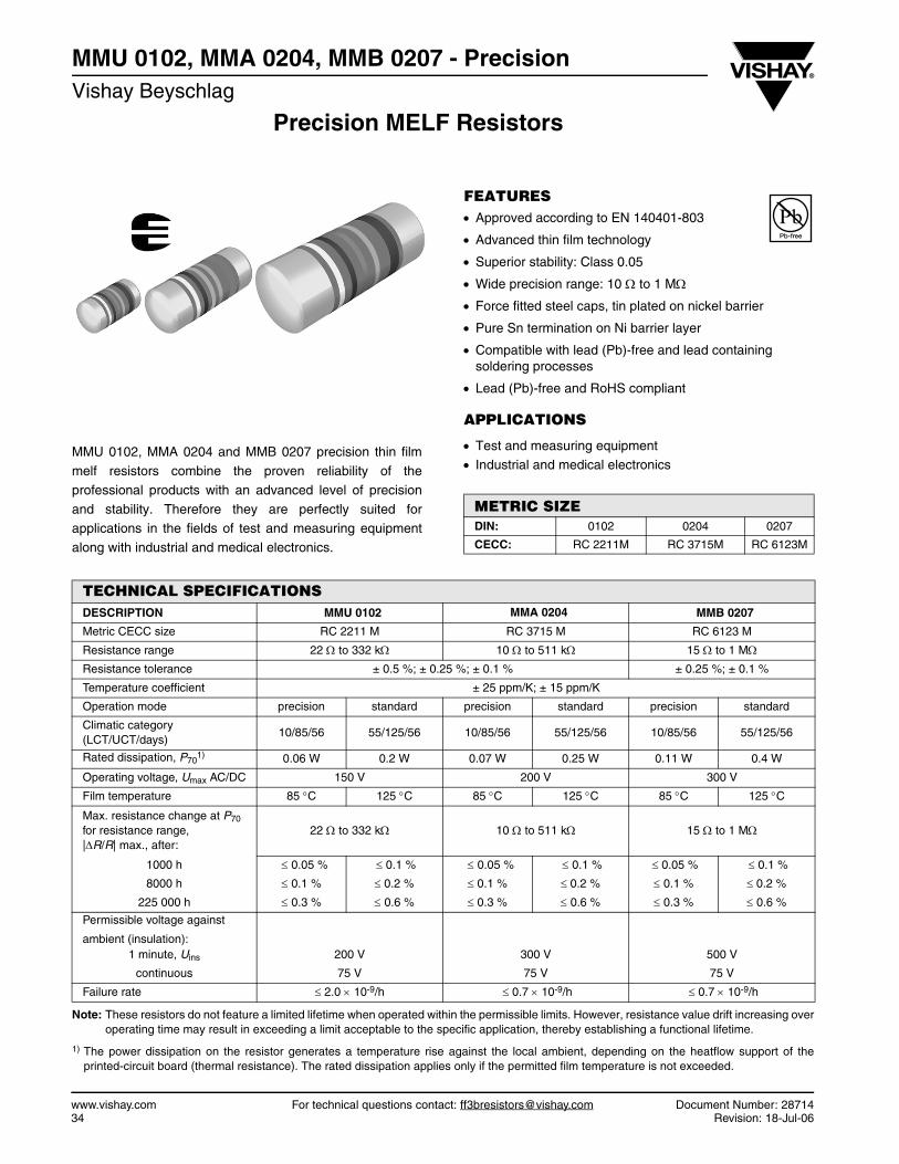
Precision MELF Resistors MMU 0102, MMA 0204, MMB 0207 - Precision Vishay Beyschlag www.vishay.com For technical questions contact: [email protected] Document Number: 28714 34 Revision: 18-Jul-06 FEATURES • Approved according to EN 140401-803 • Advanced thin film technology • Superior stability: Class 0.05 • Wide precision range: 10 Ω to 1 MΩ • Force fitted steel caps, tin plated on nickel barrier • Pure Sn termination on Ni barrier layer • Compatible with lead (Pb)-free and lead containing soldering processes • Lead (Pb)-free and RoHS compliant APPLICATIONS • Test and measuring equipment • Industrial and medical electronics METRIC SIZE DIN: 0102 0204 0207 CECC: RC 2211M RC 3715M RC 6123M MMU 0102, MMA 0204 and MMB 0207 precision thin film melf resistors combine the proven reliability of the professional products with an advanced level of precision and stability. Therefore they are perfectly suited for applications in the fields of test and measuring equipment along with industrial and medical electronics. Note: These resistors do not feature a limited lifetime when operated within the permissible limits. However, resistance value drift increasing over operating time may result in exceeding a limit acceptable to the specific application, thereby establishing a functional lifetime. 1) The power dissipation on the resistor generates a temperature rise against the local ambient, depending on the heatflow support of the printed-circuit board (thermal resistance). The rated dissipation applies only if the permitted film temperature is not exceeded. TECHNICAL SPECIFICATIONS DESCRIPTION MMU 0102 MMA 0204 MMB 0207 Metric CECC size RC 2211 M RC 3715 M RC 6123 M Resistance range 22 Ω to 332 kΩ 10 Ω to 511 kΩ 15 Ω to 1 MΩ Resistance tolerance ± 0.5 %; ± 0.25 %; ± 0.1 % ± 0.25 %; ± 0.1 % Temperature coefficient ± 25 ppm/K; ± 15 ppm/K Operation mode precision standard precision standard precision standard Climatic category (LCT/UCT/days) 10/85/56 55/125/56 10/85/56 55/125/56 10/85/56 55/125/56 Rated dissipation, P 70 1) 0.06 W 0.2 W 0.07 W 0.25 W 0.11 W 0.4 W Operating voltage, U max AC/DC 150 V 200 V 300 V Film temperature 85 °C 125 °C 85 °C 125 °C 85 °C 125 °C Max. resistance change at P 70 for resistance range, |ΔR/R| max., after: 22 Ω to 332 kΩ 10 Ω to 511 kΩ 15 Ω to 1 MΩ 1000 h ≤ 0.05 % ≤ 0.1 % ≤ 0.05 % ≤ 0.1 % ≤ 0.05 % ≤ 0.1 % 8000 h ≤ 0.1 % ≤ 0.2 % ≤ 0.1 % ≤ 0.2 % ≤ 0.1 % ≤ 0.2 % 225 000 h ≤ 0.3 % ≤ 0.6 % ≤ 0.3 % ≤ 0.6 % ≤ 0.3 % ≤ 0.6 % Permissible voltage against ambient (insulation): 1 minute, U ins 200 V 300 V 500 V continuous 75 V 75 V 75 V Failure rate ≤ 2.0 × 10 -9 /h ≤ 0.7 × 10 -9 /h ≤ 0.7 × 10 -9 /h
Transcript of MMU 0102, MMA 0204, MMB 0207 - · PDF fileMMU 0102, MMA 0204, MMB 0207 - Precision Precision...
Precision MELF Resistors
MMU 0102, MMA 0204, MMB 0207 - PrecisionVishay Beyschlag
www.vishay.com For technical questions contact: [email protected] Document Number: 2871434 Revision: 18-Jul-06
FEATURES• Approved according to EN 140401-803
• Advanced thin film technology
• Superior stability: Class 0.05
• Wide precision range: 10 Ω to 1 MΩ
• Force fitted steel caps, tin plated on nickel barrier
• Pure Sn termination on Ni barrier layer
• Compatible with lead (Pb)-free and lead containing soldering processes
• Lead (Pb)-free and RoHS compliant
APPLICATIONS
• Test and measuring equipment• Industrial and medical electronics
METRIC SIZEDIN: 0102 0204 0207
CECC: RC 2211M RC 3715M RC 6123M
MMU 0102, MMA 0204 and MMB 0207 precision thin film
melf resistors combine the proven reliability of the
professional products with an advanced level of precision
and stability. Therefore they are perfectly suited forapplications in the fields of test and measuring equipment
along with industrial and medical electronics.
Note: These resistors do not feature a limited lifetime when operated within the permissible limits. However, resistance value drift increasing overoperating time may result in exceeding a limit acceptable to the specific application, thereby establishing a functional lifetime.
1) The power dissipation on the resistor generates a temperature rise against the local ambient, depending on the heatflow support of theprinted-circuit board (thermal resistance). The rated dissipation applies only if the permitted film temperature is not exceeded.
TECHNICAL SPECIFICATIONSDESCRIPTION MMU 0102 MMA 0204 MMB 0207
Metric CECC size RC 2211 M RC 3715 M RC 6123 M
Resistance range 22 Ω to 332 kΩ 10 Ω to 511 kΩ 15 Ω to 1 MΩ
Resistance tolerance ± 0.5 %; ± 0.25 %; ± 0.1 % ± 0.25 %; ± 0.1 %
Temperature coefficient ± 25 ppm/K; ± 15 ppm/K
Operation mode precision standard precision standard precision standard
Climatic category (LCT/UCT/days)
10/85/56 55/125/56 10/85/56 55/125/56 10/85/56 55/125/56
Rated dissipation, P701) 0.06 W 0.2 W 0.07 W 0.25 W 0.11 W 0.4 W
Operating voltage, Umax AC/DC 150 V 200 V 300 V
Film temperature 85 °C 125 °C 85 °C 125 °C 85 °C 125 °C
Max. resistance change at P70for resistance range, |ΔR/R| max., after:
22 Ω to 332 kΩ 10 Ω to 511 kΩ 15 Ω to 1 MΩ
1000 h ≤ 0.05 % ≤ 0.1 % ≤ 0.05 % ≤ 0.1 % ≤ 0.05 % ≤ 0.1 %
8000 h ≤ 0.1 % ≤ 0.2 % ≤ 0.1 % ≤ 0.2 % ≤ 0.1 % ≤ 0.2 %
225 000 h ≤ 0.3 % ≤ 0.6 % ≤ 0.3 % ≤ 0.6 % ≤ 0.3 % ≤ 0.6 %
Permissible voltage against
ambient (insulation):1 minute, Uins 200 V 300 V 500 V
continuous 75 V 75 V 75 V
Failure rate ≤ 2.0 × 10⁻⁹/h ≤ 0.7 × 10⁻⁹/h ≤ 0.7 × 10⁻⁹/h
MMU 0102, MMA 0204, MMB 0207 - PrecisionPrecision MELF Resistors Vishay Beyschlag
Document Number: 28714 For technical questions contact: [email protected] www.vishay.comRevision: 18-Jul-06 35
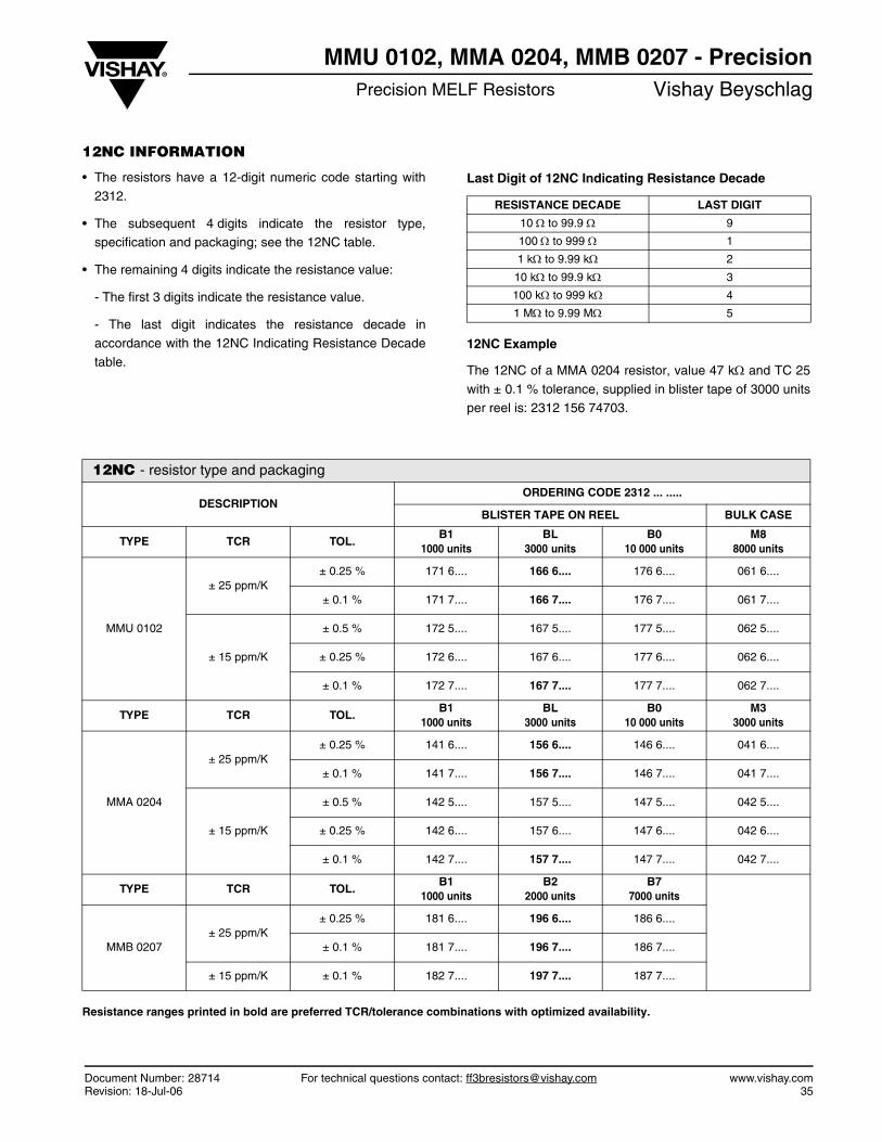
12NC INFORMATION
• The resistors have a 12-digit numeric code starting with
2312.
• The subsequent 4 digits indicate the resistor type,specification and packaging; see the 12NC table.
• The remaining 4 digits indicate the resistance value:
- The first 3 digits indicate the resistance value.
- The last digit indicates the resistance decade in
accordance with the 12NC Indicating Resistance Decade
table.
Last Digit of 12NC Indicating Resistance Decade
12NC Example
The 12NC of a MMA 0204 resistor, value 47 kΩ and TC 25
with ± 0.1 % tolerance, supplied in blister tape of 3000 unitsper reel is: 2312 156 74703.
Resistance ranges printed in bold are preferred TCR/tolerance combinations with optimized availability.
RESISTANCE DECADE LAST DIGIT
10 Ω to 99.9 Ω 9
100 Ω to 999 Ω 1
1 kΩ to 9.99 kΩ 2
10 kΩ to 99.9 kΩ 3
100 kΩ to 999 kΩ 4
1 MΩ to 9.99 MΩ 5
12NC - resistor type and packaging
DESCRIPTIONORDERING CODE 2312 ... .....
BLISTER TAPE ON REEL BULK CASE
TYPE TCR TOL.B1
1000 unitsBL
3000 unitsB0
10 000 unitsM8
8000 units
MMU 0102
± 25 ppm/K± 0.25 % 171 6.... 166 6.... 176 6.... 061 6....
± 0.1 % 171 7.... 166 7.... 176 7.... 061 7....
± 15 ppm/K
± 0.5 % 172 5.... 167 5.... 177 5.... 062 5....
± 0.25 % 172 6.... 167 6.... 177 6.... 062 6....
± 0.1 % 172 7.... 167 7.... 177 7.... 062 7....
TYPE TCR TOL.B1
1000 unitsBL
3000 unitsB0
10 000 unitsM3
3000 units
MMA 0204
± 25 ppm/K± 0.25 % 141 6.... 156 6.... 146 6.... 041 6....
± 0.1 % 141 7.... 156 7.... 146 7.... 041 7....
± 15 ppm/K
± 0.5 % 142 5.... 157 5.... 147 5.... 042 5....
± 0.25 % 142 6.... 157 6.... 147 6.... 042 6....
± 0.1 % 142 7.... 157 7.... 147 7.... 042 7....
TYPE TCR TOL.B1
1000 unitsB2
2000 unitsB7
7000 units
MMB 0207± 25 ppm/K
± 0.25 % 181 6.... 196 6.... 186 6....
± 0.1 % 181 7.... 196 7.... 186 7....
± 15 ppm/K ± 0.1 % 182 7.... 197 7.... 187 7....
MMU 0102, MMA 0204, MMB 0207 - PrecisionVishay Beyschlag Precision MELF Resistors
www.vishay.com For technical questions contact: [email protected] Document Number: 2871436 Revision: 18-Jul-06
Notes
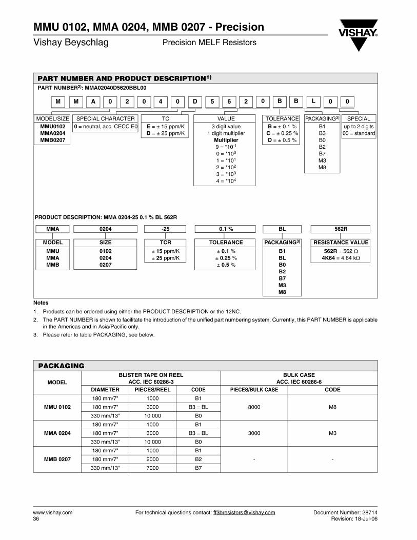
1. Products can be ordered using either the PRODUCT DESCRIPTION or the 12NC.
2. The PART NUMBER is shown to facilitate the introduction of the unified part numbering system. Currently, this PART NUMBER is applicablein the Americas and in Asia/Pacific only.
3. Please refer to table PACKAGING, see below.
PART NUMBER AND PRODUCT DESCRIPTION1)
PART NUMBER2): MMA02040D5620BBL00
MODEL/SIZE SPECIAL CHARACTER TC VALUE TOLERANCE PACKAGING3) SPECIALMMU0102MMA0204MMB0207
0 = neutral, acc. CECC E0 E = ± 15 ppm/KD = ± 25 ppm/K
3 digit value1 digit multiplier
Multiplier9 = *10-1
0 = *100
1 = *101
2 = *102
3 = *103
4 = *104
B = ± 0.1 %C = ± 0.25 %D = ± 0.5 %
B1B3B0B2B7M3M8
up to 2 digits00 = standard
PRODUCT DESCRIPTION: MMA 0204-25 0.1 % BL 562R
MMA 0204 -25 0.1 % BL 562R
MODEL SIZE TCR TOLERANCE PACKAGING3) RESISTANCE VALUE
MMUMMAMMB
010202040207
± 15 ppm/K± 25 ppm/K
± 0.1 %± 0.25 %± 0.5 %
B1BLB0B2B7M3M8
562R = 562 Ω4K64 = 4.64 kΩ
PACKAGING
MODELBLISTER TAPE ON REEL
ACC. IEC 60286-3BULK CASE
ACC. IEC 60286-6DIAMETER PIECES/REEL CODE PIECES/BULK CASE CODE
MMU 0102
180 mm/7" 1000 B1
8000 M8180 mm/7" 3000 B3 = BL
330 mm/13" 10 000 B0
MMA 0204
180 mm/7" 1000 B1
3000 M3180 mm/7" 3000 B3 = BL
330 mm/13" 10 000 B0
MMB 0207
180 mm/7" 1000 B1
- -180 mm/7" 2000 B2
330 mm/13" 7000 B7
0 B B L 0 024 0 D 5 6M M A 0 2 0
MMU 0102, MMA 0204, MMB 0207 - PrecisionPrecision MELF Resistors Vishay Beyschlag
Document Number: 28714 For technical questions contact: [email protected] www.vishay.comRevision: 18-Jul-06 37
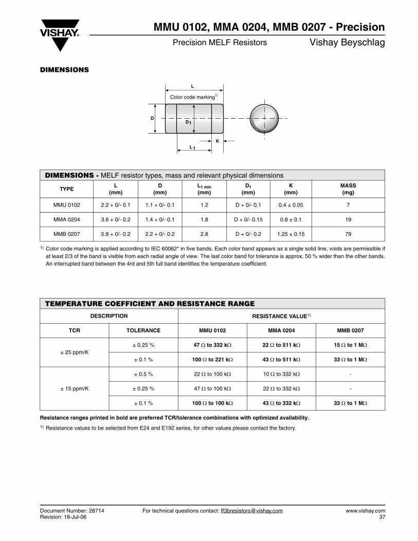
DIMENSIONS
1) Color code marking is applied according to IEC 60062* in five bands. Each color band appears as a single solid line, voids are permissible ifat least 2/3 of the band is visible from each radial angle of view. The last color band for tolerance is approx, 50 % wider than the other bands.An interrupted band between the 4rd and 5th full band identifies the temperature coefficient.
Resistance ranges printed in bold are preferred TCR/tolerance combinations with optimized availability.
1) Resistance values to be selected from E24 and E192 series, for other values please contact the factory.
DIMENSIONS - MELF resistor types, mass and relevant physical dimensions
TYPEL
(mm)D
(mm)L1 min(mm)
D1(mm)
K(mm)
MASS (mg)
MMU 0102 2.2 + 0/- 0.1 1.1 + 0/- 0.1 1.2 D + 0/- 0.1 0.4 ± 0.05 7
MMA 0204 3.6 + 0/- 0.2 1.4 + 0/- 0.1 1.8 D + 0/- 0.15 0.8 ± 0.1 19
MMB 0207 5.8 + 0/- 0.2 2.2 + 0/- 0.2 2.8 D + 0/- 0.2 1.25 ± 0.15 79
TEMPERATURE COEFFICIENT AND RESISTANCE RANGE
DESCRIPTION RESISTANCE VALUE1)
TCR TOLERANCE MMU 0102 MMA 0204 MMB 0207
± 25 ppm/K± 0.25 % 47 Ω to 332 kΩ 22 Ω to 511 kΩ 15 Ω to 1 MΩ
± 0.1 % 100 Ω to 221 kΩ 43 Ω to 511 kΩ 33 Ω to 1 MΩ
± 15 ppm/K
± 0.5 % 22 Ω to 100 kΩ 10 Ω to 332 kΩ -
± 0.25 % 47 Ω to 100 kΩ 22 Ω to 332 kΩ -
± 0.1 % 100 Ω to 100 kΩ 43 Ω to 332 kΩ 33 Ω to 1 MΩ
L
D
L1
K
D1
Color code marking1)
MMU 0102, MMA 0204, MMB 0207 - PrecisionVishay Beyschlag Precision MELF Resistors
www.vishay.com For technical questions contact: [email protected] Document Number: 2871438 Revision: 18-Jul-06
DESCRIPTION
Production is strictly controlled and follows an extensive setof instructions established for reproducibility. A homo-geneous film of metal alloy is deposited on a high gradeceramic body (85 % Al2O3, for MICRO-MELF: 96 % Al2O3)and conditioned to achieve the desired temperaturecoefficient. Nickel plated steel termination caps are firmlypressed on the metallised rods. A special laser is used toachieve the target value by smoothly cutting a helical groovein the resistive layer without damaging the ceramics. Afurther conditioning is applied in order to stabilise thetrimming result. The resistor elements are covered by aprotective coating designed for electrical, mechanical andclimatic protection. The terminations receive a final pure tinon nickel plating. Five color code rings designate theresistance value and tolerance in accordance withIEC 60062*.
The result of the determined production is verified by anextensive testing procedure performed on 100 % of theindividual resistors. Only accepted products are laid directlyinto the blister tape in accordance with IEC 60 286-3* or bulkcase in accordance with IEC 60286-6*.
ASSEMBLY
The resistors are suitable for processing on automaticSMD assembly systems. They are suitable for automaticsoldering using wave, reflow or vapour phase as shown inIEC 61760-1*. Excellent solderability is proven, even afterextended storage in excess of 10 years. The encapsulationis resistant to all cleaning solvents commonly used in theelectronics industry, including alcohols, esters and aqueoussolutions. The resistors are completely lead (Pb)-free, thepure tin plating provides compatibility with lead (Pb)-freesoldering processes. The immunity of the plating against tinwhisker growth has been proven under extensive testing.
All products comply with the GADSL1) and the CEFIC-EECA-EICTA2) list of legal restrictions on hazardoussubstances. This includes full compliance with the followingdirectives:• 2000/53/EC End of Vehicle life Directive (ELV) and Annex II
(ELV II)
• 2002/95/EC Restriction of the use of Hazardous Substances Directive (RoHS)
• 2002/96/EC Waste Electrical and Electronic Equipment Directive (WEEE)
1) Global Automotive Declarable Substance List, see www.gadsl.org2) CEFIC (European Chemical Industry Council), EECA (European
Electronic Component Manufacturers Association), EICTA(European trade organisation representing the information andcommunications technology and consumer electronics), seewww.eicta.org -> issues -> environment policy -> chemicals ->chemicals for electronics
APPROVALS
The resistors are tested in accordance with EN 140401-803(superseding CECC 40401-803) which refers toEN 60115-1, EN 140400 and the variety of enviromental testprocedures of the IEC 60068* series. Approval of conformityis indicated by the CECC logo on the package label.
Vishay BEYSCHLAG has achieved "Approval ofManufacturer" in accordance with IEC QC 001002-3,clause 2. The release certificate for "Technology ApprovalSchedule" in accordance with CECC 240001 based onIEC QC 001002-3, clause 6 is granted for the VishayBEYSCHLAG manufacturing process.
SPECIALS
On request, resistors are available with established reliability in accordance with EN 140401-803 Version E. Please refer to the special data sheet for information on failure rate level, available resistance ranges and ordering codes.
Note:* The quoted IEC standards are also released as EN standards withthe same number and identical contents.
MMU 0102, MMA 0204, MMB 0207 - PrecisionPrecision MELF Resistors Vishay Beyschlag
Document Number: 28714 For technical questions contact: [email protected] www.vishay.comRevision: 18-Jul-06 39
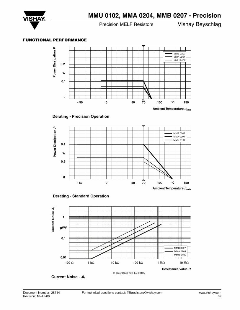
FUNCTIONAL PERFORMANCE
C100 150
0
- 50 0 50
0.1
W
70
0.2
Po
wer
Dis
sip
atio
nP
Ambient Temperature ambϑ
MMA 0204MMB 0207
MMU 0102
Derating - Precision Operation
Ambient Temperature ambϑ
C100 150
0
- 50 0 50
0.2
W
70
0.4
Po
wer
Dis
sip
atio
nP
MMA 0204MMB 0207
MMU 0102
Derating - Standard Operation
alue R
Cu
rren
t N
ois
e A
1
0.01
100 Ω
0.1
1
µV/V
Resistance V
Current Noise - A1
In accordance with IEC 60195
1 kΩ 10 kΩ 100 kΩ 1 MΩ 10 MΩ
MMB 0207
MMU 0102MMA 0204
MMU 0102, MMA 0204, MMB 0207 - PrecisionVishay Beyschlag Precision MELF Resistors
www.vishay.com For technical questions contact: [email protected] Document Number: 2871440 Revision: 18-Jul-06
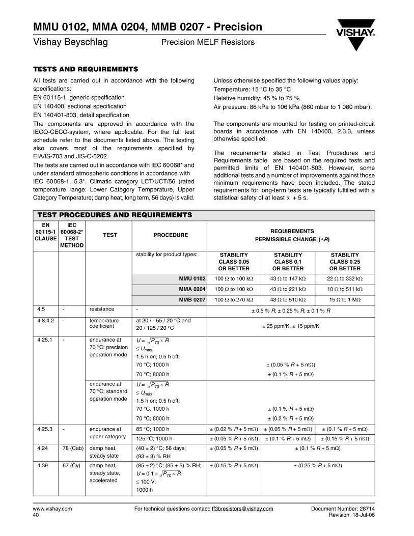
TESTS AND REQUIREMENTS
All tests are carried out in accordance with the followingspecifications:EN 60115-1, generic specification
EN 140400, sectional specification
EN 140401-803, detail specificationThe components are approved in accordance with theIECQ-CECC-system, where applicable. For the full testschedule refer to the documents listed above. The testingalso covers most of the requirements specified byEIA/IS-703 and JIS-C-5202.
The tests are carried out in accordance with IEC 60068* andunder standard atmospheric conditions in accordance with IEC 60068-1, 5.3*. Climatic category LCT/UCT/56 (ratedtemperature range: Lower Category Temperature, UpperCategory Temperature; damp heat, long term, 56 days) is valid.
Unless otherwise specified the following values apply:Temperature: 15 °C to 35 °C
Relative humidity: 45 % to 75 %
Air pressure: 86 kPa to 106 kPa (860 mbar to 1 060 mbar).
The components are mounted for testing on printed-circuitboards in accordance with EN 140400, 2.3.3, unlessotherwise specified.
The requirements stated in Test Procedures andRequirements table are based on the required tests andpermitted limits of EN 140401-803. However, someadditional tests and a number of improvements against thoseminimum requirements have been included. The statedrequirements for long-term tests are typically fulfilled with astatistical safety of at least + 5 s.x
TEST PROCEDURES AND REQUIREMENTSEN
60115-1CLAUSE
IEC60068-2*
TESTMETHOD
TEST PROCEDUREREQUIREMENTS
PERMISSIBLE CHANGE (ΔR)
stability for product types: STABILITY CLASS 0.05 OR BETTER
STABILITY CLASS 0.1
OR BETTER
STABILITY CLASS 0.25 OR BETTER
MMU 0102 100 Ω to 100 kΩ 43 Ω to 147 kΩ 22 Ω to 332 kΩ
MMA 0204 100 Ω to 100 kΩ 43 Ω to 221 kΩ 10 Ω to 511 kΩ
MMB 0207 100 Ω to 270 kΩ 43 Ω to 510 kΩ 15 Ω to 1 MΩ
4.5 - resistance - ± 0.5 % R; ± 0.25 % R; ± 0.1 % R
4.8.4.2 - temperature coefficient
at 20 / - 55 / 20 °C and20 / 125 / 20 °C ± 25 ppm/K, ± 15 ppm/K
4.25.1 - endurance at70 °C: precision operation mode
U = ≤ Umax;
1.5 h on; 0.5 h off;
70 °C; 1000 h ± (0.05 % R + 5 mΩ)
70 °C; 8000 h ± (0.1 % R + 5 mΩ)
endurance at 70 °C: standard operation mode
U =
≤ Umax;
1.5 h on; 0.5 h off;
70 °C; 1000 h ± (0.1 % R + 5 mΩ)
70 °C; 8000 h ± (0.2 % R + 5 mΩ)
4.25.3 - endurance at upper category
85 °C; 1000 h ± (0.02 % R + 5 mΩ) ± (0.05 % R + 5 mΩ) ± (0.1 % R + 5 mΩ)
125 °C; 1000 h ± (0.05 % R + 5 mΩ) ± (0.1 % R + 5 mΩ) ± (0.15 % R + 5 mΩ)
4.24 78 (Cab) damp heat, steady state
(40 ± 2) °C; 56 days;
(93 ± 3) % RH
± (0.05 % R + 5 mΩ) ± (0.1 % R + 5 mΩ)
4.39 67 (Cy) damp heat, steady state, accelerated
(85 ± 2) °C; (85 ± 5) % RH;
U = 0.1 ×
≤ 100 V;
1000 h
± (0.15 % R + 5 mΩ) ± (0.25 % R + 5 mΩ)
P70 R×
P70 R×
P70 R×
MMU 0102, MMA 0204, MMB 0207 - PrecisionPrecision MELF Resistors Vishay Beyschlag
Document Number: 28714 For technical questions contact: [email protected] www.vishay.comRevision: 18-Jul-06 41
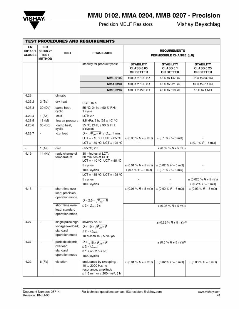
4.23 climatic
4.23.2 2 (Ba) dry heat UCT; 16 h
4.23.3 30 (Db) damp heat, cyclic
55 °C; 24 h; ≥ 90 % RH; 1 cycle
4.23.4 1 (Aa) cold LCT; 2 h
4.23.5 13 (M) low air pressure 8.5 kPa; 2 h; (25 ± 10) °C4.23.6 30 (Db) damp heat,
cyclic55 °C; 24 h; ≥ 90 % RH; 5 cycles
4.23.7 - d.c. load U = ≤ Umax; 1 min.
LCT = - 10 °C; UCT = 85 °C ± (0.05 % R + 5 mΩ) ± (0.1 % R + 5 mΩ) -
LCT = - 55 °C; UCT = 125 °C - - ± (0.1 % R + 5 mΩ)
- 1 (Aa) cold - 55 °C; 2 h ± (0.02 % R + 5 mΩ)
4.19 14 (Na) rapid change of temperature
30 minutes at LCT; 30 minutes at UCT;LCT = - 10 °C; UCT = 85 °C5 cycles ± (0.01 % R + 5 mΩ) ± (0.02 % R + 5 mΩ) -
1000 cycles ± (0.1 % R + 5 mΩ) ± (0.1 % R + 5 mΩ) -
LCT = - 55 °C; UCT = 125 °C5 cycles - - ± (0.025 % R + 5 mΩ)
1000 cycles - - ± (0.2 % R + 5 mΩ)
4.13 - short time over- load; precision operation mode
U = 2.5 ×
≤ 2 × Umax; 5 s
± (0.01 % R + 5 mΩ) ± (0.02 % R + 5 mΩ) ± (0.03 % R + 5 mΩ)
short time over- load; standard operation mode
± (0.05 % R + 5 mΩ)
4.27 - single pulse high voltage overload; standard operation mode
severity no. 4:
U = 10 × ≤ 2 × Umax;
10 pulses 10 μs/700 μs
± (0.25 % R + 5 mΩ)1)
4.37 - periodic electric overload; standard operation mode
U =
≤ 2 × Umax;
0.1 s on; 2.5 s off;
1000 cycles
± (0.5 % R + 5 mΩ)1)
4.22 6 (Fc) vibration endurance by sweeping; 10 to 2000 Hz; no resonance; amplitude ≤ 1.5 mm or ≤ 200 m/s2; 6 h
± (0.01 % R + 5 mΩ) ± (0.02 % R + 5 mΩ) ± (0.03 % R + 5 mΩ)
TEST PROCEDURES AND REQUIREMENTSEN
60115-1CLAUSE
IEC60068-2*
TESTMETHOD
TEST PROCEDUREREQUIREMENTS
PERMISSIBLE CHANGE (ΔR)
stability for product types: STABILITY CLASS 0.05 OR BETTER
STABILITY CLASS 0.1
OR BETTER
STABILITY CLASS 0.25 OR BETTER
MMU 0102 100 Ω to 100 kΩ 43 Ω to 147 kΩ 22 Ω to 332 kΩ
MMA 0204 100 Ω to 100 kΩ 43 Ω to 221 kΩ 10 Ω to 511 kΩ
MMB 0207 100 Ω to 270 kΩ 43 Ω to 510 kΩ 15 Ω to 1 MΩ
P70 R×
P70 R×
P70 R×
15 P70× R×
MMU 0102, MMA 0204, MMB 0207 - PrecisionVishay Beyschlag Precision MELF Resistors
www.vishay.com For technical questions contact: [email protected] Document Number: 2871442 Revision: 18-Jul-06
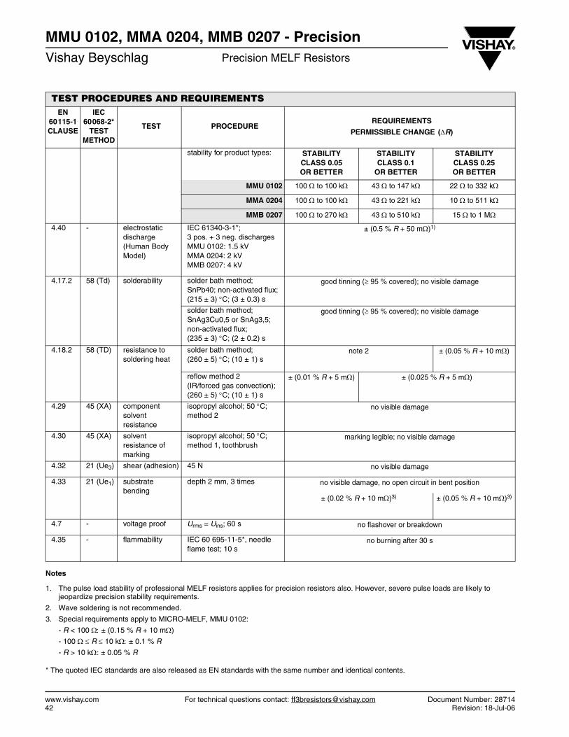
Notes
1. The pulse load stability of professional MELF resistors applies for precision resistors also. However, severe pulse loads are likely to jeopardize precision stability requirements.
2. Wave soldering is not recommended.
3. Special requirements apply to MICRO-MELF, MMU 0102:
- R < 100 Ω: ± (0.15 % R + 10 mΩ)
- 100 Ω ≤ R ≤ 10 kΩ: ± 0.1 % R
- R > 10 kΩ: ± 0.05 % R
* The quoted IEC standards are also released as EN standards with the same number and identical contents.
4.40 - electrostatic discharge (Human Body Model)
IEC 61340-3-1*;3 pos. + 3 neg. dischargesMMU 0102: 1.5 kVMMA 0204: 2 kVMMB 0207: 4 kV
± (0.5 % R + 50 mΩ)1)
4.17.2 58 (Td) solderability solder bath method; SnPb40; non-activated flux;(215 ± 3) °C; (3 ± 0.3) s
good tinning (≥ 95 % covered); no visible damage
solder bath method; SnAg3Cu0,5 or SnAg3,5; non-activated flux; (235 ± 3) °C; (2 ± 0.2) s
good tinning (≥ 95 % covered); no visible damage
4.18.2 58 (TD) resistance to soldering heat
solder bath method;(260 ± 5) °C; (10 ± 1) s
note 2 ± (0.05 % R + 10 mΩ)
reflow method 2(IR/forced gas convection);(260 ± 5) °C; (10 ± 1) s
± (0.01 % R + 5 mΩ) ± (0.025 % R + 5 mΩ)
4.29 45 (XA) component solvent resistance
isopropyl alcohol; 50 °C; method 2
no visible damage
4.30 45 (XA) solvent resistance of marking
isopropyl alcohol; 50 °C; method 1, toothbrush
marking legible; no visible damage
4.32 21 (Ue3) shear (adhesion) 45 N no visible damage
4.33 21 (Ue1) substrate bending
depth 2 mm, 3 times no visible damage, no open circuit in bent position
± (0.02 % R + 10 mΩ)3) ± (0.05 % R + 10 mΩ)3)
4.7 - voltage proof Urms = Uins; 60 s no flashover or breakdown
4.35 - flammability IEC 60 695-11-5*, needle flame test; 10 s
no burning after 30 s
TEST PROCEDURES AND REQUIREMENTSEN
60115-1CLAUSE
IEC60068-2*
TESTMETHOD
TEST PROCEDUREREQUIREMENTS
PERMISSIBLE CHANGE (ΔR)
stability for product types: STABILITY CLASS 0.05 OR BETTER
STABILITY CLASS 0.1
OR BETTER
STABILITY CLASS 0.25 OR BETTER
MMU 0102 100 Ω to 100 kΩ 43 Ω to 147 kΩ 22 Ω to 332 kΩ
MMA 0204 100 Ω to 100 kΩ 43 Ω to 221 kΩ 10 Ω to 511 kΩ
MMB 0207 100 Ω to 270 kΩ 43 Ω to 510 kΩ 15 Ω to 1 MΩ
MMU 0102, MMA 0204, MMB 0207 - PrecisionPrecision MELF Resistors Vishay Beyschlag
Document Number: 28714 For technical questions contact: [email protected] www.vishay.comRevision: 18-Jul-06 43
REVISION HISTORYCompared to the prior revision of this datasheet, 26-Feb-04, the following changes have been applied:
• Introduction of a standardized part numbering system• Additional emphasis on the clean balance of materials and on the compliance with various EU directives.• Revision of the current noise diagram based on new test results• Introduction of a test and requirements for electrostatic discharge (ESD)• No other change of technical contents• No product change
Document Number: 91000 www.vishay.comRevision: 18-Jul-08 1
Disclaimer
Legal Disclaimer NoticeVishay
All product specifications and data are subject to change without notice.
Vishay Intertechnology, Inc., its affiliates, agents, and employees, and all persons acting on its or their behalf(collectively, “Vishay”), disclaim any and all liability for any errors, inaccuracies or incompleteness contained hereinor in any other disclosure relating to any product.
Vishay disclaims any and all liability arising out of the use or application of any product described herein or of anyinformation provided herein to the maximum extent permitted by law. The product specifications do not expand orotherwise modify Vishay’s terms and conditions of purchase, including but not limited to the warranty expressedtherein, which apply to these products.
No license, express or implied, by estoppel or otherwise, to any intellectual property rights is granted by thisdocument or by any conduct of Vishay.
The products shown herein are not designed for use in medical, life-saving, or life-sustaining applications unlessotherwise expressly indicated. Customers using or selling Vishay products not expressly indicated for use in suchapplications do so entirely at their own risk and agree to fully indemnify Vishay for any damages arising or resultingfrom such use or sale. Please contact authorized Vishay personnel to obtain written terms and conditions regardingproducts designed for such applications.
Product names and markings noted herein may be trademarks of their respective owners.