Mirrors in Dawn Dusk Orbit AIAA Tech Conf Jan...
11
American Institute of Aeronautics and Astronautics 1 Mirrors in Dawn Dusk Orbit for Low-Cost Terrestrial Solar Electric Power in the Evening Lewis M. Fraas 1 JX Crystals Inc, Issaquah, WA 98027 Billy Derbes and Arthur Palisoc 2 L’Garde, Inc Tustin, CA 92780 Herein, a constellation of mirror satellites in a dawn dusk polar orbit is described with the mirrors deflecting sunbeams down to terrestrial solar electric power fields producing additional solar energy in the early morning and evening hours. A specific mirror satellite design is described where each satellite is comprised of a lightweight thin aluminized mirror membrane stretched flat by three radial spokes telescoping out from a central body. When deployed, each mirror satellite is about twice the size of the International Space Station (ISS). Control moment gyros similar to those used in the ISS are mounted inside the central body of the mirror satellite for attitude control and sunbeam pointing. The three spokes collapse and the mirror membrane is folded such that several of these mirror satellites can potentially be stowed inside the fairing of either a SpaceX Falcon 9 or a Boeing Delta IV rocket for launch and deployment. If this dawn dusk mirror satellite constellation is implemented, the additional solar energy produced at the terrestrial solar fields can reduce the cost of solar electricity at the ground sites to less than 6 cents per kWh. Nomenclature A = space mirror altitude above earth’s surface θ = angular diameter of the sun measured from the earth kW = kilowatt = 1000 Watt kWh = kW hour GW = gigawatt = 1,000,000 kW MT = metric ton = 1000 kg CMG = Control Moment Gyro SPS = Space Power Satellite GEO = geosynchronous orbit ISS = International Space Station PV = Photovoltaic CSP = Concentrated Solar Power (Thermal to Electric) DOE = US Department of Energy I. Introduction HERE are two problems limiting solar electric power. The amount of sunlight is limited and there is no sunlight during peak demand in the evening hours. Herein, we note that these problems can be addressed by placing light weight mirror (heliostat) satellite constellations in sun synchronous dawn to dusk low earth orbits in space at an altitude of 1000 km [1]. These satellites can deflect sunbeams dawn to an array of solar power stations distributed near major population centers around the earth. These solar PV or trough CSP earth stations are already being built. If we assume that there can be 40 such stations generating 5 GW each ten years from now, then the solar energy available to these ground sites can be increased from an average of 7 kWh per sq m per day without the 1 L. Fraas, President, JX Crystals Inc, 1105 12 th Ave NW, Issaquah, WA 98027, [email protected] . 2 A. Palisoc, V.P. L’Garde, 15181 Woodlawn Avenue Tustin, CA 92780, [email protected] , [email protected] . T
Transcript of Mirrors in Dawn Dusk Orbit AIAA Tech Conf Jan...
American Institute of Aeronautics and Astronautics
1
Mirrors in Dawn Dusk Orbit for Low-Cost Terrestrial Solar Electric Power in the Evening
Lewis M. Fraas1
JX Crystals Inc, Issaquah, WA 98027
Billy Derbes and Arthur Palisoc2
L’Garde, Inc Tustin, CA 92780
Herein, a constellation of mirror satellites in a dawn dusk polar orbit is described with the mirrors deflecting sunbeams down to terrestrial solar electric power fields producing additional solar energy in the early morning and evening hours. A specific mirror satellite design is described where each satellite is comprised of a lightweight thin aluminized mirror membrane stretched flat by three radial spokes telescoping out from a central body. When deployed, each mirror satellite is about twice the size of the International Space Station (ISS). Control moment gyros similar to those used in the ISS are mounted inside the central body of the mirror satellite for attitude control and sunbeam pointing. The three spokes collapse and the mirror membrane is folded such that several of these mirror satellites can potentially be stowed inside the fairing of either a SpaceX Falcon 9 or a Boeing Delta IV rocket for launch and deployment. If this dawn dusk mirror satellite constellation is implemented, the additional solar energy produced at the terrestrial solar fields can reduce the cost of solar electricity at the ground sites to less than 6 cents per kWh.
Nomenclature A = space mirror altitude above earth’s surface θ = angular diameter of the sun measured from the earth kW = kilowatt = 1000 Watt kWh = kW hour GW = gigawatt = 1,000,000 kW MT = metric ton = 1000 kg CMG = Control Moment Gyro SPS = Space Power Satellite GEO = geosynchronous orbit ISS = International Space Station PV = Photovoltaic CSP = Concentrated Solar Power (Thermal to Electric) DOE = US Department of Energy
I. Introduction HERE are two problems limiting solar electric power. The amount of sunlight is limited and there is no sunlight during peak demand in the evening hours. Herein, we note that these problems can be addressed by
placing light weight mirror (heliostat) satellite constellations in sun synchronous dawn to dusk low earth orbits in space at an altitude of 1000 km [1]. These satellites can deflect sunbeams dawn to an array of solar power stations distributed near major population centers around the earth. These solar PV or trough CSP earth stations are already being built. If we assume that there can be 40 such stations generating 5 GW each ten years from now, then the solar energy available to these ground sites can be increased from an average of 7 kWh per sq m per day without the
1 L. Fraas, President, JX Crystals Inc, 1105 12th Ave NW, Issaquah, WA 98027, [email protected]. 2 A. Palisoc, V.P. L’Garde, 15181 Woodlawn Avenue Tustin, CA 92780, [email protected], [email protected] .
T
American Institute of Aeronautics and Astronautics
2
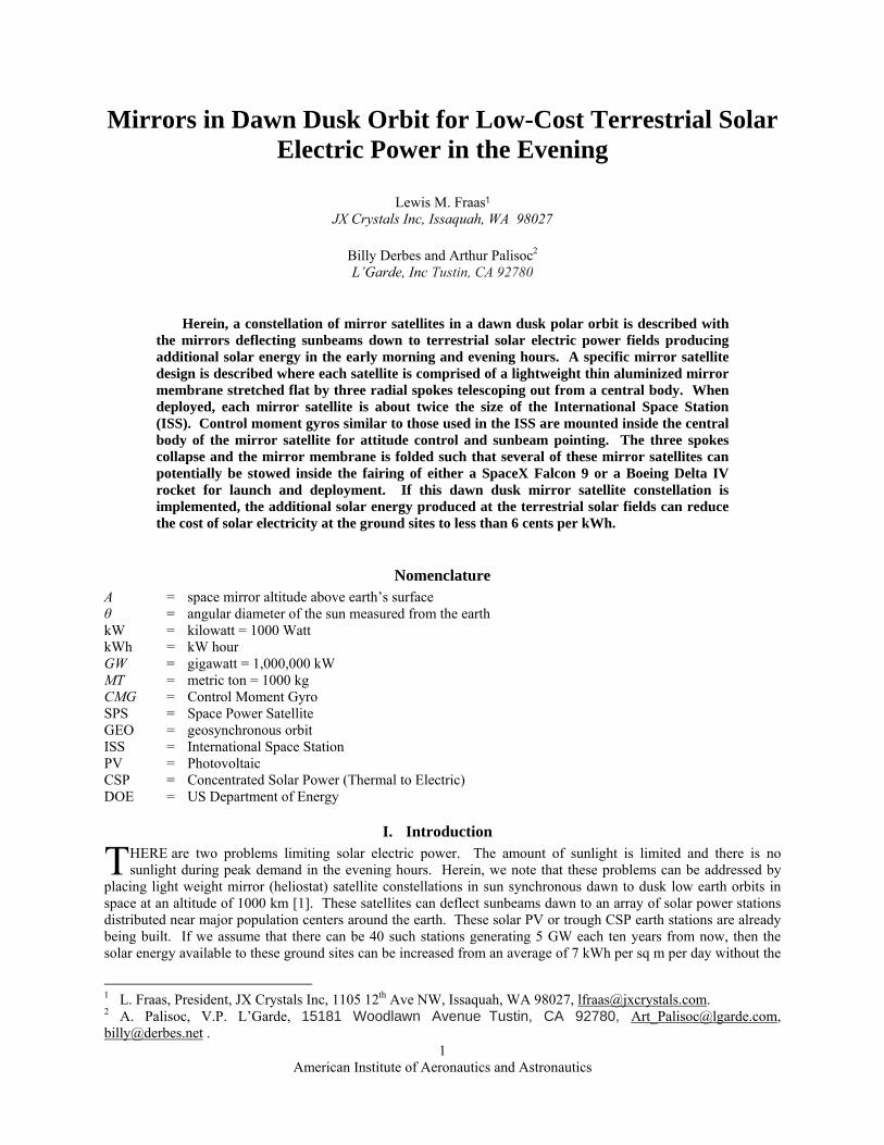
space mirrors to 12 kWh per sq m per day with the space mirrors. The additional 5 kWh per sq m per day will be provided in the early morning and evening hours. See Fig. 1. The additional solar energy can reduce the cost of solar electricity at the ground sites to less than 6 cents per kWh. We shall explore this big and challenging idea here.
0
2
4
6
8
10
12
1 3 5 7 9 11 13 15 17 19 21 23
Time Figure 1: Deflected sun beams from mirrors in sun synchronous dawn to dust low earth orbit can provide additional solar energy in early morning and evenings to ground solar electric power stations reducing the
cost of solar electricity to < 6 cents per kWh.
II. Background The idea of using mirrors in space to beam sunlight down to earth for terrestrial solar electric power generation
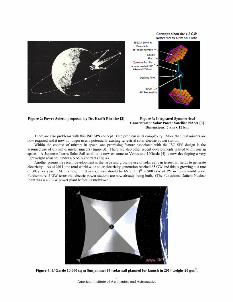
is not new. Dr. Krafft Ehricke first proposed this idea in 1978 as shown in figure 2 under the title Power Soletta [2]. Because of the simplicity of mirrors compared to the complexity of the Space Power Satellite concept, his idea was brilliant particularly for the time in which it was first proposed.
Specifically, Ehricke proposed a constellation of satellites in an orbit 4200 km in altitude beaming power down to a 1200 sq km site in Western Europe. Deflecting sunlight down to earth where it is then converted to electricity is conceptually much simpler than converting it to electricity in space and then microwave beaming it down to earth and then converting it to electricity as per the Solar Power Satellite [3] concept (figure 3).
The key physical limitation for this concept relates to the size of the sun’s disc as viewed from earth. The sun’s disc subtends an angle, θ, of 10 mrads. This means that the minimum size of a sun spot produced on the earth’s surface from a mirror in space at an altitude, A, is:
2A tan (θ/2) (1)
Applying this formula for a mirror in orbit at an altitude of 4200 km gives a sun spot diameter on earth of 42 km with a corresponding area of 1385 sq km. This explains the 1200 sq km solar field size for the Power Soletta concept. This also means that in order to produce an intensity of sunlight on earth equivalent to the normal daylight sun intensity, the area of the 3 mirrors shown beaming power down in Fig. 2 would have to be 1385 sq km and the area of the 10 mirror satellites in the constellation in Fig. 2 would have to be 4617 sq km. Unfortunately, the enormous task of placing this mirror area in orbit was somewhat discouraging in 1978.
In addition, there are two other problems with this concept as Ehricke proposed it. One problem is that this orbit falls in the Van Allen radiation belt. A second problem will reside with the size of the earth solar electric power field and the resulting problem of then distributing the power produced throughout Europe. Ehricke assumed that the 1200 sq km solar field would produce electricity at 15% efficiency implying a 180 GW central power station which then implies enormous distribution problems.
While this Power Soletta concept was intriguing, given the problems just described, NASA has focused much more attention over the subsequent years on the Space Power Satellite (SPS) concept. A recent version (2003) of this SPS concept is shown in Fig. 3. This Integrated Symmetrical Concentrator (ISC SPS) concept [3] is of interest here because it also utilizes mirrors. As shown in Fig. 3, in this concept, two sets of 36 mirrors with each mirror approximately 0.5 km in diameter are used to beam sunlight to a central PV converter platform that then generates electricity and beams microwave energy to an earth generating station. This satellite is assumed to be located in Geosynchronous Orbit at an altitude of approximately 36,000 km. The special 8 km diameter earth receiver / generator station is assumed to generate 1.2 GW of electricity.
Space Mirrors Normal Sunlight
Pow
er
American Institute of Aeronautics and Astronautics
3
Figure 2: Power Soletta proposed by Dr. Krafft Ehricke [2]
Figure 3: Integrated Symmetrical
Concentrator Solar Power Satellite NASA [3]. Dimensions: 5 km x 15 km.
There are also problems with this ISC SPS concept. One problem is its complexity. More than just mirrors are
now required and it now no longer uses a potentially existing terrestrial solar electric power station. Within the context of mirrors in space, one promising feature associated with the ISC SPS design is the
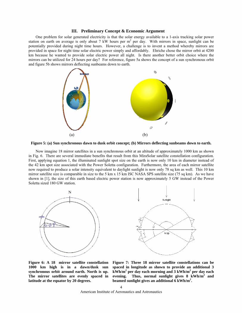
assumed use of 0.5 km diameter mirrors (figure 3). There are also other recent developments related to mirrors in space. A Japanese Ikaros Solar Sail satellite is now en route to Venus and L’Garde [4] is now developing a very lightweight solar sail under a NASA contract (Fig. 4).
Another promising recent development is the large and growing use of solar cells in terrestrial fields to generate electricity. As of 2011, the total world wide solar electricity generation reached 65 GW and this is growing at a rate of 30% per year. At this rate, in 10 years, there should be 65 x (1.3)10 = 900 GW of PV in fields world wide. Furthermore, 5 GW terrestrial electric power stations are now already being built. (The Fukushima Daiichi Nuclear Plant was a 4.7 GW power plant before its meltdown.)
Figure 4: L’Garde 10,000 sq m Sunjammer [4] solar sail planned for launch in 2014 weighs 20 g/m2.
American Institute of Aeronautics and Astronautics
4
III. Preliminary Concept & Economic Argument One problem for solar generated electricity is that the solar energy available to a 1-axis tracking solar power
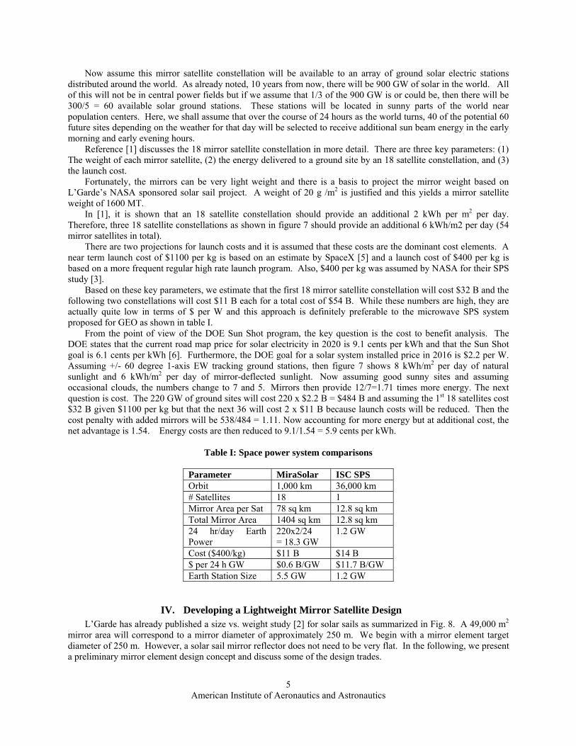
station on earth on average is only about 7 kW hours per m2 per day. With mirrors in space, sunlight can be potentially provided during night time hours. However, a challenge is to invent a method whereby mirrors are provided in space for night time solar electric power simply and affordably. Ehriche chose the mirror orbit at 4200 km because he wanted to provide solar electric power all night. Is there another better orbit choice where the mirrors can be utilized for 24 hours per day? For reference, figure 5a shows the concept of a sun synchronous orbit and figure 5b shows mirrors deflecting sunbeams down to earth.
(a) (b)
Figure 5: (a) Sun synchronous dawn to dusk orbit concept; (b) Mirrors deflecting sunbeams down to earth.
Now imagine 18 mirror satellites in a sun synchronous orbit at an altitude of approximately 1000 km as shown
in Fig. 6. There are several immediate benefits that result from this MiraSolar satellite constellation configuration. First, applying equation 1, the illuminated sunlight spot size on the earth is now only 10 km in diameter instead of the 42 km spot size associated with the Power Soletta configuration. Furthermore, the area of each mirror satellite now required to produce a solar intensity equivalent to daylight sunlight is now only 78 sq km as well. This 10 km mirror satellite size is comparable in size to the 5 km x 15 km ISC NASA SPS satellite size (75 sq km). As we have shown in [1], the size of this earth based electric power station is now approximately 5 GW instead of the Power Soletta sized 180 GW station.
N
Figure 6: A 18 mirror satellite constellation 1000 km high is in a dawn/dusk sun synchronous orbit around earth. North is up. The mirror satellites are evenly spaced in latitude at the equator by 20 degrees.
Figure 7: Three 18 mirror satellite constellations can be spaced in longitude as shown to provide an additional 3 kWh/m2 per day each morning and 3 kWh/m2 per day each evening. Thus, normal sunlight gives 8 kWh/m2 and beamed sunlight gives an additional 6 kWh/m2.
American Institute of Aeronautics and Astronautics
5
Now assume this mirror satellite constellation will be available to an array of ground solar electric stations distributed around the world. As already noted, 10 years from now, there will be 900 GW of solar in the world. All of this will not be in central power fields but if we assume that 1/3 of the 900 GW is or could be, then there will be 300/5 = 60 available solar ground stations. These stations will be located in sunny parts of the world near population centers. Here, we shall assume that over the course of 24 hours as the world turns, 40 of the potential 60 future sites depending on the weather for that day will be selected to receive additional sun beam energy in the early morning and early evening hours.
Reference [1] discusses the 18 mirror satellite constellation in more detail. There are three key parameters: (1) The weight of each mirror satellite, (2) the energy delivered to a ground site by an 18 satellite constellation, and (3) the launch cost.
Fortunately, the mirrors can be very light weight and there is a basis to project the mirror weight based on L’Garde’s NASA sponsored solar sail project. A weight of 20 g /m2 is justified and this yields a mirror satellite weight of 1600 MT.
In [1], it is shown that an 18 satellite constellation should provide an additional 2 kWh per m2 per day. Therefore, three 18 satellite constellations as shown in figure 7 should provide an additional 6 kWh/m2 per day (54 mirror satellites in total).
There are two projections for launch costs and it is assumed that these costs are the dominant cost elements. A near term launch cost of $1100 per kg is based on an estimate by SpaceX [5] and a launch cost of $400 per kg is based on a more frequent regular high rate launch program. Also, $400 per kg was assumed by NASA for their SPS study [3].
Based on these key parameters, we estimate that the first 18 mirror satellite constellation will cost $32 B and the following two constellations will cost $11 B each for a total cost of $54 B. While these numbers are high, they are actually quite low in terms of $ per W and this approach is definitely preferable to the microwave SPS system proposed for GEO as shown in table I.
From the point of view of the DOE Sun Shot program, the key question is the cost to benefit analysis. The DOE states that the current road map price for solar electricity in 2020 is 9.1 cents per kWh and that the Sun Shot goal is 6.1 cents per kWh [6]. Furthermore, the DOE goal for a solar system installed price in 2016 is $2.2 per W. Assuming +/- 60 degree 1-axis EW tracking ground stations, then figure 7 shows 8 kWh/m2 per day of natural sunlight and 6 kWh/m2 per day of mirror-deflected sunlight. Now assuming good sunny sites and assuming occasional clouds, the numbers change to 7 and 5. Mirrors then provide 12/7=1.71 times more energy. The next question is cost. The 220 GW of ground sites will cost 220 x $2.2 B = $484 B and assuming the 1st 18 satellites cost $32 B given $1100 per kg but that the next 36 will cost 2 x $11 B because launch costs will be reduced. Then the cost penalty with added mirrors will be 538/484 = 1.11. Now accounting for more energy but at additional cost, the net advantage is 1.54. Energy costs are then reduced to 9.1/1.54 = 5.9 cents per kWh.
Table I: Space power system comparisons
Parameter MiraSolar ISC SPS Orbit 1,000 km 36,000 km # Satellites 18 1 Mirror Area per Sat 78 sq km 12.8 sq km Total Mirror Area 1404 sq km 12.8 sq km 24 hr/day Earth Power
220x2/24 = 18.3 GW
1.2 GW
Cost ($400/kg) $11 B $14 B $ per 24 h GW $0.6 B/GW $11.7 B/GW Earth Station Size 5.5 GW 1.2 GW
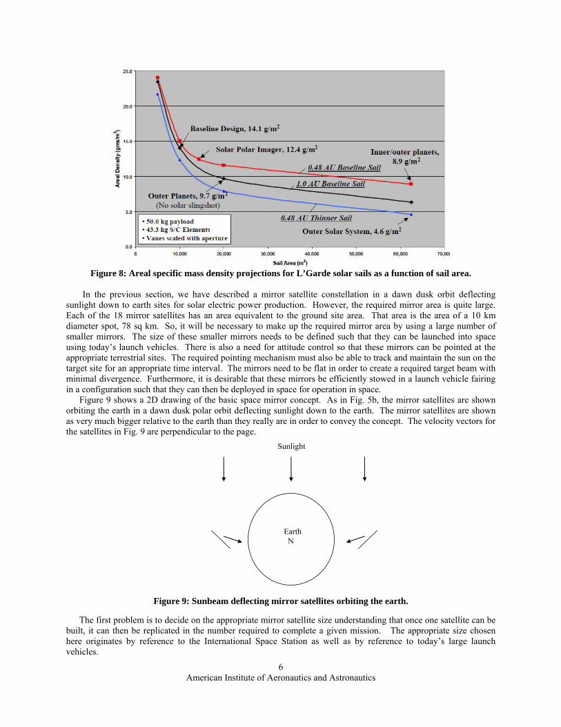
IV. Developing a Lightweight Mirror Satellite Design L’Garde has already published a size vs. weight study [2] for solar sails as summarized in Fig. 8. A 49,000 m2
mirror area will correspond to a mirror diameter of approximately 250 m. We begin with a mirror element target diameter of 250 m. However, a solar sail mirror reflector does not need to be very flat. In the following, we present a preliminary mirror element design concept and discuss some of the design trades.
American Institute of Aeronautics and Astronautics
6
Figure 8: Areal specific mass density projections for L’Garde solar sails as a function of sail area.
In the previous section, we have described a mirror satellite constellation in a dawn dusk orbit deflecting
sunlight down to earth sites for solar electric power production. However, the required mirror area is quite large. Each of the 18 mirror satellites has an area equivalent to the ground site area. That area is the area of a 10 km diameter spot, 78 sq km. So, it will be necessary to make up the required mirror area by using a large number of smaller mirrors. The size of these smaller mirrors needs to be defined such that they can be launched into space using today’s launch vehicles. There is also a need for attitude control so that these mirrors can be pointed at the appropriate terrestrial sites. The required pointing mechanism must also be able to track and maintain the sun on the target site for an appropriate time interval. The mirrors need to be flat in order to create a required target beam with minimal divergence. Furthermore, it is desirable that these mirrors be efficiently stowed in a launch vehicle fairing in a configuration such that they can then be deployed in space for operation in space. Figure 9 shows a 2D drawing of the basic space mirror concept. As in Fig. 5b, the mirror satellites are shown orbiting the earth in a dawn dusk polar orbit deflecting sunlight down to the earth. The mirror satellites are shown as very much bigger relative to the earth than they really are in order to convey the concept. The velocity vectors for the satellites in Fig. 9 are perpendicular to the page.
Sunlight
Earth N
Figure 9: Sunbeam deflecting mirror satellites orbiting the earth.
The first problem is to decide on the appropriate mirror satellite size understanding that once one satellite can be built, it can then be replicated in the number required to complete a given mission. The appropriate size chosen here originates by reference to the International Space Station as well as by reference to today’s large launch vehicles.
American Institute of Aeronautics and Astronautics
7
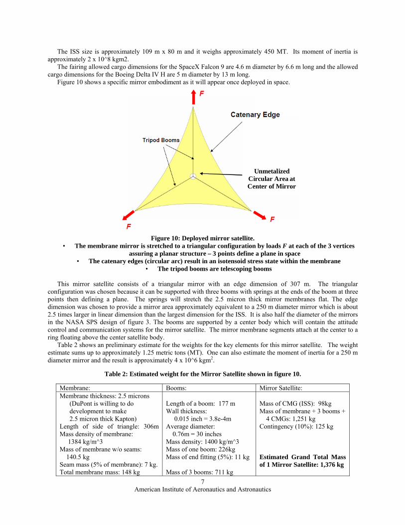
The ISS size is approximately 109 m x 80 m and it weighs approximately 450 MT. Its moment of inertia is approximately 2 x 10^8 kgm2. The fairing allowed cargo dimensions for the SpaceX Falcon 9 are 4.6 m diameter by 6.6 m long and the allowed cargo dimensions for the Boeing Delta IV H are 5 m diameter by 13 m long. Figure 10 shows a specific mirror embodiment as it will appear once deployed in space.
Unmetalized Circular Area at Center of Mirror
Figure 10: Deployed mirror satellite.
• The membrane mirror is stretched to a triangular configuration by loads F at each of the 3 vertices assuring a planar structure – 3 points define a plane in space
• The catenary edges (circular arc) result in an isotensoid stress state within the membrane • The tripod booms are telescoping booms
This mirror satellite consists of a triangular mirror with an edge dimension of 307 m. The triangular configuration was chosen because it can be supported with three booms with springs at the ends of the boom at three points then defining a plane. The springs will stretch the 2.5 micron thick mirror membranes flat. The edge dimension was chosen to provide a mirror area approximately equivalent to a 250 m diameter mirror which is about 2.5 times larger in linear dimension than the largest dimension for the ISS. It is also half the diameter of the mirrors in the NASA SPS design of figure 3. The booms are supported by a center body which will contain the attitude control and communication systems for the mirror satellite. The mirror membrane segments attach at the center to a ring floating above the center satellite body. Table 2 shows an preliminary estimate for the weights for the key elements for this mirror satellite. The weight estimate sums up to approximately 1.25 metric tons (MT). One can also estimate the moment of inertia for a 250 m diameter mirror and the result is approximately 4 x 10^6 kgm2.
Table 2: Estimated weight for the Mirror Satellite shown in figure 10.
Membrane: Booms: Mirror Satellite: Membrane thickness: 2.5 microns (DuPont is willing to do development to make 2.5 micron thick Kapton) Length of side of triangle: 306m Mass density of membrane: 1384 kg/m^3 Mass of membrane w/o seams: 140.5 kg Seam mass (5% of membrane): 7 kg. Total membrane mass: 148 kg
Length of a boom: 177 m Wall thickness: 0.015 inch = 3.8e-4m Average diameter: 0.76m = 30 inches Mass density: 1400 kg/m^3 Mass of one boom: 226kg Mass of end fitting (5%): 11 kg Mass of 3 booms: 711 kg
Mass of CMG (ISS): 98kg Mass of membrane + 3 booms + 4 CMGs: 1,251 kg Contingency (10%): 125 kg Estimated Grand Total Mass of 1 Mirror Satellite: 1,376 kg
American Institute of Aeronautics and Astronautics
8
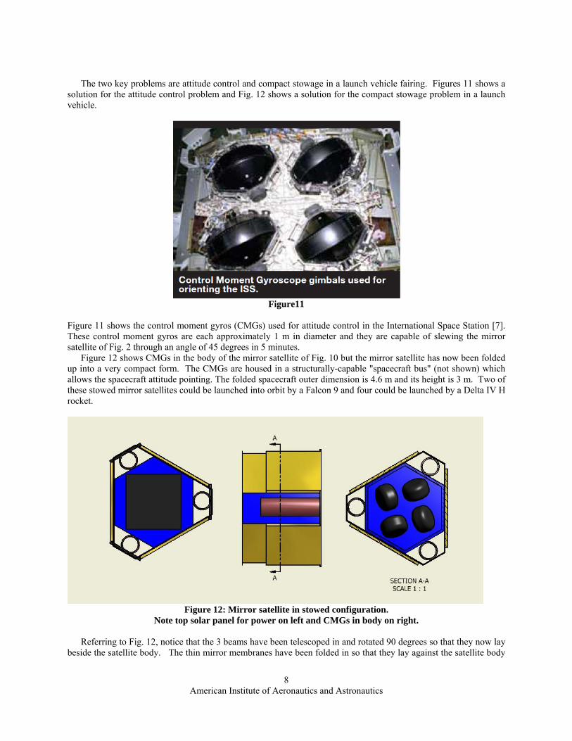
The two key problems are attitude control and compact stowage in a launch vehicle fairing. Figures 11 shows a solution for the attitude control problem and Fig. 12 shows a solution for the compact stowage problem in a launch vehicle.
Figure11
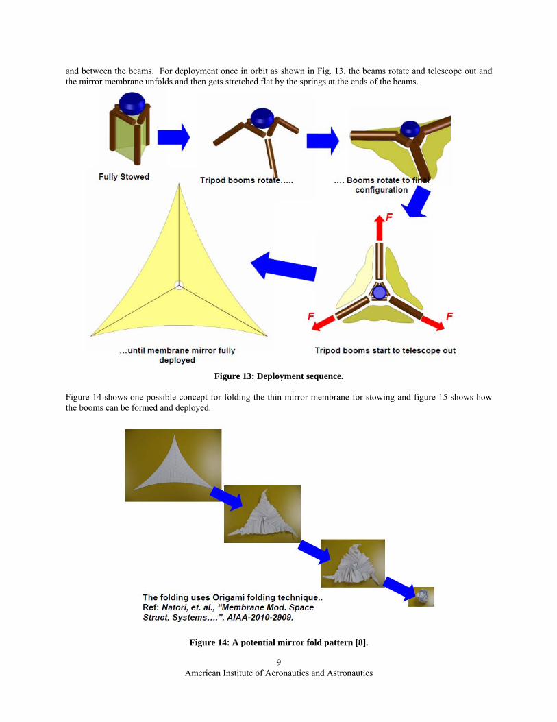
Figure 11 shows the control moment gyros (CMGs) used for attitude control in the International Space Station [7]. These control moment gyros are each approximately 1 m in diameter and they are capable of slewing the mirror satellite of Fig. 2 through an angle of 45 degrees in 5 minutes. Figure 12 shows CMGs in the body of the mirror satellite of Fig. 10 but the mirror satellite has now been folded up into a very compact form. The CMGs are housed in a structurally-capable "spacecraft bus" (not shown) which allows the spacecraft attitude pointing. The folded spacecraft outer dimension is 4.6 m and its height is 3 m. Two of these stowed mirror satellites could be launched into orbit by a Falcon 9 and four could be launched by a Delta IV H rocket.
Figure 12: Mirror satellite in stowed configuration.
Note top solar panel for power on left and CMGs in body on right.
Referring to Fig. 12, notice that the 3 beams have been telescoped in and rotated 90 degrees so that they now lay beside the satellite body. The thin mirror membranes have been folded in so that they lay against the satellite body
American Institute of Aeronautics and Astronautics
9
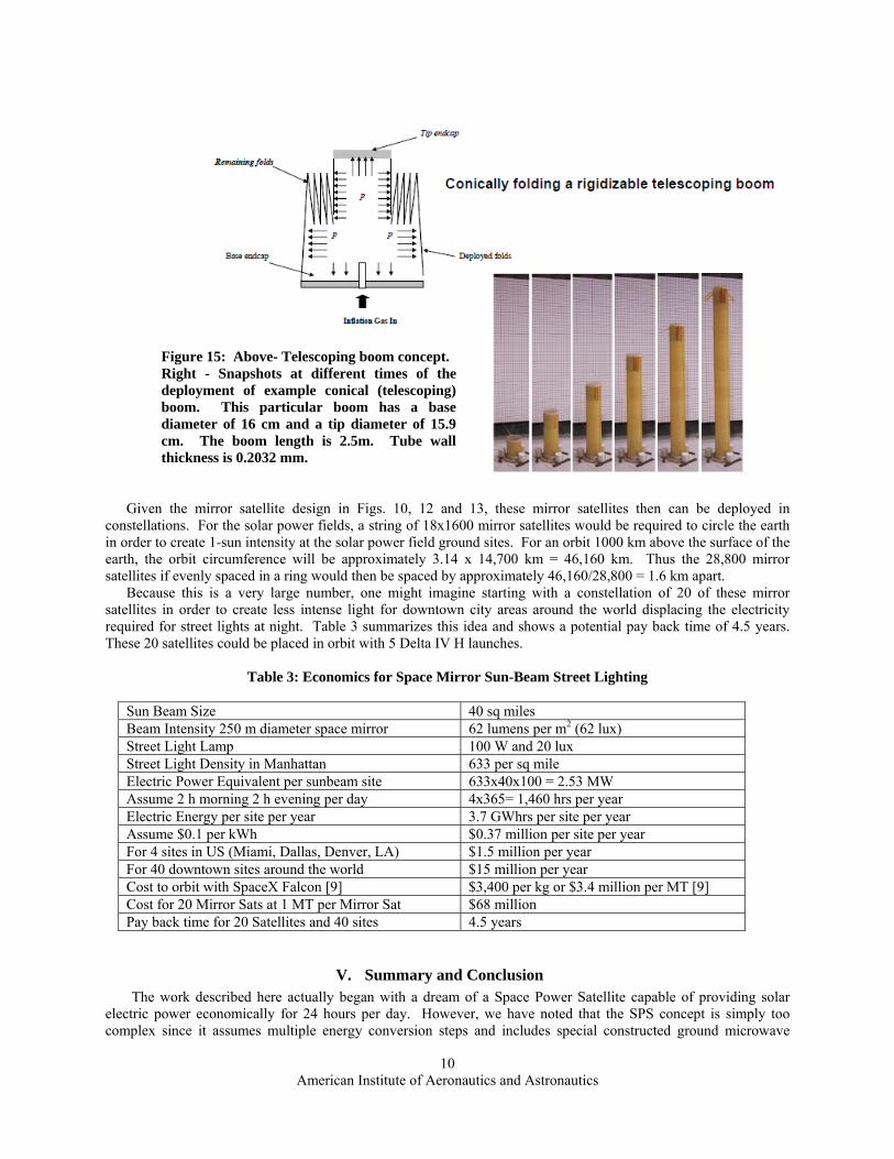
and between the beams. For deployment once in orbit as shown in Fig. 13, the beams rotate and telescope out and the mirror membrane unfolds and then gets stretched flat by the springs at the ends of the beams.
Figure 13: Deployment sequence.
Figure 14 shows one possible concept for folding the thin mirror membrane for stowing and figure 15 shows how the booms can be formed and deployed.
Figure 14: A potential mirror fold pattern [8].
American Institute of Aeronautics and Astronautics
10
Given the mirror satellite design in Figs. 10, 12 and 13, these mirror satellites then can be deployed in constellations. For the solar power fields, a string of 18x1600 mirror satellites would be required to circle the earth in order to create 1-sun intensity at the solar power field ground sites. For an orbit 1000 km above the surface of the earth, the orbit circumference will be approximately 3.14 x 14,700 km = 46,160 km. Thus the 28,800 mirror satellites if evenly spaced in a ring would then be spaced by approximately 46,160/28,800 = 1.6 km apart. Because this is a very large number, one might imagine starting with a constellation of 20 of these mirror satellites in order to create less intense light for downtown city areas around the world displacing the electricity required for street lights at night. Table 3 summarizes this idea and shows a potential pay back time of 4.5 years. These 20 satellites could be placed in orbit with 5 Delta IV H launches.
Table 3: Economics for Space Mirror Sun-Beam Street Lighting
Sun Beam Size 40 sq miles Beam Intensity 250 m diameter space mirror 62 lumens per m2 (62 lux) Street Light Lamp 100 W and 20 lux Street Light Density in Manhattan 633 per sq mile Electric Power Equivalent per sunbeam site 633x40x100 = 2.53 MW Assume 2 h morning 2 h evening per day 4x365= 1,460 hrs per year Electric Energy per site per year 3.7 GWhrs per site per year Assume $0.1 per kWh $0.37 million per site per year For 4 sites in US (Miami, Dallas, Denver, LA) $1.5 million per year For 40 downtown sites around the world $15 million per year Cost to orbit with SpaceX Falcon [9] $3,400 per kg or $3.4 million per MT [9] Cost for 20 Mirror Sats at 1 MT per Mirror Sat $68 million Pay back time for 20 Satellites and 40 sites 4.5 years
V. Summary and Conclusion The work described here actually began with a dream of a Space Power Satellite capable of providing solar
electric power economically for 24 hours per day. However, we have noted that the SPS concept is simply too complex since it assumes multiple energy conversion steps and includes special constructed ground microwave
Figure 15: Above- Telescoping boom concept. Right - Snapshots at different times of the deployment of example conical (telescoping) boom. This particular boom has a base diameter of 16 cm and a tip diameter of 15.9 cm. The boom length is 2.5m. Tube wall thickness is 0.2032 mm.
American Institute of Aeronautics and Astronautics
11
receiver stations. We then observed that mirrors deflecting sunbeams down to earth would be a much simpler concept. We then noted that there could be a surprising convergence of two technologies under development, i.e. lower cost access to space and the ongoing construction of larger and larger solar power fields around the world. Further analysis of mirrors in space in a dawn dusk orbit combined with future solar power fields has shown this idea to be actually a potentially viable economical proposition. The projected cost of this proposition of $11 billion actually appears to be comparable to the projected cost of the SPS concept at $14 billion while producing an order of magnitude more solar energy (Table 1). However, while this idea is very intriguing, the magnitude of its implementation is daunting. Nevertheless, the idea is intriguing enough to proceed with a first order design for the required mirror satellites. A mirror satellite design has been presented here. It builds from mirror technology for solar sails at L’Garde as well as technology developed for the International Space Station. It appears that the technology is available to implement this mirror satellite design and at least go to a detailed design and test stage. Furthermore, we observe that there is a smaller less expensive ($68 million) initial practical application for these mirror satellites in providing nighttime illumination for inner cites avoiding the need for electric power for street lights in the early morning and evening hours. Given all of the above, there is still another non-technical difference between the dawn dusk space mirror concept and the initial SPS concept and that difference is in perspective. The dawn dusk space mirror concept requires a global perspective and international cooperation whereas the SPS concept is based on a traditional national perspective. In this regard, the International Space Station does provide hope for future international cooperation. In the end, the concepts presented here do contribute to the dream for economical renewable energy for the world in the future. However, as is already the case, the completion of this dream is more of a political problem than a technical problem and will require leadership and vision as was demonstrated by President John F. Kennedy when he launched the Apollo Program.
References
[1] L. M. Fraas, “Mirrors in Space for Low Cost Terrestrial Solar Electric Power at Night”, Photovoltaic Specialists Conference (PVSC), 2012 38th IEEE (June 3-8 2012). www.jxcrystals.com. http://jxcrystals.com/publications/PVSC_38_Manuscript_Fraas_5-9-12.pdf
[2] K. A. Ehricke, The Extraterrestrial Imperative www.airpower.maxwell.af.mil/airchronicles/aureview/.../ehricke.html
[3] H Feingold & C Carrington, 2002, "Evaluation and Comparison of Space Solar Power Concepts" 53rd International Astronautical Congress
[4] http://www.lgarde.com/papers/2003-4659.pdf [5] Elon Musk, "Space Shuttle and the Future of Space Launch Vehicles," Senate Committee on Commerce,
Science, and Transportation, May 5, 2004. [6] http://www1.eere.energy.gov/solar/pdfs/csp_sunshot_2011march_ramamoorthy.pdf, Slide 26 [7] INTERNATIONAL SPACE STATION - NASA
www.nasa.gov/pdf/508318main_ISS_ref_guide_nov2010.pdf [8] Natori, et. al., “Membrane Mod. Space Struct. Systems….”, AIAA-2010-2909. [9] http://en.wikipedia.org/wiki/Comparison_of_orbital_launch_systems