Geometric Perturbations and Asymmetric Vortex Shedding about … · 2016-10-12 ·...
13
AIAA-2000-4103-CP Geometric Perturbations and Asymmetric Vortex Shedding about Slender Pointed Bodies Scott M. Murman ELORET Moffett Field, CA 94035 [email protected] Abstract The flow about slender, pointed bodies can be characterized by different states with angle of at- tack. At moderate-to-high angles of attack (α ≈ 40 ◦ ), a steady, asymmetric vortex pattern devel- ops along the body, leading to a net lateral force. At higher angles of attack (α ≈ 60 ◦ ), the aft-end of the body develops an unsteady von K´ arm´an shedding. As the angle of attack approaches 90 ◦ , the entire body length exhibits a time-dependent vortex shedding pattern. The current work uses three-dimensional, thin-layer Navier-Stokes sim- ulations to investigate the physical mechanisms of asymmetric vortex shedding at α = 40 ◦ and α = 60 ◦ . The development of an asymmetric vortex pattern via a convective instability mech- anism is investigated using tip bumps, surface roughness, and tip curvature. It’s found that sur- face roughness simulations can incite an asym- metric vortex state at α = 60 ◦ which is consis- tent with the application of a tip bump, and the experimentally observed flowfield. The unsteady von K´ arm´an vortex shedding on the aft portion of the body is also well resolved. The use of sur- face roughness did not incite a flow asymmetry at α = 40 ◦ , and it was necessary to simulate tip curvature at this angle of attack in order to gen- erate an asymmetric vortex state. 1 Introduction It is well known that the wake behind a cylin- drical body aligned perpendicular to the oncom- ing flow can develop an alternating pattern of strong vortices. This alternate shedding of vor- tices from the body results in an instantaneously asymmetric flowfield, while in the mean ∗ the flowfield remains symmetric. The alternate shed- Copyright c 2000 by the American Institute of Aero- nautics and Astronautics, Inc. No copyright is asserted in the United States under Title 17, U. S. Code. The U. S. Government has a royalty-free license to exercise all rights under the copyright claimed herein for Governmen- tal purposes. All other rights are reserved by the copy- right owner. ∗ mean in this work refers to time-averaging. ding of vortices from a circular cylinder is com- monly referred to as von K´ arm´an vortex shed- ding, or a von K´ arm´an vortex street. If a slen- der, pointed body of circular cross-section, such as a cone-cylinder or ogive cylinder, is placed at an angle of attack relative to the oncoming flow, it’s possible to observe a steady asymmetric flow state relative to the lateral symmetry plane of the body. This introduces the counter-intuitive notion that a nominally axisymmetric body can develop an asymmetric flow, not just instanta- neously as in the flow about a circular cylinder in crossflow, but in a time-averaged sense † . The flow about a pointed, slender body of revolution at angle of attack can thus be bro- ken down into several (experimentally-observed) [2–9] regimes (cf. Fig. 1.). The angles-of-attack where these flow regimes transition is dependent upon a number of factors, including body geom- etry, Mach number, Reynolds number, etc. At relatively low angles of attack, roughly α ≤ 20 ◦ , the flowfield remains symmetric with respect to the lateral symmetry plane of the body, even if the flow is perturbed slightly. The flow in this regime may remain attached, or boundary layer crossflow separation can occur if the angle of at- tack is sufficient, leading to a pair of vortices on the leeward side of the body which are symmet- ric relative to the lateral symmetry plane. At the opposite angle of attack extreme, 70 ◦ <α ≤ 90 ◦ (again approximately), the flow about the length of the body exhibits von K´ arm´an vortex shed- ding. In between these extremes, it’s possible for a nominally symmetric body of revolution to de- velop a non-zero mean lateral force. In the low- moderate angle-of-attack range, 20 ◦ <α ≤ 40 ◦ , the variation of mean lateral force with roll an- gle forms a continuous periodic curve. In this regime, as the angle of attack is increased, the maximum absolute value of the lateral force also increases. As the angle of attack is increased into the moderate-high range, 40 ◦ <α ≤ 70 ◦ , † It is also possible for a nominally symmetric body to exhibit a steady asymmetric flow state in crossflow due to an asymmetric boundary layer transition to turbu- lence(cf. [1]), however the current work is only concerned with asymmetric vortex states. 1
Transcript of Geometric Perturbations and Asymmetric Vortex Shedding about … · 2016-10-12 ·...
AIAA-2000-4103-CP
Geometric Perturbations and Asymmetric Vortex Sheddingabout Slender Pointed Bodies
Scott M. MurmanELORET
Moffett Field, CA [email protected]
Abstract
The flow about slender, pointed bodies can becharacterized by different states with angle of at-tack. At moderate-to-high angles of attack (α ≈40◦), a steady, asymmetric vortex pattern devel-ops along the body, leading to a net lateral force.At higher angles of attack (α ≈ 60◦), the aft-endof the body develops an unsteady von Karmanshedding. As the angle of attack approaches 90◦,the entire body length exhibits a time-dependentvortex shedding pattern. The current work usesthree-dimensional, thin-layer Navier-Stokes sim-ulations to investigate the physical mechanismsof asymmetric vortex shedding at α = 40◦ andα = 60◦. The development of an asymmetricvortex pattern via a convective instability mech-anism is investigated using tip bumps, surfaceroughness, and tip curvature. It’s found that sur-face roughness simulations can incite an asym-metric vortex state at α = 60◦ which is consis-tent with the application of a tip bump, and theexperimentally observed flowfield. The unsteadyvon Karman vortex shedding on the aft portionof the body is also well resolved. The use of sur-face roughness did not incite a flow asymmetryat α = 40◦, and it was necessary to simulate tipcurvature at this angle of attack in order to gen-erate an asymmetric vortex state.
1 Introduction
It is well known that the wake behind a cylin-drical body aligned perpendicular to the oncom-ing flow can develop an alternating pattern ofstrong vortices. This alternate shedding of vor-tices from the body results in an instantaneouslyasymmetric flowfield, while in the mean∗ theflowfield remains symmetric. The alternate shed-
Copyright c©2000 by the American Institute of Aero-nautics and Astronautics, Inc. No copyright is assertedin the United States under Title 17, U. S. Code. TheU. S. Government has a royalty-free license to exercise allrights under the copyright claimed herein for Governmen-tal purposes. All other rights are reserved by the copy-right owner.
∗mean in this work refers to time-averaging.
ding of vortices from a circular cylinder is com-monly referred to as von Karman vortex shed-ding, or a von Karman vortex street. If a slen-der, pointed body of circular cross-section, suchas a cone-cylinder or ogive cylinder, is placed atan angle of attack relative to the oncoming flow,it’s possible to observe a steady asymmetric flowstate relative to the lateral symmetry plane ofthe body. This introduces the counter-intuitivenotion that a nominally axisymmetric body candevelop an asymmetric flow, not just instanta-neously as in the flow about a circular cylinderin crossflow, but in a time-averaged sense†.
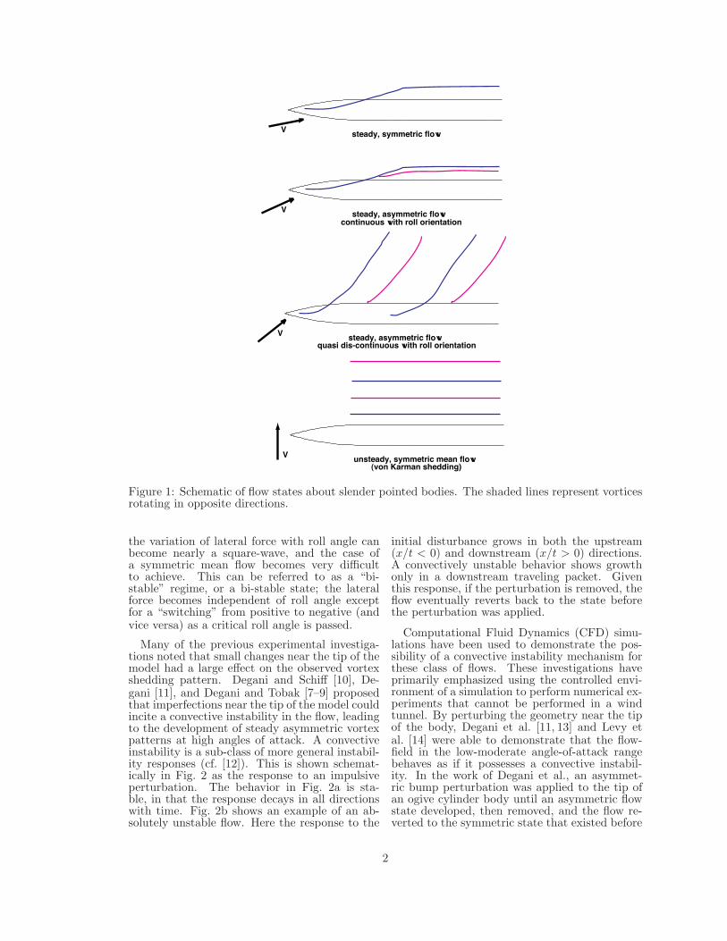
The flow about a pointed, slender body ofrevolution at angle of attack can thus be bro-ken down into several (experimentally-observed)[2–9] regimes (cf. Fig. 1.). The angles-of-attackwhere these flow regimes transition is dependentupon a number of factors, including body geom-etry, Mach number, Reynolds number, etc. Atrelatively low angles of attack, roughly α ≤ 20◦,the flowfield remains symmetric with respect tothe lateral symmetry plane of the body, even ifthe flow is perturbed slightly. The flow in thisregime may remain attached, or boundary layercrossflow separation can occur if the angle of at-tack is sufficient, leading to a pair of vortices onthe leeward side of the body which are symmet-ric relative to the lateral symmetry plane. At theopposite angle of attack extreme, 70◦ < α ≤ 90◦(again approximately), the flow about the lengthof the body exhibits von Karman vortex shed-ding. In between these extremes, it’s possible fora nominally symmetric body of revolution to de-velop a non-zero mean lateral force. In the low-moderate angle-of-attack range, 20◦ < α ≤ 40◦,the variation of mean lateral force with roll an-gle forms a continuous periodic curve. In thisregime, as the angle of attack is increased, themaximum absolute value of the lateral force alsoincreases. As the angle of attack is increasedinto the moderate-high range, 40◦ < α ≤ 70◦,
†It is also possible for a nominally symmetric bodyto exhibit a steady asymmetric flow state in crossflowdue to an asymmetric boundary layer transition to turbu-lence(cf. [1]), however the current work is only concernedwith asymmetric vortex states.
1
V steady, symmetric flow
V steady, asymmetric flowcontinuous with roll orientation
V steady, asymmetric flowquasi dis-continuous with roll orientation
V unsteady, symmetric mean flow(von Karman shedding)
Figure 1: Schematic of flow states about slender pointed bodies. The shaded lines represent vorticesrotating in opposite directions.
the variation of lateral force with roll angle canbecome nearly a square-wave, and the case ofa symmetric mean flow becomes very difficultto achieve. This can be referred to as a “bi-stable” regime, or a bi-stable state; the lateralforce becomes independent of roll angle exceptfor a “switching” from positive to negative (andvice versa) as a critical roll angle is passed.
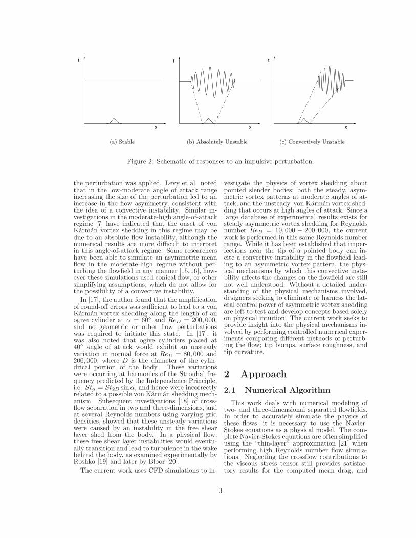
Many of the previous experimental investiga-tions noted that small changes near the tip of themodel had a large effect on the observed vortexshedding pattern. Degani and Schiff [10], De-gani [11], and Degani and Tobak [7–9] proposedthat imperfections near the tip of the model couldincite a convective instability in the flow, leadingto the development of steady asymmetric vortexpatterns at high angles of attack. A convectiveinstability is a sub-class of more general instabil-ity responses (cf. [12]). This is shown schemat-ically in Fig. 2 as the response to an impulsiveperturbation. The behavior in Fig. 2a is sta-ble, in that the response decays in all directionswith time. Fig. 2b shows an example of an ab-solutely unstable flow. Here the response to the
initial disturbance grows in both the upstream(x/t < 0) and downstream (x/t > 0) directions.A convectively unstable behavior shows growthonly in a downstream traveling packet. Giventhis response, if the perturbation is removed, theflow eventually reverts back to the state beforethe perturbation was applied.
Computational Fluid Dynamics (CFD) simu-lations have been used to demonstrate the pos-sibility of a convective instability mechanism forthese class of flows. These investigations haveprimarily emphasized using the controlled envi-ronment of a simulation to perform numerical ex-periments that cannot be performed in a windtunnel. By perturbing the geometry near the tipof the body, Degani et al. [11, 13] and Levy etal. [14] were able to demonstrate that the flow-field in the low-moderate angle-of-attack rangebehaves as if it possesses a convective instabil-ity. In the work of Degani et al., an asymmet-ric bump perturbation was applied to the tip ofan ogive cylinder body until an asymmetric flowstate developed, then removed, and the flow re-verted to the symmetric state that existed before
2
x
t
(a) Stable
x
t
(b) Absolutely Unstable
x
t
(c) Convectively Unstable
Figure 2: Schematic of responses to an impulsive perturbation.
the perturbation was applied. Levy et al. notedthat in the low-moderate angle of attack rangeincreasing the size of the perturbation led to anincrease in the flow asymmetry, consistent withthe idea of a convective instability. Similar in-vestigations in the moderate-high angle-of-attackregime [7] have indicated that the onset of vonKarman vortex shedding in this regime may bedue to an absolute flow instability, although thenumerical results are more difficult to interpretin this angle-of-attack regime. Some researchershave been able to simulate an asymmetric meanflow in the moderate-high regime without per-turbing the flowfield in any manner [15,16], how-ever these simulations used conical flow, or othersimplifying assumptions, which do not allow forthe possibility of a convective instability.
In [17], the author found that the amplificationof round-off errors was sufficient to lead to a vonKarman vortex shedding along the length of anogive cylinder at α = 60◦ and ReD = 200, 000,and no geometric or other flow perturbationswas required to initiate this state. In [17], itwas also noted that ogive cylinders placed at40◦ angle of attack would exhibit an unsteadyvariation in normal force at ReD = 80, 000 and200, 000, where D is the diameter of the cylin-drical portion of the body. These variationswere occurring at harmonics of the Strouhal fre-quency predicted by the Independence Principle,i.e. Stα = St2D sinα, and hence were incorrectlyrelated to a possible von Karman shedding mech-anism. Subsequent investigations [18] of cross-flow separation in two and three-dimensions, andat several Reynolds numbers using varying griddensities, showed that these unsteady variationswere caused by an instability in the free shearlayer shed from the body. In a physical flow,these free shear layer instabilities would eventu-ally transition and lead to turbulence in the wakebehind the body, as examined experimentally byRoshko [19] and later by Bloor [20].
The current work uses CFD simulations to in-
vestigate the physics of vortex shedding aboutpointed slender bodies; both the steady, asym-metric vortex patterns at moderate angles of at-tack, and the unsteady, von Karman vortex shed-ding that occurs at high angles of attack. Since alarge database of experimental results exists forsteady asymmetric vortex shedding for Reynoldsnumber ReD = 10, 000 − 200, 000, the currentwork is performed in this same Reynolds numberrange. While it has been established that imper-fections near the tip of a pointed body can in-cite a convective instability in the flowfield lead-ing to an asymmetric vortex pattern, the phys-ical mechanisms by which this convective insta-bility affects the changes on the flowfield are stillnot well understood. Without a detailed under-standing of the physical mechanisms involved,designers seeking to eliminate or harness the lat-eral control power of asymmetric vortex sheddingare left to test and develop concepts based solelyon physical intuition. The current work seeks toprovide insight into the physical mechanisms in-volved by performing controlled numerical exper-iments comparing different methods of perturb-ing the flow; tip bumps, surface roughness, andtip curvature.
2 Approach
2.1 Numerical Algorithm
This work deals with numerical modeling oftwo- and three-dimensional separated flowfields.In order to accurately simulate the physics ofthese flows, it is necessary to use the Navier-Stokes equations as a physical model. The com-plete Navier-Stokes equations are often simplifiedusing the “thin-layer” approximation [21] whenperforming high Reynolds number flow simula-tions. Neglecting the crossflow contributions tothe viscous stress tensor still provides satisfac-tory results for the computed mean drag, and
3
von Karman shedding frequency at the flow con-ditions of interest in this work (cf. [18]), and allof the simulations in the current work utilize thissimplification to reduce the computational costs.At the Reynolds number considered in the cur-rent work, the boundary layer remains laminar,and a numerical turbulence model is not required.
In order to accurately resolve the viscous stressterms, a fine grid spacing is required in each co-ordinate direction that the viscous stresses can-not be neglected. This grid spacing makes theuse of implicit methods desirable when usingfinite-difference algorithms because of the stiff-ness of the Navier-Stokes equations. The im-plicit schemes used in this work are all based onperforming a time-linearization of the non-linearflux vectors, and obtaining a so-called “delta for-mulation” of the governing equations [22]. Thebackward Euler implicit time-integration schemeis used throughout. This is a first-order accuratescheme in time, however the allowable numericaltime-step due to stability considerations for theseflows is much smaller than required to resolve thephysics of the unsteady von Karman shedding,and a first-order scheme has been found to pro-vide satisfactory results (cf. [17, 18]).
In order to numerically integrate the govern-ing equations, the spatial derivatives must bereplaced by suitable finite-difference formulas.A straight-forward approach is to replace theinviscid derivatives with second-order, central-difference operators, and the viscous derivativeswith centered, second-order mid-point operators.Unfortunately, this produces a scheme which ismoderately unstable in three dimensions [23].This weak instability can be overcome howeverwith the addition of numerical dissipation ofan order that doesn’t interfere with the accu-racy of any physical mechanisms. The explicitdissipation is scaled by the local flow proper-ties to reduce it’s influence within the boundarylayer, where the natural viscous dissipation of theNavier-Stokes equations is suitable.
This combination of central-differenced spa-tial terms and higher-order numerical dissipationleads to what is referred to here as a block formof the Beam and Warming algorithm [22, 23].The block formulation is preferred over the diag-onalized algorithm of Pulliam and Chausee [24]due to an inherent asymmetry of the diagonal-ization process that can lead to spurious flowasymmetries for high-angle-of-attack simulations(cf. [25]).
2.2 Computational Grids
Computations were performed about atangent-ogive cylinder configuration with a 3.5diameter forebody attached to a 7.0 diame-ter cylindrical aft section. This is the sameconfiguration examined computationally byDegani et al. [7–9, 11], in previous work by the
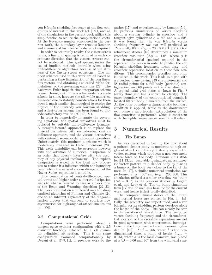
author [17], and experimentally by Lamont [5,6].In previous simulations of vortex sheddingabout a circular cylinder in crossflow and atangent-ogive cylinder at α = 60◦ and α = 80◦,it was found that the von Karman vortexshedding frequency was not well predicted atReD = 80, 000 or ReD = 200, 000 (cf. [17]). Gridrefinement studies [18] determined a minimumcrossflow resolution (∆φ = 1.0◦, where φ isthe circumferential spacing) required in theseparated flow region in order to predict the vonKarman shedding frequency, mean drag, andcrossflow separation location at these flow con-ditions. This recommended crossflow resolutionis utilized in this work. This leads to a grid witha crossflow plane having 249 circumferential and58 radial points for a full-body (periodic) con-figuration, and 69 points in the axial direction.A typical axial grid plane is shown in Fig. 3(every third grid line is shown for clarity). Theouter boundary of the computational domain islocated fifteen body diameters from the surface.At the outer boundary a characteristic boundarycondition is applied, while at the downstreamexit plane a zeroth-order extrapolation of theflow quantities is performed, which is consistentwith the highly convective nature of the flowfield.
3 Numerical Results
3.1 Tip Bump
As was described in Sec. 1, the flow abouta pointed slender body at moderate-to-high an-gles of attack can develop a steady asymmetricvortex pattern which produces a non-zero meanlateral force on the body. Previous CFD stud-ies [11,13,14], were able to simulate an asymmet-ric vortex pattern on a slender body by placinga bump on the body very close to the tip of thenose. In [17], a similar numerical simulation wasperformed at α = 60◦ and ReD = 200, 000. Thissimulation utilized a similar crossflow resolution(∆φ = 3.0◦) as the previous studies by Deganiet al. and Levy et al. The tip-bump simulationfrom [17] will be used as a baseline for the currentwork, and hence is first briefly described.
The computed time-histories of the lateraland normal forces are plotted in Fig. 4. Ini-tially, the geometry was unperturbed, and a vonKarman vortex shedding pattern develops alongthe length of the body. This can clearly be seenin the variation of lateral force. The computedvortex shedding frequency and the circumferen-tial location of the crossflow separation are notin good agreement with experimental investiga-tions of shedding from a two-dimensional cylin-der (cf. [18]). At t = 266, where t is the non-dimensional time, a bump of height hmax =0.01d, where d is the local diameter, was placedat x/D = 0.06 and 90◦ from the windward sym-
4
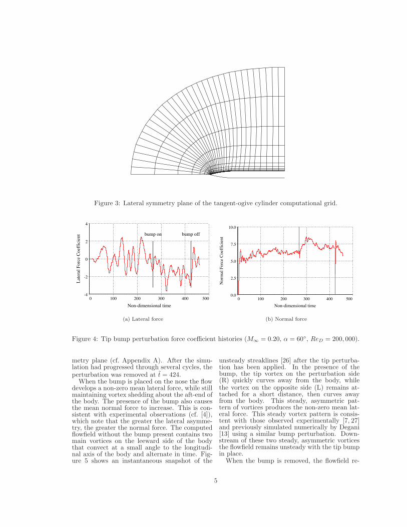
Figure 3: Lateral symmetry plane of the tangent-ogive cylinder computational grid.
0 100 200 300 400 500
bump on bump off
Non-dimensional time
-4
-2
0
2
4
Lat
eral
For
ce C
oeff
icie
nt
(a) Lateral force
0 100 200 300 400 500
Non-dimensional time
0.0
2.5
5.0
7.5
10.0
Nor
mal
For
ce C
oeff
icie
nt
(b) Normal force
Figure 4: Tip bump perturbation force coefficient histories (M∞ = 0.20, α = 60◦, ReD = 200, 000).
metry plane (cf. Appendix A). After the simu-lation had progressed through several cycles, theperturbation was removed at t = 424.
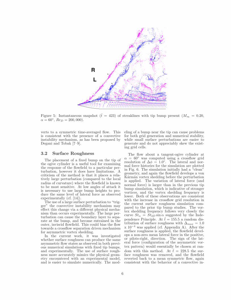
When the bump is placed on the nose the flowdevelops a non-zero mean lateral force, while stillmaintaining vortex shedding about the aft-end ofthe body. The presence of the bump also causesthe mean normal force to increase. This is con-sistent with experimental observations (cf. [4]),which note that the greater the lateral asymme-try, the greater the normal force. The computedflowfield without the bump present contains twomain vortices on the leeward side of the bodythat convect at a small angle to the longitudi-nal axis of the body and alternate in time. Fig-ure 5 shows an instantaneous snapshot of the
unsteady streaklines [26] after the tip perturba-tion has been applied. In the presence of thebump, the tip vortex on the perturbation side(R) quickly curves away from the body, whilethe vortex on the opposite side (L) remains at-tached for a short distance, then curves awayfrom the body. This steady, asymmetric pat-tern of vortices produces the non-zero mean lat-eral force. This steady vortex pattern is consis-tent with those observed experimentally [7, 27]and previously simulated numerically by Degani[13] using a similar bump perturbation. Down-stream of these two steady, asymmetric vorticesthe flowfield remains unsteady with the tip bumpin place.
When the bump is removed, the flowfield re-
5
R
L
Figure 5: Instantaneous snapshot (t = 423) of streaklines with tip bump present (M∞ = 0.20,α = 60◦, ReD = 200, 000).
verts to a symmetric time-averaged flow. Thisis consistent with the presence of a convectiveinstability mechanism, as has been proposed byDegani and Tobak [7–9].
3.2 Surface Roughness
The placement of a fixed bump on the tip ofthe ogive cylinder is a useful tool for examiningthe response of the flowfield to a particular per-turbation, however it does have limitations. Acriticism of the method is that it places a rela-tively large perturbation (compared to the localradius of curvature) where the flowfield is knownto be most sensitive. At low angles of attack itis necessary to use large bump heights to pro-duce the same level of lateral force as observedexperimentally (cf. [14]).
The use of a large surface perturbation to “trig-ger” the convective instability mechanism mayeffect this change via a different physical mecha-nism than occurs experimentally. The large per-turbation can cause the boundary layer to sepa-rate at the bump, and become entrained in theouter, inviscid flowfield. This could bias the flowtowards a crossflow separation driven mechanismfor asymmetric vortex shedding.
In the current work, it was investigatedwhether surface roughness can produce the sameasymmetric flow states as observed in both previ-ous numerical simulations with fixed tip bumps,and experimentally. The use of surface rough-ness more accurately mimics the physical geom-etry encountered with an experimental model,and is easier to simulate numerically. The mod-
eling of a bump near the tip can cause problemsfor both grid generation and numerical stability,while small surface perturbations are easier togenerate and do not appreciably skew the exist-ing grid cells.
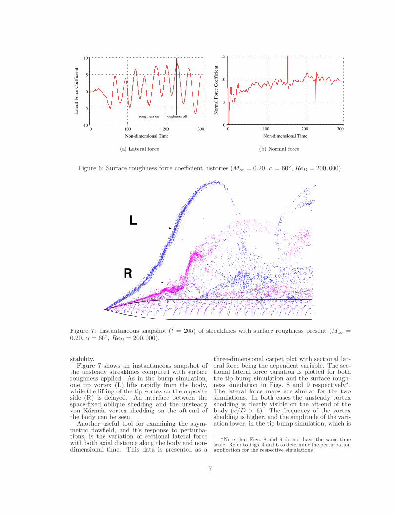
The flow about a tangent-ogive cylinder atα = 60◦ was computed using a crossflow gridresolution of ∆φ = 1.0◦. The lateral and nor-mal force histories for the simulation are plottedin Fig. 6. The simulation initially had a “clean”geometry, and again the flowfield develops a vonKarman vortex shedding before the perturbationis applied. The variation of lateral force (andnormal force) is larger than in the previous tipbump simulation, which is indicative of strongervortices, and the vortex shedding frequency islower. Both of these observations are consistentwith the increase in crossflow grid resolution inthe current surface roughness simulation com-pared to the prior tip bump studies. The vor-tex shedding frequency follows very closely thecurve Stα = St2D sin α suggested by the Inde-pendence Principle. At t = 155.5 a random dis-tribution of surface roughness with ∆max = 1.0x 10⁻⁴ was applied (cf. Appendix A). After thesurface roughness is applied, the flowfield devel-ops a non-zero mean lateral force in the positive,or pilots-right, direction. The sign of the lat-eral force (configuration of the asymmetric vor-tex pattern) would essentially be chosen at ran-dom with this method. At t = 228.5 the sur-face roughness was removed, and the flowfieldreverted back to a mean symmetric flow, againconsistent with the behavior of a convective in-
6
0 100 200 300
Non-dimensional Time
-10
-5
0
5
10
Lat
eral
For
ce C
oeff
icie
nt
roughness on roughness off
(a) Lateral force
0 100 200 300
Non-dimensional Time
0
5
10
15
Nor
mal
For
ce C
oeff
icie
nt
(b) Normal force
Figure 6: Surface roughness force coefficient histories (M∞ = 0.20, α = 60◦, ReD = 200, 000).
R
L
Figure 7: Instantaneous snapshot (t = 205) of streaklines with surface roughness present (M∞ =0.20, α = 60◦, ReD = 200, 000).
stability.Figure 7 shows an instantaneous snapshot of
the unsteady streaklines computed with surfaceroughness applied. As in the bump simulation,one tip vortex (L) lifts rapidly from the body,while the lifting of the tip vortex on the oppositeside (R) is delayed. An interface between thespace-fixed oblique shedding and the unsteadyvon Karman vortex shedding on the aft-end ofthe body can be seen.
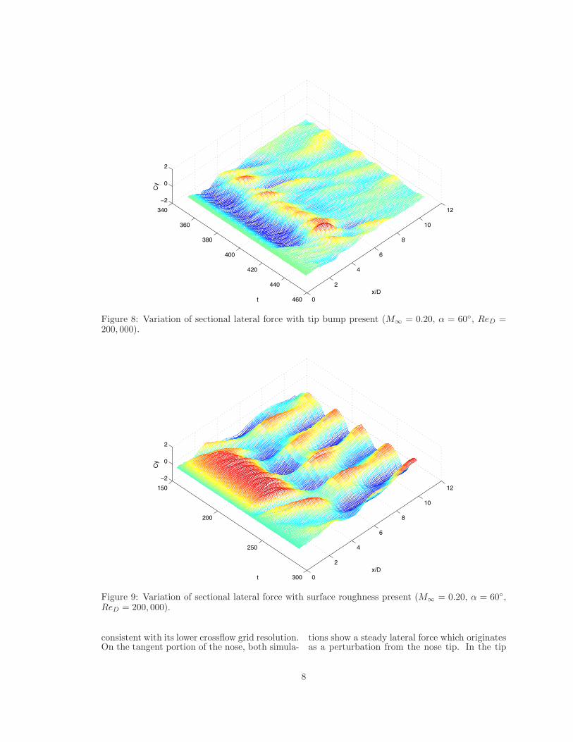
Another useful tool for examining the asym-metric flowfield, and it’s response to perturba-tions, is the variation of sectional lateral forcewith both axial distance along the body and non-dimensional time. This data is presented as a
three-dimensional carpet plot with sectional lat-eral force being the dependent variable. The sec-tional lateral force variation is plotted for boththe tip bump simulation and the surface rough-ness simulation in Figs. 8 and 9 respectively∗.The lateral force maps are similar for the twosimulations. In both cases the unsteady vortexshedding is clearly visible on the aft-end of thebody (x/D > 6). The frequency of the vortexshedding is higher, and the amplitude of the vari-ation lower, in the tip bump simulation, which is
∗Note that Figs. 8 and 9 do not have the same timescale. Refer to Figs. 4 and 6 to determine the perturbationapplication for the respective simulations.
7
340
360
380
400
420
440
460 0
2
4
6
8
10
12
−2
0
2
x/Dt
Cy
Figure 8: Variation of sectional lateral force with tip bump present (M∞ = 0.20, α = 60◦, ReD =200, 000).
150
200
250
300 0
2
4
6
8
10
12
−2
0
2
x/Dt
Cy
Figure 9: Variation of sectional lateral force with surface roughness present (M∞ = 0.20, α = 60◦,ReD = 200, 000).
consistent with its lower crossflow grid resolution.On the tangent portion of the nose, both simula-
tions show a steady lateral force which originatesas a perturbation from the nose tip. In the tip
8
t = 354 t = 375 t = 400
Tip bump
t = 160 t = 180 t = 200
Surface Roughness
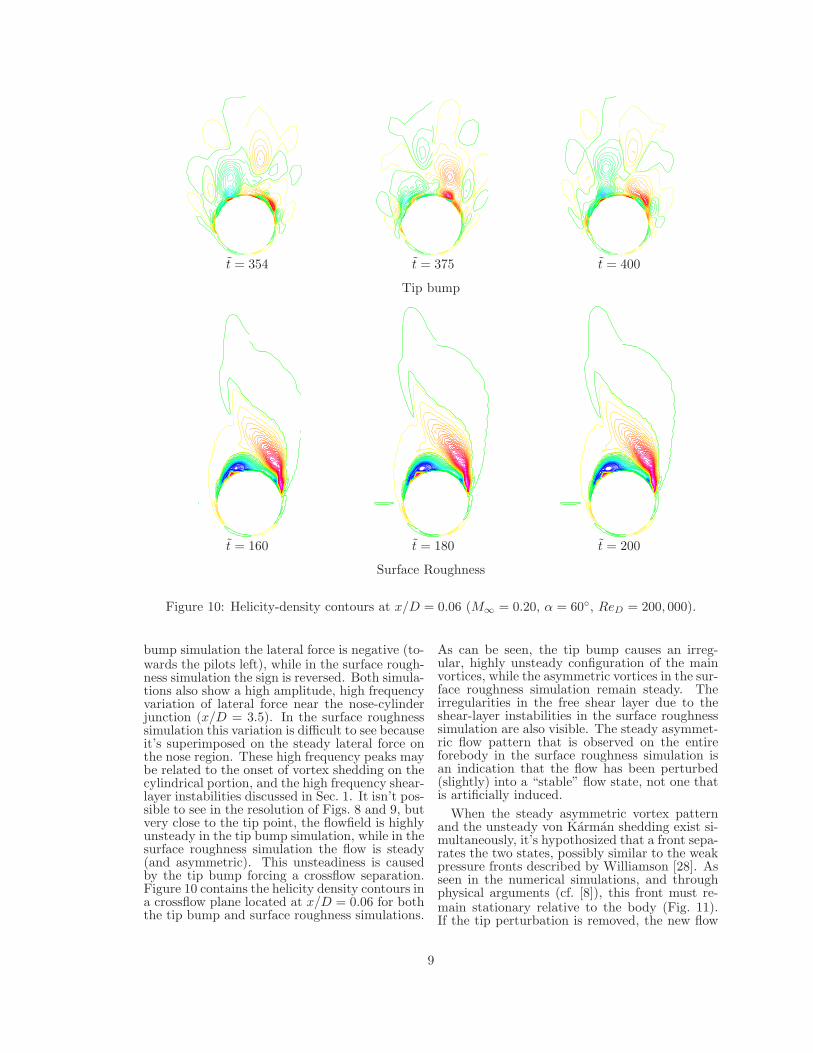
Figure 10: Helicity-density contours at x/D = 0.06 (M∞ = 0.20, α = 60◦, ReD = 200, 000).
bump simulation the lateral force is negative (to-wards the pilots left), while in the surface rough-ness simulation the sign is reversed. Both simula-tions also show a high amplitude, high frequencyvariation of lateral force near the nose-cylinderjunction (x/D = 3.5). In the surface roughnesssimulation this variation is difficult to see becauseit’s superimposed on the steady lateral force onthe nose region. These high frequency peaks maybe related to the onset of vortex shedding on thecylindrical portion, and the high frequency shear-layer instabilities discussed in Sec. 1. It isn’t pos-sible to see in the resolution of Figs. 8 and 9, butvery close to the tip point, the flowfield is highlyunsteady in the tip bump simulation, while in thesurface roughness simulation the flow is steady(and asymmetric). This unsteadiness is causedby the tip bump forcing a crossflow separation.Figure 10 contains the helicity density contours ina crossflow plane located at x/D = 0.06 for boththe tip bump and surface roughness simulations.
As can be seen, the tip bump causes an irreg-ular, highly unsteady configuration of the mainvortices, while the asymmetric vortices in the sur-face roughness simulation remain steady. Theirregularities in the free shear layer due to theshear-layer instabilities in the surface roughnesssimulation are also visible. The steady asymmet-ric flow pattern that is observed on the entireforebody in the surface roughness simulation isan indication that the flow has been perturbed(slightly) into a “stable” flow state, not one thatis artificially induced.
When the steady asymmetric vortex patternand the unsteady von Karman shedding exist si-multaneously, it’s hypothosized that a front sepa-rates the two states, possibly similar to the weakpressure fronts described by Williamson [28]. Asseen in the numerical simulations, and throughphysical arguments (cf. [8]), this front must re-main stationary relative to the body (Fig. 11).If the tip perturbation is removed, the new flow
9
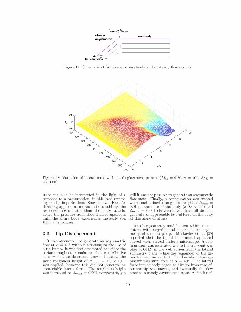
Vfront = Vbody
steady asymmetric
unsteady
tip perturbation
Figure 11: Schematic of front separating steady and unsteady flow regions.
170
180
190
200
210
220
230
240
250
260 0
2
4
6
8
10
12
−0.5
0
0.5
x/Dt
Cy
Figure 12: Variation of lateral force with tip displacement present (M∞ = 0.20, α = 40◦, ReD =200, 000).
state can also be interpreted in the light of aresponse to a perturbation, in this case remov-ing the tip imperfections. Since the von Karmanshedding appears as an absolute instability, theresponse moves faster than the body travels,hence the pressure front should move upstreamuntil the entire body experiences unsteady vonKarman shedding.
3.3 Tip Displacement
It was attempted to generate an asymmetricflow at α = 40◦ without resorting to the use ofa tip bump. It was first attempted to utilize thesurface roughness simulation that was effectiveat α = 60◦, as described above. Initially, thesame roughness height of ∆max = 1.0 x 10⁻⁴
was applied, however this did not generate anappreciable lateral force. The roughness heightwas increased to ∆max = 0.001 everywhere, yet
still it was not possible to generate an asymmetricflow state. Finally, a configuration was createdwhich maintained a roughness height of ∆max =0.01 on the nose of the body (x/D < 1.0) and∆max = 0.001 elsewhere, yet this still did notgenerate an appreciable lateral force on the bodyat this angle of attack.
Another geometry modification which is con-sistent with experimental models is an asym-metry of the sharp tip. Moskovitz et al. [29]reported that the tip of their model appearedcurved when viewed under a microscope. A con-figuration was generated where the tip point wasoffset 0.001D in the y-direction from the lateralsymmetry plane, while the remainder of the ge-ometry was unmodified. The flow about this ge-ometry was simulated at α = 40◦. The lateralforce immediately began to diverge from zero af-ter the tip was moved, and eventually the flowreached a steady asymmetric state. A similar ef-
10
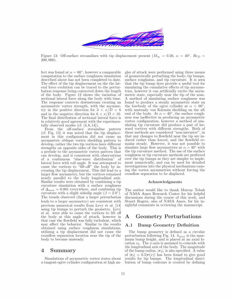
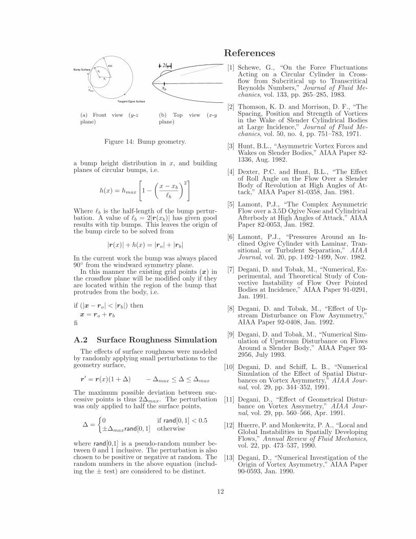
Figure 13: Off-surface streamlines with tip displacement present (M∞ = 0.20, α = 40◦, ReD =200, 000).
fect was found at α = 60◦, however a comparablecomputation to the surface roughness simulationdescribed above has not been completed to date.The effect of the tip displacement on the the lat-eral force evolution can be traced to the pertur-bation response being convected down the lengthof the body. Figure 12 shows the variation ofsectional lateral force along the body with time.The response convects downstream creating anasymmetric vortex strength, with the asymme-try in the positive direction for 3 < x/D < 6and in the negative direction for 6 < x/D < 10.The final distribution of sectional lateral force isin relatively good agreement with the experimen-tally observed modes (cf. [4, 6, 14]).
From the off-surface streamline pattern(cf. Fig. 13) it was noted that the tip displace-ment in this configuration did not cause anasymmetric oblique vortex shedding pattern todevelop, rather the two tip vortices have differentstrengths on opposite sides of the body. This isa prelude to the asymmetric vortex pattern thatcan develop, and is consistent with observationsof a continuous “sine-wave distribution” oflateral force with roll angle. It was attempted tocause the vortices to “lift-off” the body by in-creasing the tip displacement. This did lead to alarger flow asymmetry, but the vortices remainednearly parallel to the body longitudinal axis.Similar results were obtained by combining a tipcurvature simulation with a surface roughnessof ∆max = 0.001 everywhere, and combining tipcurvature with a slight sideslip angle (β = 2.0◦).The trends observed (that a larger perturbationleads to a larger asymmetry) are consistent withprevious numerical results from Levy et al. [14]using tip bumps to perturb the geometry. Levyet al. were able to cause the vortices to lift offthe body at this angle of attack, however inthat case the flowfield was fully turbulent, whichmay affect the behavior. Similar to the resultsobtained using surface roughness simulations,utilizing a tip displacement did not cause thecrossflow separation location near the tip of thebody to become unsteady.
4 Summary
Simulations of asymmetric vortex states abouta tangent-ogive cylinder configuration at high an-
gles of attack were performed using three meansof geometrically perturbing the body; tip bumps,surface roughness, and tip curvature. It is seenthat the tip bump does provide a useful tool forsimulating the cumulative effects of tip asymme-tries, however it can artificially excite the asym-metric state, especially near the tip of the nose.A method of simulating surface roughness wasfound to produce a steady asymmetric state onthe forebody of the ogive cylinder at α = 60◦,with unsteady von Karman shedding on the aftend of the body. At α = 40◦, the surface rough-ness was ineffective in producing an asymmetricvortex configuration, however a method of sim-ulating tip curvature did produce a pair of lee-ward vortices with different strengths. Both ofthese methods are considered “non-intrusive”, inthat any changes to flowfield near the tip are in-duced rather than forced, and the flowfield re-mains steady. However, it was not possible tosimulate large flow asymmetries at α = 40◦ withthe tip curvature method. The use of the surfaceroughness or tip curvature methods are preferredover the tip bumps as they are simpler to imple-ment numerically, and can be used for detailedinvestigations into the physical mechanisms caus-ing the vortex asymmetries without forcing thecrossflow separation to be displaced.
Acknowledgments
The author would like to thank Murray Tobakof NASA Ames Research Center for his helpfuldiscussions during the course of this work, andStuart Rogers, also of NASA Ames, for his in-sightful comments in reviewing the manuscript.
A Geometry Perturbations
A.1 Bump Geometry Definition
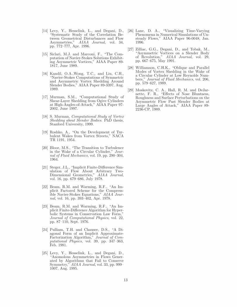
The bump geometry is defined as a circularperturbation following Fig. 14. hmax is the max-imum bump height, and is placed at an axial lo-cation xb. The x-axis is assumed to coincide withthe longitudinal axis of the body. The magnitudeof the bump radius, |rb|, is also specified. A valueof |rb| = 0.5|r(x)| has been found to give goodresults for tip bumps. The longitudinal distri-bution of bump contours is created by defining
11
r(x)
ro
rb
hmax
Tangent-Ogive Surface
Bump Surface
(a) Front view (y-zplane)
2lb
xb
(b) Top view (x-yplane)
Figure 14: Bump geometry.
a bump height distribution in x, and buildingplanes of circular bumps, i.e.
h(x) = hmax
[1 −
(x − xb
�b
)2]
Where �b is the half-length of the bump pertur-bation. A value of �b = 2|r(xb)| has given goodresults with tip bumps. This leaves the origin ofthe bump circle to be solved from
|r(x)| + h(x) = |ro| + |rb|In the current work the bump was always placed90◦ from the windward symmetry plane.
In this manner the existing grid points (x) inthe crossflow plane will be modified only if theyare located within the region of the bump thatprotrudes from the body, i.e.
if (|x − ro| < |rb|) thenx = ro + rb
fi
A.2 Surface Roughness Simulation
The effects of surface roughness were modeledby randomly applying small perturbations to thegeometry surface,
r′ = r(x)(1 + ∆) − ∆max ≤ ∆ ≤ ∆max
The maximum possible deviation between suc-cessive points is thus 2∆max. The perturbationwas only applied to half the surface points,
∆ ={
0 if rand[0, 1] < 0.5±∆maxrand[0, 1] otherwise
where rand[0,1] is a pseudo-random number be-tween 0 and 1 inclusive. The perturbation is alsochosen to be positive or negative at random. Therandom numbers in the above equation (includ-ing the ± test) are considered to be distinct.
References
[1] Schewe, G., “On the Force FluctuationsActing on a Circular Cylinder in Cross-flow from Subcritical up to TranscriticalReynolds Numbers,” Journal of Fluid Me-chanics, vol. 133, pp. 265–285, 1983.
[2] Thomson, K. D. and Morrison, D. F., “TheSpacing, Position and Strength of Vorticesin the Wake of Slender Cylindrical Bodiesat Large Incidence,” Journal of Fluid Me-chanics, vol. 50, no. 4, pp. 751–783, 1971.
[3] Hunt, B.L., “Asymmetric Vortex Forces andWakes on Slender Bodies,” AIAA Paper 82-1336, Aug. 1982.
[4] Dexter, P.C. and Hunt, B.L., “The Effectof Roll Angle on the Flow Over a SlenderBody of Revolution at High Angles of At-tack,” AIAA Paper 81-0358, Jan. 1981.
[5] Lamont, P.J., “The Complex AsymmetricFlow over a 3.5D Ogive Nose and CylindricalAfterbody at High Angles of Attack,” AIAAPaper 82-0053, Jan. 1982.
[6] Lamont, P.J., “Pressures Around an In-clined Ogive Cylinder with Laminar, Tran-sitional, or Turbulent Separation,” AIAAJournal, vol. 20, pp. 1492–1499, Nov. 1982.
[7] Degani, D. and Tobak, M., “Numerical, Ex-perimental, and Theoretical Study of Con-vective Instability of Flow Over PointedBodies at Incidence,” AIAA Paper 91-0291,Jan. 1991.
[8] Degani, D. and Tobak, M., “Effect of Up-stream Disturbance on Flow Asymmetry,”AIAA Paper 92-0408, Jan. 1992.
[9] Degani, D. and Tobak, M., “Numerical Sim-ulation of Upstream Disturbance on FlowsAround a Slender Body,” AIAA Paper 93-2956, July 1993.
[10] Degani, D. and Schiff, L. B., “NumericalSimulation of the Effect of Spatial Distur-bances on Vortex Asymmetry,” AIAA Jour-nal, vol. 29, pp. 344–352, 1991.
[11] Degani, D., “Effect of Geometrical Distur-bance on Vortex Assymetry,” AIAA Jour-nal, vol. 29, pp. 560–566, Apr. 1991.
[12] Huerre, P. and Monkewitz, P. A., “Local andGlobal Instabilities in Spatially DevelopingFlows,” Annual Review of Fluid Mechanics,vol. 22, pp. 473–537, 1990.
[13] Degani, D., “Numerical Investigation of theOrigin of Vortex Asymmetry,” AIAA Paper90-0593, Jan. 1990.
12
[14] Levy, Y., Hesselink, L., and Degani, D.,“Systematic Study of the Correlation Be-tween Geometrical Disturbances and FlowAsymmetries,” AIAA Journal, vol. 34,pp. 772–777, Apr. 1996.
[15] Siclari, M.J. and Marconi, F., “The Com-putation of Navier-Stokes Solutions Exhibit-ing Asymmetric Vortices,” AIAA Paper 89-1817, June 1989.
[16] Kandil, O.A.,Wong, T.C., and Liu, C.H.,“Navier-Stokes Computations of Symmetricand Asymmetric Vortex Shedding AroundSlender Bodies,” AIAA Paper 89-3397, Aug.1989.
[17] Murman, S.M., “Computational Study ofShear-Layer Shedding from Ogive Cylindersat High-Angles-of-Attack,” AIAA Paper 97-2002, June 1997.
[18] S. Murman, Computational Study of VortexShedding about Slender Bodies. PhD thesis,Stanford University, 1999.
[19] Roshko, A., “On the Development of Tur-bulent Wakes from Vortex Streets,” NACATR 1191, 1954.
[20] Bloor, M.S., “The Transition to Turbulencein the Wake of a Circular Cylinder,” Jour-nal of Fluid Mechanics, vol. 19, pp. 290–304,1964.
[21] Steger, J.L., “Implicit Finite-Difference Sim-ulation of Flow About Arbitrary Two-Dimensional Geometries,” AIAA Journal,vol. 16, pp. 679–686, July 1978.
[22] Beam, R.M. and Warming, R.F., “An Im-plicit Factored Scheme for the Compress-ible Navier-Stokes Equations,” AIAA Jour-nal, vol. 16, pp. 393–402, Apr. 1978.
[23] Beam, R.M. and Warming, R.F., “An Im-plicit Finite-Difference Algorithm for Hyper-bolic Systems in Conservation Law Form,”Journal of Computational Physics, vol. 22,pp. 87–110, Sept. 1976.
[24] Pulliam, T.H. and Chausee, D.S., “A Di-agonal Form of an Implicit Approximate-Factorization Algorithm,” Journal of Com-putational Physics, vol. 39, pp. 347–363,Feb. 1981.
[25] Levy, Y., Hesselink, L., and Degani, D.,“Anomolous Asymmetries in Flows Gener-ated by Algorithms that Fail to ConserveSymmetry,” AIAA Journal, vol. 33, pp. 999–1007, Aug. 1995.
[26] Lane, D. A., “Visualizing Time-VaryingPhenomena in Numerical Simulations of Un-steady Flows,” AIAA Paper 96-0048, Jan.1996.
[27] Zilliac, G.G., Degani, D., and Tobak, M.,“Asymmetric Vortices on a Slender Bodyof Revolution,” AIAA Journal, vol. 29,pp. 667–675, May 1991.
[28] Williamson, C.H.K., “Oblique and ParallelModes of Vortex Shedding in the Wake ofa Circular Cylinder at Low Reynolds Num-bers,” Journal of Fluid Mechanics, vol. 206,pp. 579–627, 1989.
[29] Moskovitz, C. A., Hall, R. M. and DeJar-nette, F. R., “Effects of Nose Bluntness,Roughness and Surface Perturbations on theAsymmetric Flow Past Slender Bodies atLarge Angles of Attack,” AIAA Paper 89-2236-CP, 1989.
13