Microwave Cavity Structures for an Axion Search R.E.U. Presentation August 13, 2012 Hunter Swan.
19
Microwave Cavity Structures for an Axion Search R.E.U. Presentation August 13, 2012 Hunter Swan
-
Upload
alondra-gedney -
Category
Documents
-
view
240 -
download
0
Transcript of Microwave Cavity Structures for an Axion Search R.E.U. Presentation August 13, 2012 Hunter Swan.
Microwave Cavity Structures for an Axion Search
R.E.U. Presentation
August 13, 2012
Hunter Swan
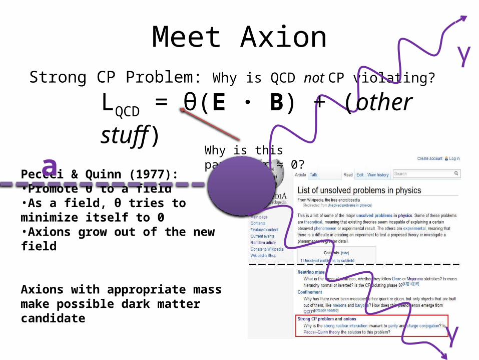
Meet AxionStrong CP Problem: Why is QCD not CP violating?
Why is this parameter ≈ 0?
Peccei & Quinn (1977):•Promote θ to a field•As a field, θ tries to minimize itself to 0•Axions grow out of the new field
Axions with appropriate mass make possible dark matter candidate
a
γ
γ
LQCD = θ(E · B) + (other stuff)
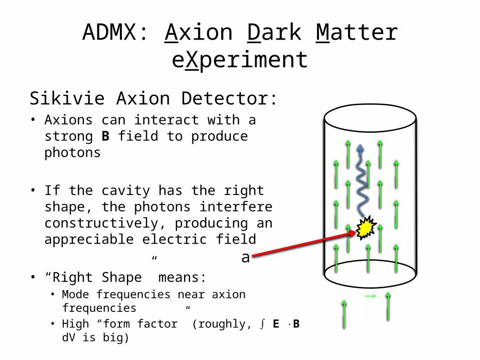
ADMX: Axion Dark Matter eXperiment
Sikivie Axion Detector:• Axions can interact with a strong B field
to produce photons
• If the cavity has the right shape, the photons interfere constructively, producing an appreciable electric field
• “Right Shape” means:• Mode frequencies near axion frequencies• High “form factor” (roughly, ∫ E B ⋅ dV is big)
a
B
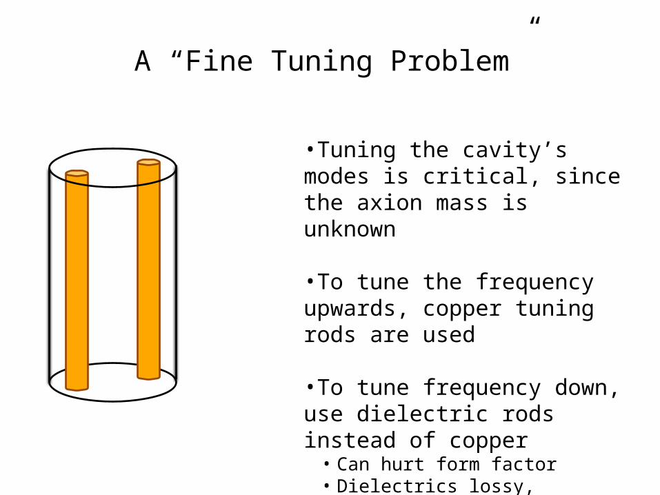
A “Fine Tuning Problem”
•Tuning the cavity’s modes is critical, since the axion mass is unknown
•To tune the frequency upwards, copper tuning rods are used
•To tune frequency down, use dielectric rods instead of copper• Can hurt form factor• Dielectrics lossy, expensive
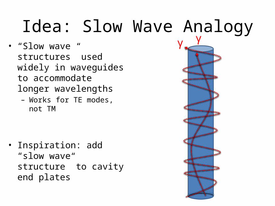
Idea: Slow Wave Analogy• “Slow wave structures” used
widely in waveguides to accommodate longer wavelengths– Works for TE modes, not TM
• Inspiration: add “slow wave structure” to cavity end plates
γ γ
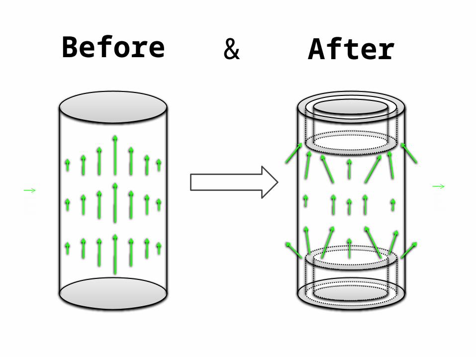
Before
E E
After&
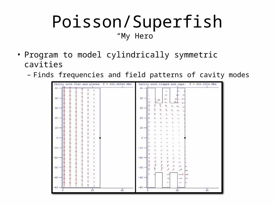
Poisson/Superfish“My Hero”
• Program to model cylindrically symmetric cavities– Finds frequencies and field patterns of cavity modes
Superfish Predicts Success
0 5 10 15 20 250
50
100
150
200
250
300
350
400
450
500
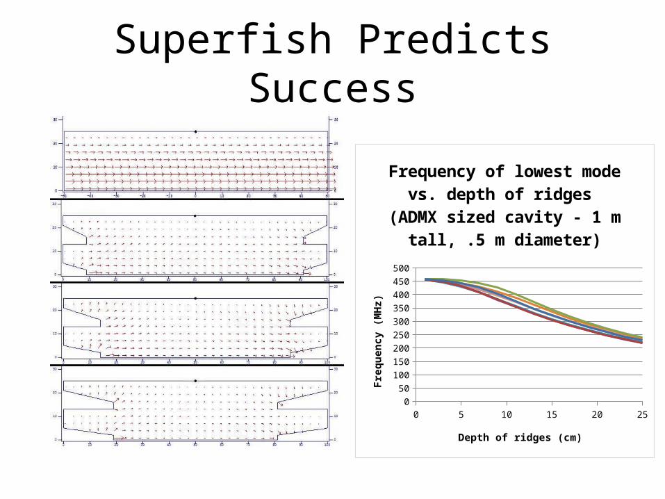
Frequency of lowest mode vs. depth of ridges
(ADMX sized cavity - 1 m tall, .5 m diameter)
Depth of ridges (cm)
Freq
uenc
y (M
Hz)
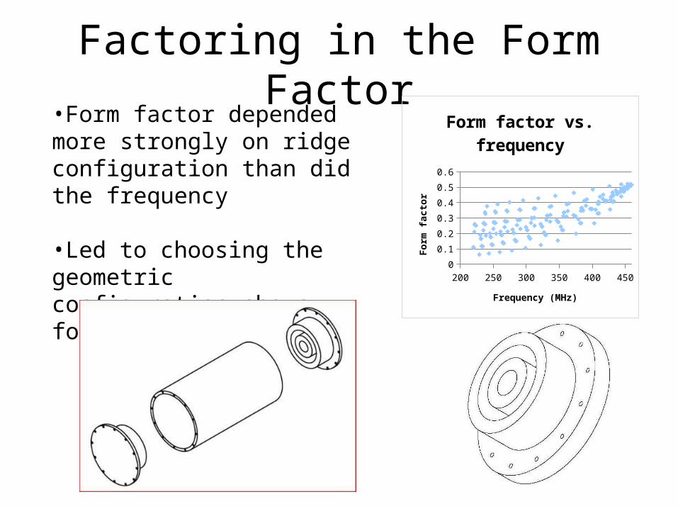
Factoring in the Form Factor
200 250 300 350 400 4500
0.1
0.2
0.3
0.4
0.5
0.6
Form factor vs. frequency
Frequency (MHz)
Form
fact
or
•Form factor depended more strongly on ridge configuration than did the frequency
•Led to choosing the geometric configuration shown for further testing
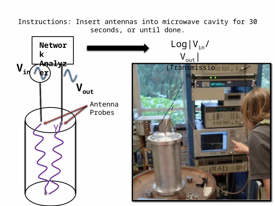
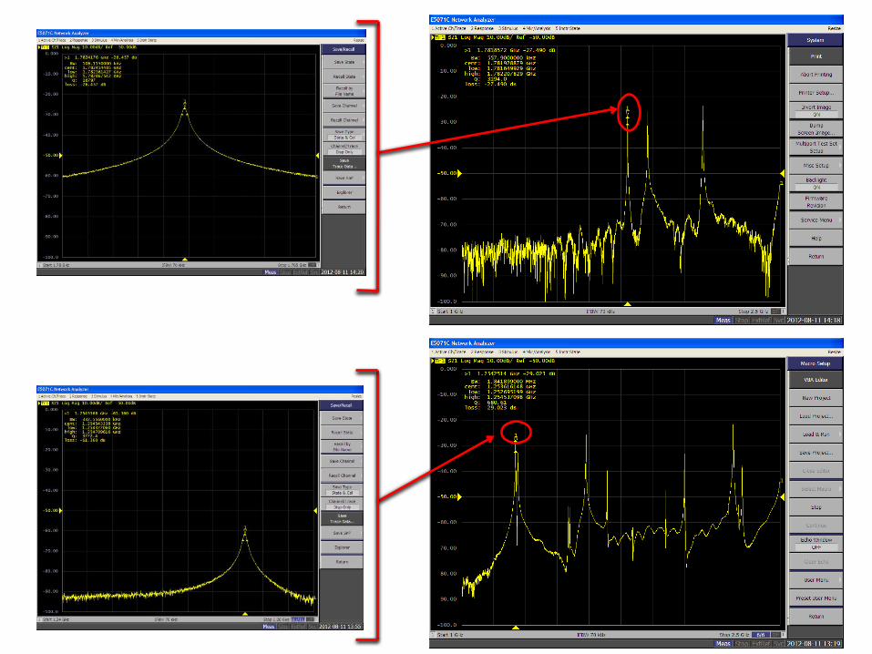
Antenna Probes
Instructions: Insert antennas into microwave cavity for 30 seconds, or until done.
Vin Vout
NetworkAnalyzer
Log|Vin/Vout|(Transmission)
γ
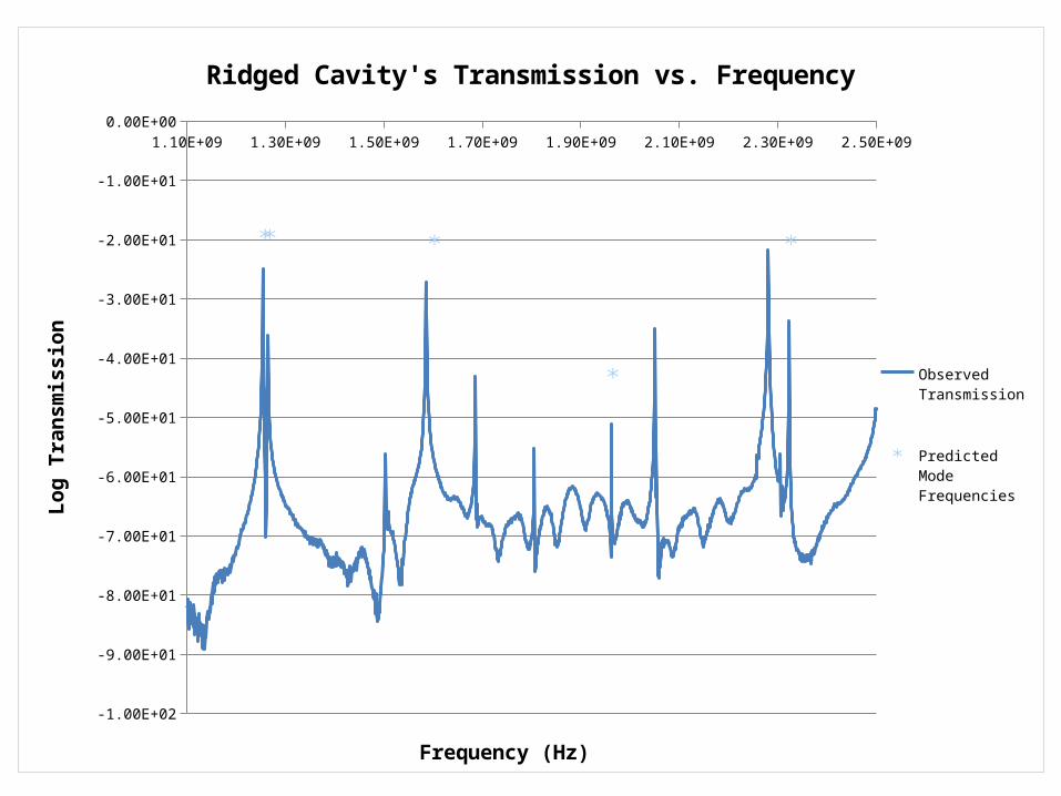
1.10E+09 1.30E+09 1.50E+09 1.70E+09 1.90E+09 2.10E+09 2.30E+09 2.50E+09
-1.00E+02
-9.00E+01
-8.00E+01
-7.00E+01
-6.00E+01
-5.00E+01
-4.00E+01
-3.00E+01
-2.00E+01
-1.00E+01
0.00E+00
Ridged Cavity's Transmission vs. Frequency
Observed Trans-mission
Predicted Mode Frequencies
Frequency (Hz)
Log
Tran
smis
sion
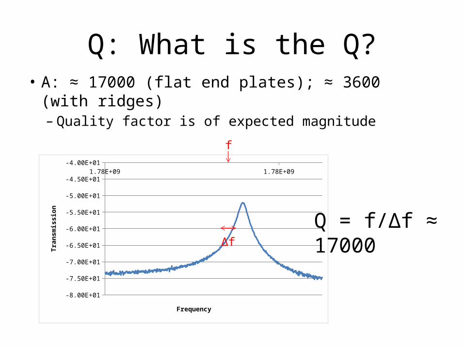
Q: What is the Q?• A: ≈ 17000 (flat end plates); ≈ 3600 (with ridges)– Quality factor is of expected magnitude
1.78E+09 1.78E+09
-8.00E+01
-7.50E+01
-7.00E+01
-6.50E+01
-6.00E+01
-5.50E+01
-5.00E+01
-4.50E+01
-4.00E+01
Frequency
Tran
smiss
ion
Δf
Q = f/Δf ≈ 17000
f
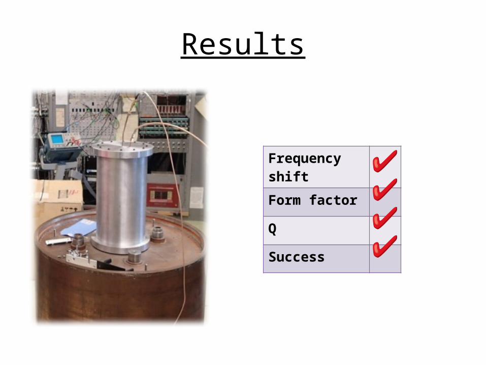
Results
Frequency shift
Form factor
Q
Success
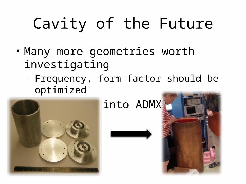
Cavity of the Future
• Many more geometries worth investigating– Frequency, form factor should be optimized
• Incorporate into ADMX?
Thanks
• Professor Rosenberg, Gray Rybka, Andrew Wagner, Christian Boutan, & Dima Lyapustin—the ADMX fellows.
• Deep Gupta, Alejandro Garcia, Janine Nemerever, & Linda Vilett—the REU folks.
• Emma, Becca, Emily, Rachel, Eli, Jarrett, & Scott—they’re cool people.
• God—your great, and you got me through this presentation.
Disclaimer
• The opinions expressed in this presentation are solely the work of those presenting them and do not necessarily reflect the views of ADMX or any of its collaborators, funding agencies, or affiliates. ADMX is not liable for any damage, injury, or ill will that may come about as a result of this presentation or any material contained therein.


![Installation Manual English - Hunter Fans Australia · Pengawatan Kanopi Bilah Rumah Sakelar Perangkat Lampu Pengoperasian Kontrol Dinding ... (contoh: [a]) mengidentifikasi ... teks.](https://static.fdocument.org/doc/165x107/5c9d0bd288c99397348c2911/installation-manual-english-hunter-fans-pengawatan-kanopi-bilah-rumah-sakelar.jpg)