Mechanical Design and Horizontal Tests of a Dressed 166.6 ...
5
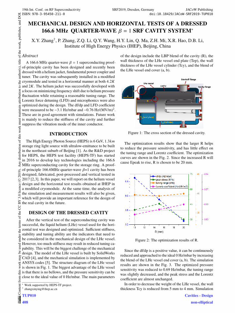
MECHANICAL DESIGN AND HORIZONTAL TESTS OF A DRESSED 166.6 QUARTER-WAVE β = 1 SRF CAVITY SYSTEM ∗ X.Y. Zhang † , P. Zhang, Z.Q. Li, Q.Y. Wang, H.Y. Lin, Q. Ma, Z.H. Mi, X.R. Hao, D.B. Li, Institute of High Energy Physics (IHEP), Beijing, China Abstract A 166.6 MHz quarter-wave β = 1 superconducting proof- of-principle cavity has been designed and recently been dressed with a helium jacket, fundamental power coupler and tuner. The cavity was subsequently installed in a modified cryomodule and tested in a horizontal manner at both 4.2K and 2K . The helium jacket was successfully developed with a focus on minimizing frequency shift due to helium pressure fluctuation while retaining a reasonable tuning range. The Lorentz force detuning (LFD) and microphonics were also optimized during the design. The df/dp and LFD coefficient were measured to be −3.1 Hz/mbar and −0.76 Hz/(MV/m) 2 . These are in good agreement with simulations. Future work is mainly to reduce the stiffness of the cavity and further suppress the vibration mode of the inner conductor. INTRODUCTION The High Energy Photon Source (HEPS) is 6 GeV, 1.3km storage ring light source with ultralow-emittance to be built in the northeast suburb of Beijing [1]. As the R&D project for HEPS, the HEPS test facility (HEPS-TF) has started in 2016 to develop key technologies including the 166.6 MHz superconducting cavity for the storage ring. A proof- of-principle 166.6MHz quarter-wave β=1 cavity has been designed, fabricated, post-processed and vertical tested in 2017 [2,3]. In this paper, we will report on the helium vessel design and the horizontal test results obtained at IHEP in a modified cryomodule. At the same time, the analysis of the simulation and measurement results will also be given, which will provide an important reference for the design of the real cavity in the future. DESIGN OF THE DRESSED CAVITY After the vertical test of the superconducting cavity was successful, the liquid helium (LHe) vessel used for the hori- zontal test was designed and optimized. Sufficient stiffness, stability and tuning ability are the indicators that need to be considered in the mechanical design of the LHe vessel. However, too much stiffness may result in reduced tuning ca- pability. This will be the biggest challenge of the mechanical design. The model of the LHe vessel is built by SolidWorks CAD [4], and the mechanical simulation is implemented by ANSYS codes [5]. The structure diagram of the LHe vessel is shown in Fig. 1. The biggest advantage of the LHe vessel is that there is no bellows, and the pressure sensitivity can be close to the ideal value of 0 Hz/mbar. The main parameters ∗ Work supported by HEPS-TF project. † [email protected] of the design include the LBP blend of the cavity (R), the wall thickness of the LHe vessel end plate (Tep), the wall thickness of the LHe vessel cylinder (Tcy), and the blend of the LHe vessel end cover (a, b). Figure 1: The cross section of the dressed cavity. The optimization results show that the larger R helps to reduce the pressure sensitivity, and has little effect on the tuning range and Lorentz coefficient. The optimization curves are shown in the Fig. 2. Since the increased R will cause Epeak to rise, R is chosen to be 20 mm. Figure 2: The optimization results of R. Since the df/dp is a positive value, it can be continuously reduced and approached to the ideal 0 Hz/mbar by increasing the blend of the LHe vessel end cover (a, b). The simulation results are shown in the Fig. 3. The optimized pressure sensitivity was reduced to 0.69 Hz/mbar, the tuning range was slightly decreased, and the peak stress and the Lorentz coefficient are almost unchanged. In order to decrease the weight of the LHe vessel, the wall thickness Tcy is reduced from 5 mm to 4 mm. Simulation MHz 19th Int. Conf. on RF Superconductivity SRF2019, Dresden, Germany JACoW Publishing ISBN: 978-3-95450-211-0 doi:10.18429/JACoW-SRF2019-TUP010 TUP010 408 Content from this work may be used under the terms of the CC BY 3.0 licence (© 2019). Any distribution of this work must maintain attribution to the author(s), title of the work, publisher, and DOI. Cavities - Design non-elliptical
Transcript of Mechanical Design and Horizontal Tests of a Dressed 166.6 ...
MECHANICAL DESIGN AND HORIZONTAL TESTS OF A DRESSED
166.6 QUARTER-WAVE β = 1 SRF CAVITY SYSTEM∗
X.Y. Zhang†, P. Zhang, Z.Q. Li, Q.Y. Wang, H.Y. Lin, Q. Ma, Z.H. Mi, X.R. Hao, D.B. Li,
Institute of High Energy Physics (IHEP), Beijing, China
Abstract
A 166.6 MHz quarter-wave β = 1 superconducting proof-
of-principle cavity has been designed and recently been
dressed with a helium jacket, fundamental power coupler and
tuner. The cavity was subsequently installed in a modified
cryomodule and tested in a horizontal manner at both 4.2K
and 2K . The helium jacket was successfully developed with
a focus on minimizing frequency shift due to helium pressure
fluctuation while retaining a reasonable tuning range. The
Lorentz force detuning (LFD) and microphonics were also
optimized during the design. The df/dp and LFD coefficient
were measured to be −3.1 Hz/mbar and −0.76 Hz/(MV/m)2.
These are in good agreement with simulations. Future work
is mainly to reduce the stiffness of the cavity and further
suppress the vibration mode of the inner conductor.
INTRODUCTION
The High Energy Photon Source (HEPS) is 6 GeV, 1.3km
storage ring light source with ultralow-emittance to be built
in the northeast suburb of Beijing [1]. As the R&D project
for HEPS, the HEPS test facility (HEPS-TF) has started
in 2016 to develop key technologies including the 166.6
MHz superconducting cavity for the storage ring. A proof-
of-principle 166.6MHz quarter-wave β=1 cavity has been
designed, fabricated, post-processed and vertical tested in
2017 [2,3]. In this paper, we will report on the helium vessel
design and the horizontal test results obtained at IHEP in
a modified cryomodule. At the same time, the analysis of
the simulation and measurement results will also be given,
which will provide an important reference for the design of
the real cavity in the future.
DESIGN OF THE DRESSED CAVITY
After the vertical test of the superconducting cavity was
successful, the liquid helium (LHe) vessel used for the hori-
zontal test was designed and optimized. Sufficient stiffness,
stability and tuning ability are the indicators that need to
be considered in the mechanical design of the LHe vessel.
However, too much stiffness may result in reduced tuning ca-
pability. This will be the biggest challenge of the mechanical
design. The model of the LHe vessel is built by SolidWorks
CAD [4], and the mechanical simulation is implemented by
ANSYS codes [5]. The structure diagram of the LHe vessel
is shown in Fig. 1. The biggest advantage of the LHe vessel
is that there is no bellows, and the pressure sensitivity can be
close to the ideal value of 0 Hz/mbar. The main parameters
∗ Work supported by HEPS-TF project.† [email protected]
of the design include the LBP blend of the cavity (R), the
wall thickness of the LHe vessel end plate (Tep), the wall
thickness of the LHe vessel cylinder (Tcy), and the blend of
the LHe vessel end cover (a, b).
Figure 1: The cross section of the dressed cavity.
The optimization results show that the larger R helps
to reduce the pressure sensitivity, and has little effect on
the tuning range and Lorentz coefficient. The optimization
curves are shown in the Fig. 2. Since the increased R will
cause Epeak to rise, R is chosen to be 20 mm.
Figure 2: The optimization results of R.
Since the df/dp is a positive value, it can be continuously
reduced and approached to the ideal 0 Hz/mbar by increasing
the blend of the LHe vessel end cover (a, b). The simulation
results are shown in the Fig. 3. The optimized pressure
sensitivity was reduced to 0.69 Hz/mbar, the tuning range
was slightly decreased, and the peak stress and the Lorentz
coefficient are almost unchanged.
In order to decrease the weight of the LHe vessel, the wall
thickness Tcy is reduced from 5 mm to 4 mm. Simulation
MHz
19th Int. Conf. on RF Superconductivity SRF2019, Dresden, Germany JACoW PublishingISBN: 978-3-95450-211-0 doi:10.18429/JACoW-SRF2019-TUP010
TUP010408
Cont
entf
rom
this
wor
km
aybe
used
unde
rthe
term
soft
heCC
BY3.
0lic
ence
(©20
19).
Any
distr
ibut
ion
ofth
isw
ork
mus
tmai
ntai
nat
tribu
tion
toth
eau
thor
(s),
title
ofth
ew
ork,
publ
isher
,and
DO
I.
Cavities - Designnon-elliptical
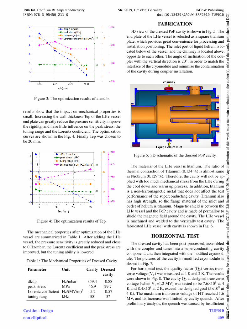
Figure 3: The optimization results of a and b.
results show that the impact on mechanical properties is
small. Increasing the wall thickness Tep of the LHe vessel
end plate can greatly reduce the pressure sensitivity, improve
the rigidity, and have little influence on the peak stress, the
tuning range and the Lorentz coefficient. The optimization
curves are shown in the Fig. 4. Finally Tep was chosen to
be 20 mm.
Figure 4: The optimization results of Tep.
The mechanical properties after optimization of the LHe
vessel are summarized in Table 1. After adding the LHe
vessel, the pressure sensitivity is greatly reduced and close
to 0 Hz/mbar, the Lorentz coefficient and the peak stress are
improved, but the tuning ability is lowered.
Table 1: The Mechanical Properties of Dressed Cavity
Parameter Unit Cavity Dressed
cavity
df/dp Hz/mbar 359.4 -0.88
peak stress MPa 46.9 29.7
Lorentz coefficient Hz/(MV/m)2 -5.2 -0.57
tuning rang kHz 100 37
FABRICATION
3D view of the dressed PoP cavity is shown in Fig. 5. The
end plate of the LHe vessel is selected as a square titanium
plate, which provides great convenience for processing and
installation positioning. The inlet port of liquid helium is lo-
cated below of the vessel, and the chimney is located above,
opposite to each other. The angle of inclination of the cou-
pler with the vertical direction is 20◦, in order to match the
interface of the cryomodule and minimize the contamination
of the cavity during coupler installation.
Figure 5: 3D schematic of the dressed PoP cavity.
The material of the LHe vessl is titanium. The ratio of
thermal contraction of Titanium (0.134 %) is almost same
as Niobium (0.129 %). Therefore, the cavity will not be ap-
plied with too much mechanical stress from the LHe during
the cool down and warm up process. In addition, titanium
is a non-ferromagnetic metal that does not affect the test
performance of the superconducting cavity. Titanium also
has high strength, so the flange material of the inlet and
outlet of helium is titanium. Magnetic shield is between the
LHe vessel and the PoP cavity and is made of permalloy to
shield the magnetic field around the cavity. The LHe vessel
is machined and welded to the vertically test cavity. The
fabricated LHe vessel with cavity is shown in Fig. 6.
HORIZONTAL TEST
The dressed cavity has been post-processed, assembled
with the coupler and tuner into a superconducting cavity
component, and then integrated with the modified cryomod-
ule. The pictures of the cavity in modified cryomodule is
shown in Fig. 7.
For horizontal test, the quality factor (Q0) versus trans-
verse voltage (Vc) was measured at 4 K and 2 K. The results
were shown in Fig. 8. The cavity Q0 at designed transverse
voltage (when Vc=1.2 MV) was tested to be 7.6×10⁸ at 4
K and 8.4×10⁸ at 2 K, exceed the designed goal (5×10⁸ at
4 K). The maximum transverse voltage of HT reached 1.6
MV, and its increase was limited by cavity quench. After
preliminary analysis, the quench was caused by insufficient
19th Int. Conf. on RF Superconductivity SRF2019, Dresden, Germany JACoW PublishingISBN: 978-3-95450-211-0 doi:10.18429/JACoW-SRF2019-TUP010
Cavities - Designnon-elliptical
TUP010409
Cont
entf
rom
this
wor
km
aybe
used
unde
rthe
term
soft
heCC
BY3.
0lic
ence
(©20
19).
Any
distr
ibut
ion
ofth
isw
ork
mus
tmai
ntai
nat
tribu
tion
toth
eau
thor
(s),
title
ofth
ew
ork,
publ
isher
,and
DO
I.
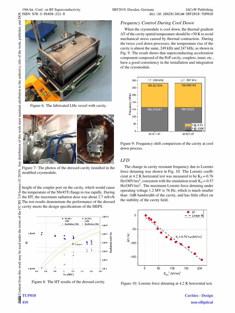
Figure 6: The fabricated LHe vessel with cavity.
Figure 7: The photos of the dressed cavity installed in the
modified cryomodule.
height of the coupler port on the cavity, which would cause
the temperature of the Nb/45Ti flange to rise rapidly. During
the HT, the maximum radiation dose was about 2.7 mSv/h.
The test results demonstrate the performance of the dressed
cavity meets the design specifications of the HEPS.
Figure 8: The HT results of the dressed cavity.
Frequency Control During Cool Down
When the cryomodule is cool down, the thermal gradient
∆T of the cavity spatial temperature should be <50 K to avoid
mechanical stress caused by thermal contraction. During
the twice cool down processes, the temperature rise of the
cavity is almost the same, 249 kHz and 247 kHz, as shown in
Fig. 9. The result shows that superconducting acceleration
component composed of the PoP cavity, couplers, tuner, etc.,
have a good consistency in the installation and integration
of the cryomodule.
Figure 9: Frequency shift comparison of the cavity at cool
down process.
LFD
The change in cavity resonant frequency due to Lorentz
force detuning was shown in Fig. 10. The Lorentz coeffi-
cient at 4.2 K horizontal test was measured to be KL=-0.76
Hz/(MV/m)2, consistent with the simulation result KL=-0.57
Hz/(MV/m)2. The maximum Lorentz force detuning under
operating voltage 1.2 MV is 76 Hz, which is much smaller
than -3dB bandwidth of the cavity, and has little effect on
the stability of the cavity field.
Figure 10: Lorentz force detuning at 4.2 K horizontal test.
19th Int. Conf. on RF Superconductivity SRF2019, Dresden, Germany JACoW PublishingISBN: 978-3-95450-211-0 doi:10.18429/JACoW-SRF2019-TUP010
TUP010410
Cont
entf
rom
this
wor
km
aybe
used
unde
rthe
term
soft
heCC
BY3.
0lic
ence
(©20
19).
Any
distr
ibut
ion
ofth
isw
ork
mus
tmai
ntai
nat
tribu
tion
toth
eau
thor
(s),
title
ofth
ew
ork,
publ
isher
,and
DO
I.
Cavities - Designnon-elliptical
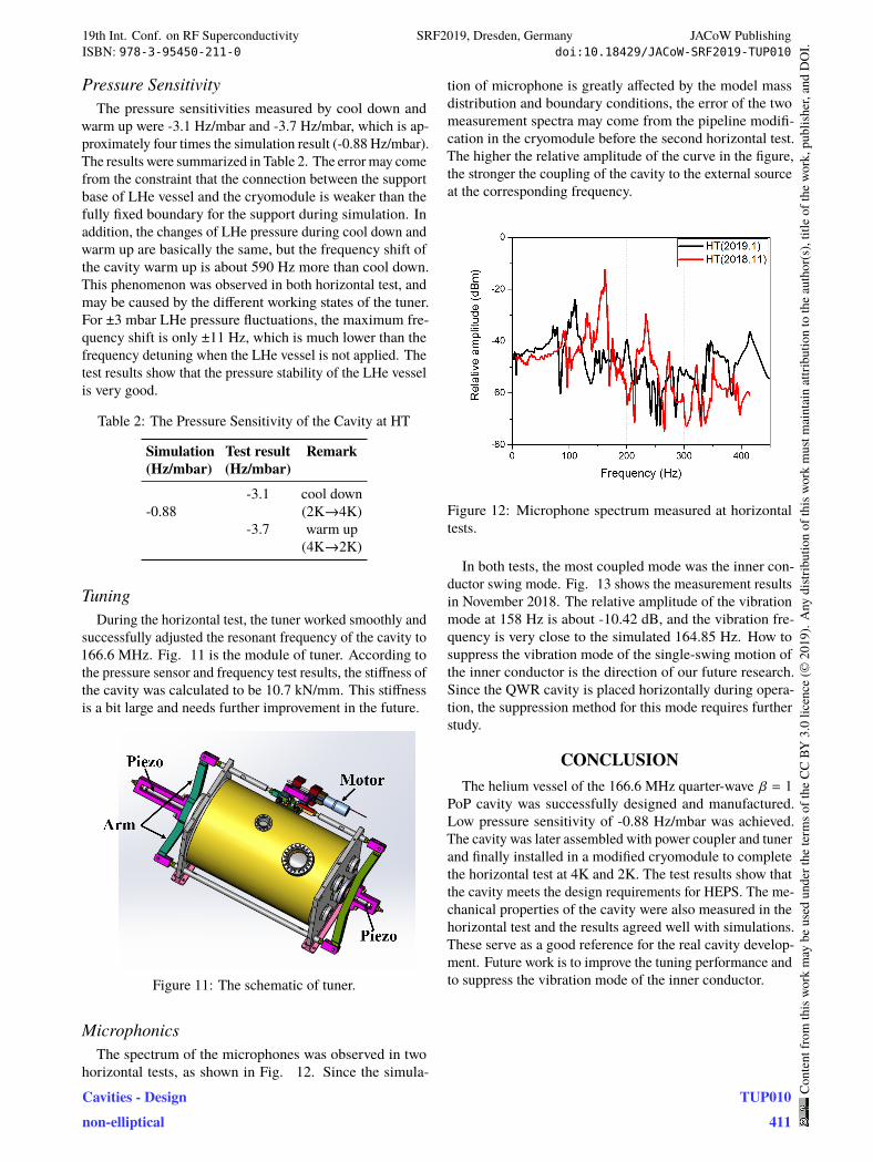
Pressure Sensitivity
The pressure sensitivities measured by cool down and
warm up were -3.1 Hz/mbar and -3.7 Hz/mbar, which is ap-
proximately four times the simulation result (-0.88 Hz/mbar).
The results were summarized in Table 2. The error may come
from the constraint that the connection between the support
base of LHe vessel and the cryomodule is weaker than the
fully fixed boundary for the support during simulation. In
addition, the changes of LHe pressure during cool down and
warm up are basically the same, but the frequency shift of
the cavity warm up is about 590 Hz more than cool down.
This phenomenon was observed in both horizontal test, and
may be caused by the different working states of the tuner.
For ±3 mbar LHe pressure fluctuations, the maximum fre-
quency shift is only ±11 Hz, which is much lower than the
frequency detuning when the LHe vessel is not applied. The
test results show that the pressure stability of the LHe vessel
is very good.
Table 2: The Pressure Sensitivity of the Cavity at HT
Simulation Test result Remark
(Hz/mbar) (Hz/mbar)
-3.1 cool down
-0.88 (2K→4K)
-3.7 warm up
(4K→2K)
Tuning
During the horizontal test, the tuner worked smoothly and
successfully adjusted the resonant frequency of the cavity to
166.6 MHz. Fig. 11 is the module of tuner. According to
the pressure sensor and frequency test results, the stiffness of
the cavity was calculated to be 10.7 kN/mm. This stiffness
is a bit large and needs further improvement in the future.
Figure 11: The schematic of tuner.
Microphonics
The spectrum of the microphones was observed in two
horizontal tests, as shown in Fig. 12. Since the simula-
tion of microphone is greatly affected by the model mass
distribution and boundary conditions, the error of the two
measurement spectra may come from the pipeline modifi-
cation in the cryomodule before the second horizontal test.
The higher the relative amplitude of the curve in the figure,
the stronger the coupling of the cavity to the external source
at the corresponding frequency.
Figure 12: Microphone spectrum measured at horizontal
tests.
In both tests, the most coupled mode was the inner con-
ductor swing mode. Fig. 13 shows the measurement results
in November 2018. The relative amplitude of the vibration
mode at 158 Hz is about -10.42 dB, and the vibration fre-
quency is very close to the simulated 164.85 Hz. How to
suppress the vibration mode of the single-swing motion of
the inner conductor is the direction of our future research.
Since the QWR cavity is placed horizontally during opera-
tion, the suppression method for this mode requires further
study.
CONCLUSION
The helium vessel of the 166.6 MHz quarter-wave β = 1
PoP cavity was successfully designed and manufactured.
Low pressure sensitivity of -0.88 Hz/mbar was achieved.
The cavity was later assembled with power coupler and tuner
and finally installed in a modified cryomodule to complete
the horizontal test at 4K and 2K. The test results show that
the cavity meets the design requirements for HEPS. The me-
chanical properties of the cavity were also measured in the
horizontal test and the results agreed well with simulations.
These serve as a good reference for the real cavity develop-
ment. Future work is to improve the tuning performance and
to suppress the vibration mode of the inner conductor.
19th Int. Conf. on RF Superconductivity SRF2019, Dresden, Germany JACoW PublishingISBN: 978-3-95450-211-0 doi:10.18429/JACoW-SRF2019-TUP010
Cavities - Designnon-elliptical
TUP010411
Cont
entf
rom
this
wor
km
aybe
used
unde
rthe
term
soft
heCC
BY3.
0lic
ence
(©20
19).
Any
distr
ibut
ion
ofth
isw
ork
mus
tmai
ntai
nat
tribu
tion
toth
eau
thor
(s),
title
ofth
ew
ork,
publ
isher
,and
DO
I.
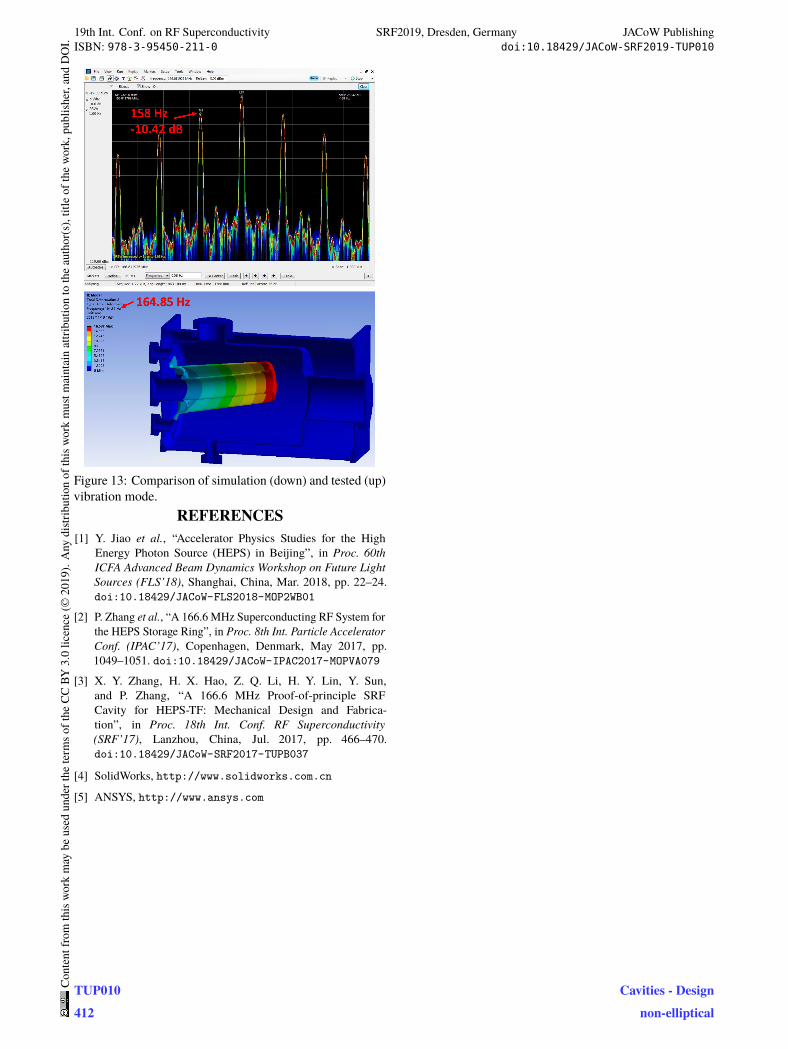
Figure 13: Comparison of simulation (down) and tested (up)
vibration mode.
Sources (FLS’18), Shanghai, China, Mar. 2018, pp. 22–24.
doi:10.18429/JACoW-FLS2018-MOP2WB01
[2] P. Zhang et al., “A 166.6 MHz Superconducting RF System for
the HEPS Storage Ring”, in Proc. 8th Int. Particle Accelerator
Conf. (IPAC’17), Copenhagen, Denmark, May 2017, pp.
1049–1051. doi:10.18429/JACoW-IPAC2017-MOPVA079
[3] X. Y. Zhang, H. X. Hao, Z. Q. Li, H. Y. Lin, Y. Sun,
and P. Zhang, “A 166.6 MHz Proof-of-principle SRF
Cavity for HEPS-TF: Mechanical Design and Fabrica-
tion”, in Proc. 18th Int. Conf. RF Superconductivity
(SRF’17), Lanzhou, China, Jul. 2017, pp. 466–470.
doi:10.18429/JACoW-SRF2017-TUPB037
[4] SolidWorks, http://www.solidworks.com.cn
[5] ANSYS, http://www.ansys.com
REFERENCES
[1] Y. Jiao et al., “Accelerator Physics Studies for the High
Energy Photon Source (HEPS) in Beijing”, in Proc. 60th
ICFA Advanced Beam Dynamics Workshop on Future Light
19th Int. Conf. on RF Superconductivity SRF2019, Dresden, Germany JACoW PublishingISBN: 978-3-95450-211-0 doi:10.18429/JACoW-SRF2019-TUP010
TUP010412
Cont
entf
rom
this
wor
km
aybe
used
unde
rthe
term
soft
heCC
BY3.
0lic
ence
(©20
19).
Any
distr
ibut
ion
ofth
isw
ork
mus
tmai
ntai
nat
tribu
tion
toth
eau
thor
(s),
title
ofth
ew
ork,
publ
isher
,and
DO
I.
Cavities - Designnon-elliptical


![AMINO ACIDS [QUALITATIVE TESTS] BCH 302 [PRACTICAL]](https://static.fdocument.org/doc/165x107/56649db35503460f94aa38d5/amino-acids-qualitative-tests-bch-302-practical.jpg)