ME36500 Homework #10 Due: 11/20/2014 - Purdue...
2
ME36500 Homework #10 Due: 11/20/2014 1/2 Problem #1 (40%) Strain gages and the two active arm bridge configuration shown below are to be used to convert change in resistance due to strain into changes in voltage. Z1 Z2 Z1 =R0 + ΔR+ ΔRT Z2 =R0 Vsupply Z3 =R0 – ΔR+ ΔRT Z4 =R0 Z4 Z3 Vout R0 is the rest resistance of the strain gage and the resistance of the resistors, ΔR is the change in resistance due to strain, and ΔRT is the change in resistance due to changes in temperature. (A) Derive an expression for the output of the bridge (Vout) in terms of the input (change in resistance). (B) Swap the impedances for Z3 and Z4, making Z4 the second active arm. Derive the new expression for the output of the bridge in terms of input. (C) State which configuration is preferable and why. (D) If R0 is 120 Ω, and Imax is 30 mA, what is the maximum allowable supply voltage? (E) What is the output voltage if the strain seen by the gages used in the second configuration is 500 μin/in, the gage factor is 2.07, and Vsupply is 5 V? Problem #2 (30%) The ability to measure a stem cell’s mass is important since it reveals information about how close it is to mitosis (cell division). A device that detects the cell as early in its cell cycle (when it is small) as possible would be of great impact. As a mechanical engineer, you wonder whether you can design a cellmass sensor with a micromachined cantilever beam (equipped with a strain gage) to detect the mass of a cell sitting at its tip: You know that the strain ε on a cantilever beam’s top surface is related to a vertical force F applied at its tip by the following equation: ε = t 2 F (L − x ) EI where L is the length of the cantilever beam, E is the Young’s modulus, I is the moment of inertia and t is the thickness of the cantilever. x is the distance from the base of the cantilever. You also remember that the moment of inertia of a cantilever beam with uniform rectangular crosssectional area is I = wt 3 12 with w denoting the width of the crosssectional area. cell
Transcript of ME36500 Homework #10 Due: 11/20/2014 - Purdue...
ME36500 Homework #10 Due: 11/20/2014
1/2
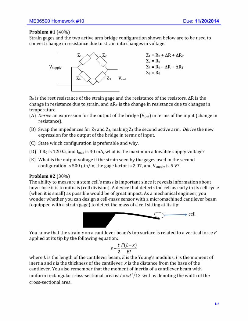
Problem #1 (40%) Strain gages and the two active arm bridge configuration shown below are to be used to convert change in resistance due to strain into changes in voltage. Z1 Z2 Z1 = R0 + ΔR + ΔRT Z2 = R0 Vsupply Z3 = R0 – ΔR + ΔRT Z4 = R0 Z4 Z3 Vout
R0 is the rest resistance of the strain gage and the resistance of the resistors, ΔR is the change in resistance due to strain, and ΔRT is the change in resistance due to changes in temperature. (A) Derive an expression for the output of the bridge (Vout) in terms of the input (change in
resistance).
(B) Swap the impedances for Z3 and Z4, making Z4 the second active arm. Derive the new expression for the output of the bridge in terms of input.
(C) State which configuration is preferable and why.
(D) If R0 is 120 Ω, and Imax is 30 mA, what is the maximum allowable supply voltage? (E) What is the output voltage if the strain seen by the gages used in the second
configuration is 500 µin/in, the gage factor is 2.07, and Vsupply is 5 V?
Problem #2 (30%) The ability to measure a stem cell’s mass is important since it reveals information about how close it is to mitosis (cell division). A device that detects the cell as early in its cell cycle (when it is small) as possible would be of great impact. As a mechanical engineer, you wonder whether you can design a cell-‐mass sensor with a micromachined cantilever beam (equipped with a strain gage) to detect the mass of a cell sitting at its tip:
You know that the strain ε on a cantilever beam’s top surface is related to a vertical force F applied at its tip by the following equation:
!!ε =
t2F(L− x)EI
where L is the length of the cantilever beam, E is the Young’s modulus, I is the moment of inertia and t is the thickness of the cantilever. x is the distance from the base of the cantilever. You also remember that the moment of inertia of a cantilever beam with uniform rectangular cross-‐sectional area is !!I =wt
3 12 with w denoting the width of the cross-‐sectional area.
cell
ME36500 Homework #10 Due: 11/20/2014
2/2
(A) Decide where on the top surface a strain gage should be located. Close to the base? Close to the tip? Explain.
(B) Based on your decision, express the strain that your gage would experience in terms of the cell mass and the properties of the cantilever.
(C) Assuming that you use a bridge circuit (where the only active resistor is your strain gage) in conjunction with a digital measurement device whose quantization level is Q, determine the smallest mass that you can detect in terms of the quantization interval, the bridge’s supply voltage and other relevant properties of the strain gage and the cantilever.
(D) Suggest modifications to the detection system in order to improve your resolution, i.e., minimum detectable cell mass
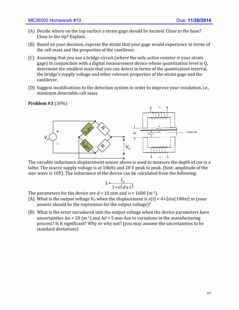
Problem #3 (30%)
The variable inductance displacement sensor above is used to measure the depth of cut in a lathe. The source supply voltage is at 10kHz and 20 V peak to peak. (hint: amplitude of the sine wave is 10V). The inductance of the device can be calculated from the following:
!!L=
L01+α d± x( )
The parameters for the device are d = 10 mm and α = 1600 (m-‐1). (A) What is the output voltage VO when the displacement is x(t) = 4+2sin(100πt) m (your
answer should be the expression for the output voltage)? (B) What is the error introduced into the output voltage when the device parameters have
uncertainties Δα = 20 (m-‐1) and Δd = 5 mm due to variations in the manufacturing process? Is it significant? Why or why not? (you may assume the uncertainties to be standard deviations)