Low and Intermediate β Cavity - CERNMAFIA, Microwave Studio, HFSS, etc. 3D software is usually very...
28
Thomas Jefferson National Accelerator Facility Operated by the Southeastern Universities Research Association for the U.S. Department of Energy Low and Intermediate β Cavity Design A Tutorial Jean Delayen Jefferson Lab 2003 SRF Workshop
Transcript of Low and Intermediate β Cavity - CERNMAFIA, Microwave Studio, HFSS, etc. 3D software is usually very...
Thomas Jefferson National Accelerator FacilityOperated by the Southeastern Universities Research Association for the U.S. Department of Energy
Low and Intermediate βCavity Design
A Tutorial
Jean DelayenJefferson Lab
2003 SRF Workshop
Operated by the Southeastern Universities Research Association for the U.S. Department of Energy
Thomas Jefferson National Accelerator Facility Page 2
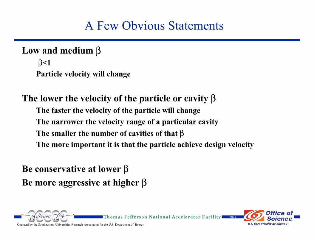
A Few Obvious Statements
Low and medium ββ<1Particle velocity will change
The lower the velocity of the particle or cavity βThe faster the velocity of the particle will changeThe narrower the velocity range of a particular cavityThe smaller the number of cavities of that βThe more important it is that the particle achieve design velocity
Be conservative at lower βBe more aggressive at higher β
Operated by the Southeastern Universities Research Association for the U.S. Department of Energy
Thomas Jefferson National Accelerator Facility Page 3
Two main types of structure geometriesTEM class (QW, HW, Spoke)TM class (elliptical)
Design issues of medium β elliptical cavities are similar to those of β=1Most of the talk will be on TEM-class cavitiesFor TM-class cavities see:
Design criteria for elliptical cavitiesPagani, Barni, Bosotti, Pierini, Ciovati, SRF 2001.
Challenges and the future of reduced beta srf cavity designSang-ho Kim, LINAC 2002.
A Few More Statements
Operated by the Southeastern Universities Research Association for the U.S. Department of Energy
Thomas Jefferson National Accelerator Facility Page 4
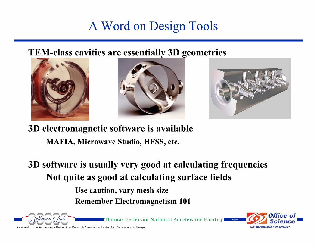
A Word on Design Tools
TEM-class cavities are essentially 3D geometries
3D electromagnetic software is availableMAFIA, Microwave Studio, HFSS, etc.
3D software is usually very good at calculating frequenciesNot quite as good at calculating surface fields
Use caution, vary mesh sizeRemember Electromagnetism 101
Operated by the Southeastern Universities Research Association for the U.S. Department of Energy
Thomas Jefferson National Accelerator Facility Page 5
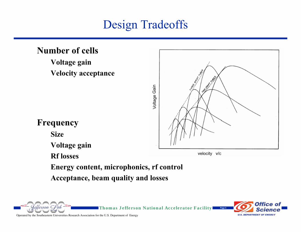
Design Tradeoffs
Number of cellsVoltage gainVelocity acceptance
FrequencySizeVoltage gainRf lossesEnergy content, microphonics, rf controlAcceptance, beam quality and losses
Operated by the Southeastern Universities Research Association for the U.S. Department of Energy
Thomas Jefferson National Accelerator Facility Page 6
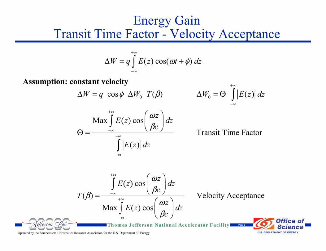
Energy Gain Transit Time Factor - Velocity Acceptance
Assumption: constant velocity
( ) cos( )W q E z t dzω φ∆+•
-•
= +Ú
0 0cos ( ) ( )
Max ( ) cosTransit Time Factor
( )
( ) cos( ) Velocity Acceptance
Max ( ) cos
W q W T W E z dz
zE z dzc
E z dz
zE z dzc
TzE z dzc
φ β
ωβ
ωβ
βωβ
∆ ∆ ∆ Θ
Θ
+•
-•+•
-•+•
-•
+•
-•+•
-•
= =
Ê ˆÁ ˜Ë ¯
=
Ê ˆÁ ˜Ë ¯
=Ê ˆÁ ˜Ë ¯
Ú
Ú
Ú
Ú
Ú
Operated by the Southeastern Universities Research Association for the U.S. Department of Energy
Thomas Jefferson National Accelerator Facility Page 7
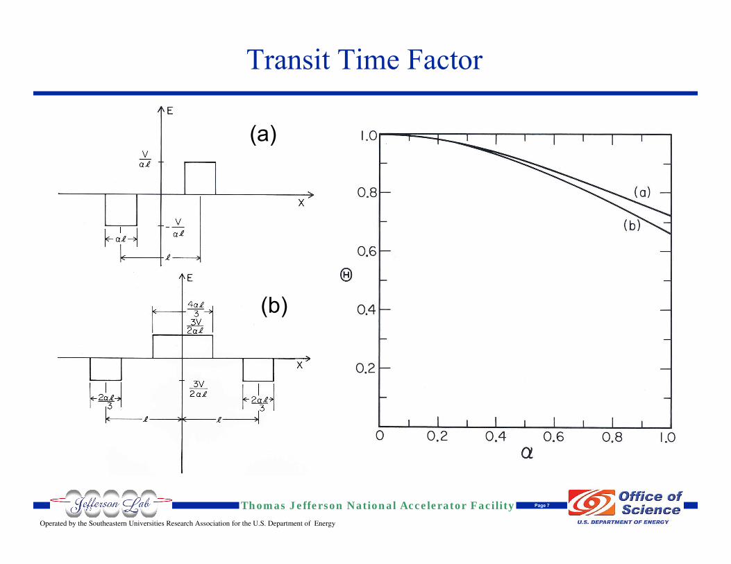
Transit Time Factor
(a)
(b)
Operated by the Southeastern Universities Research Association for the U.S. Department of Energy
Thomas Jefferson National Accelerator Facility Page 8
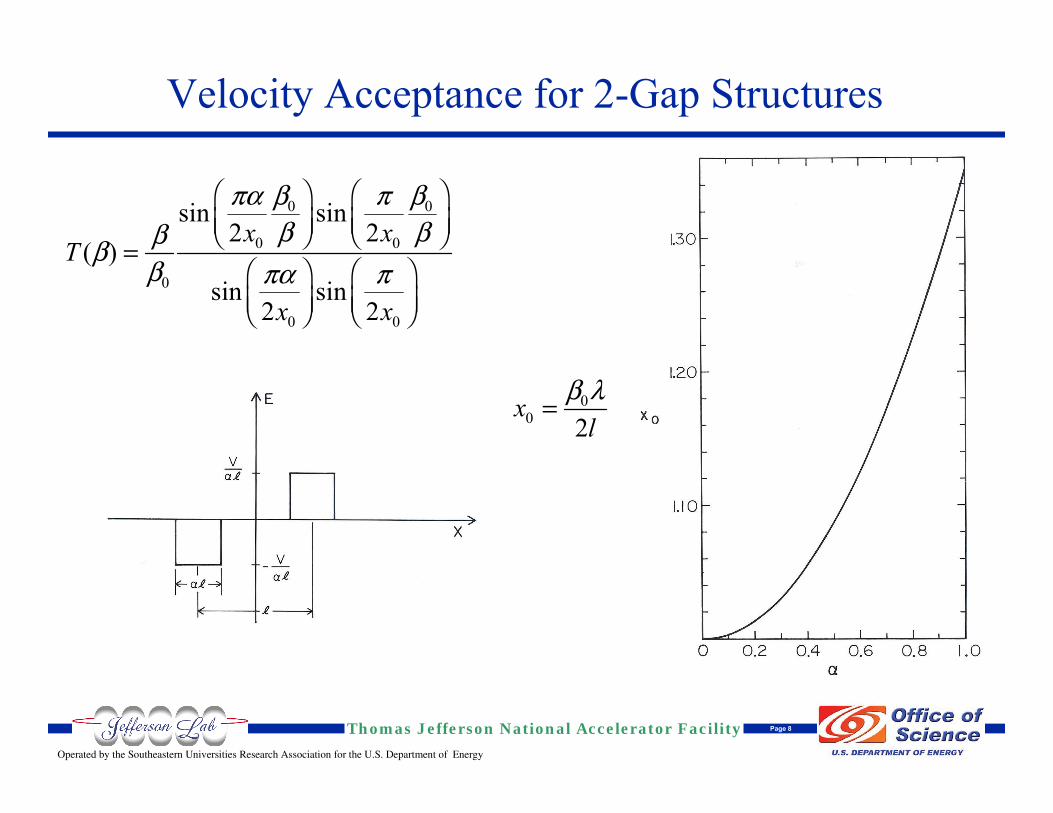
Velocity Acceptance for 2-Gap Structures
0 0
0 0
0
0 0
sin sin2 2
( )sin sin
2 2
x xT
x x
β βπα πβ βββ
β πα π
Ê ˆ Ê ˆÁ ˜ Á ˜Ë ¯ Ë ¯
=Ê ˆ Ê ˆÁ ˜ Á ˜Ë ¯ Ë ¯
00 2x
lβ λ=
Operated by the Southeastern Universities Research Association for the U.S. Department of Energy
Thomas Jefferson National Accelerator Facility Page 9
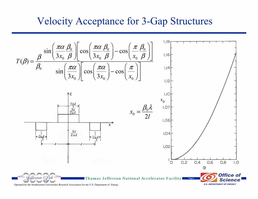
Velocity Acceptance for 3-Gap Structures
0 0 0
0 0 0
0
0 0 0
sin cos cos3 3
( )sin cos cos
3 3
x x xT
x x x
β β βπα πα πβ β βββ
β πα πα π
È ˘Ê ˆ Ê ˆ Ê ˆ-Í ˙Á ˜ Á ˜ Á ˜Ë ¯ Ë ¯ Ë ¯Î ˚=
È ˘Ê ˆ Ê ˆ Ê ˆ-Í ˙Á ˜ Á ˜ Á ˜Ë ¯ Ë ¯ Ë ¯Î ˚
00 2x
lβ λ=
Operated by the Southeastern Universities Research Association for the U.S. Department of Energy
Thomas Jefferson National Accelerator Facility Page 10
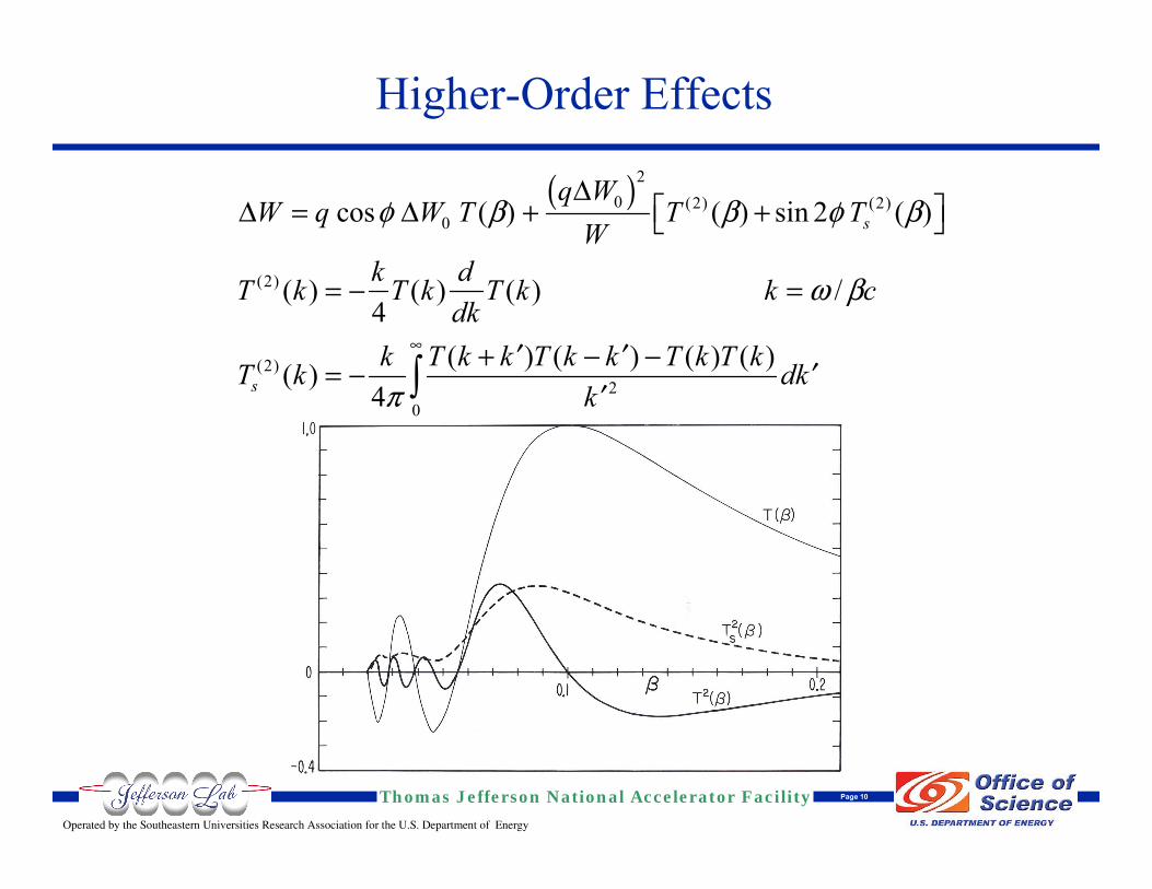
Higher-Order Effects
( )20 (2) (2)0
(2)
(2)2
0
cos ( ) ( ) sin 2 ( )
( ) ( ) ( ) /4
( ) ( ) ( ) ( )( )4
s
s
q WW q W T T T
Wk dT k T k T k k c
dkk T k k T k k T k T kT k dk
k
φ β β φ β
ω β
π
∆∆ ∆
•
È ˘= + +Î ˚
= - =
+ - -¢ ¢= - ¢¢Ú
Operated by the Southeastern Universities Research Association for the U.S. Department of Energy
Thomas Jefferson National Accelerator Facility Page 11
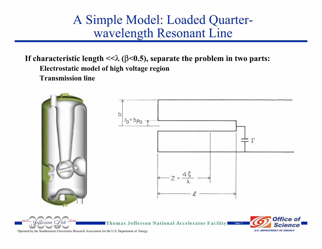
If characteristic length <<λ (β<0.5), separate the problem in two parts:Electrostatic model of high voltage regionTransmission line
A Simple Model: Loaded Quarter-wavelength Resonant Line
Operated by the Southeastern Universities Research Association for the U.S. Department of Energy
Thomas Jefferson National Accelerator Facility Page 12
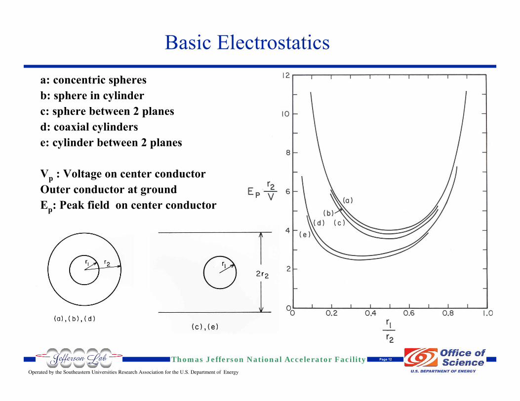
Basic Electrostaticsa: concentric spheresb: sphere in cylinderc: sphere between 2 planesd: coaxial cylinderse: cylinder between 2 planes
Vp : Voltage on center conductorOuter conductor at groundEp: Peak field on center conductor
Operated by the Southeastern Universities Research Association for the U.S. Department of Energy
Thomas Jefferson National Accelerator Facility Page 13
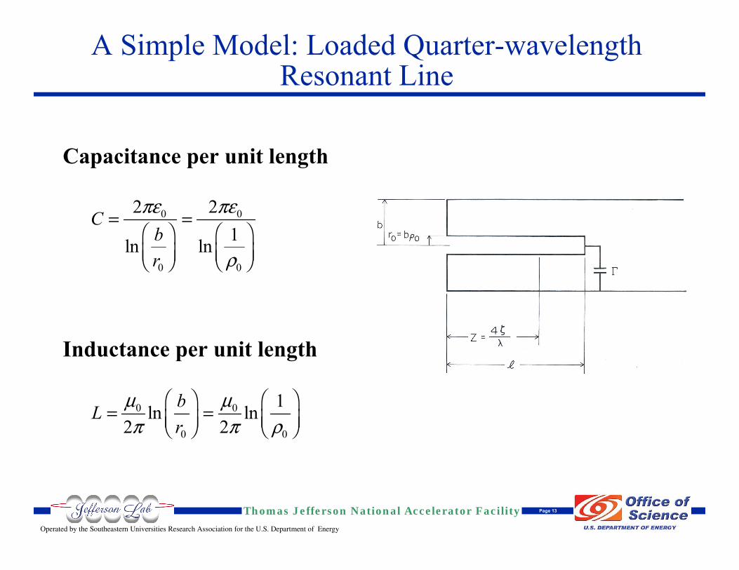
A Simple Model: Loaded Quarter-wavelength Resonant Line
Capacitance per unit length
Inductance per unit length
0 0
0 0
2 21ln ln
Cbr
πε πε
ρ
= =Ê ˆ Ê ˆÁ ˜ Á ˜Ë ¯ Ë ¯
0 0
0 0
1ln ln2 2
bLr
µ µπ π ρ
Ê ˆ Ê ˆ= =Á ˜ Á ˜Ë ¯ Ë ¯
Operated by the Southeastern Universities Research Association for the U.S. Department of Energy
Thomas Jefferson National Accelerator Facility Page 14
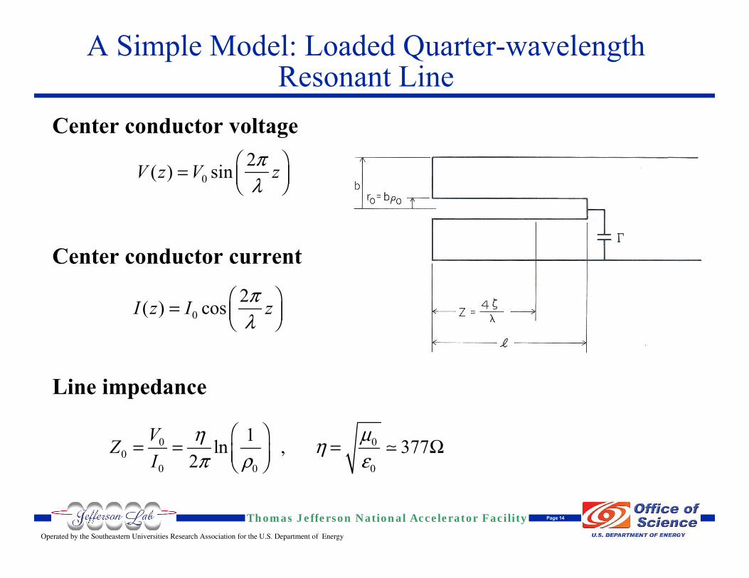
Center conductor voltage
Center conductor current
Line impedance
A Simple Model: Loaded Quarter-wavelength Resonant Line
02( ) sinV z V zπλ
Ê ˆ= Á ˜Ë ¯
02( ) cosI z I zπλ
Ê ˆ= Á ˜Ë ¯
0 00
0 0 0
1ln , 3772
VZI
µη ηπ ρ ε
ΩÊ ˆ
= = =Á ˜Ë ¯
Operated by the Southeastern Universities Research Association for the U.S. Department of Energy
Thomas Jefferson National Accelerator Facility Page 15
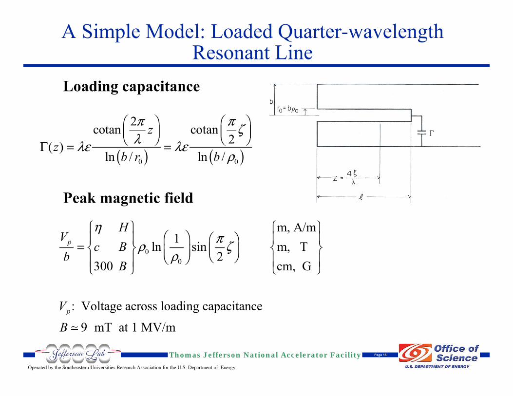
Loading capacitance
Peak magnetic field
A Simple Model: Loaded Quarter-wavelength Resonant Line
( ) ( )0 0
2cotan cotan2( )
ln / ln /
zz
b r b
π π ζλλε λε
ρΓ
Ê ˆ Ê ˆÁ ˜ Á ˜Ë ¯ Ë ¯
= =
00
m, A/m1ln sin m, T
2300 cm, G
: Voltage across loading capacitance
9 mT at 1 MV/m
p
p
HV
c Bb
B
VB
ηπρ ζ
ρ
Ï ¸ Ï ¸Ê ˆÔ Ô Ô ÔÊ ˆ= Ì ˝ Ì ˝Á ˜Á ˜ Ë ¯Ë ¯Ô Ô Ô ÔÓ ˛ Ó ˛
Operated by the Southeastern Universities Research Association for the U.S. Department of Energy
Thomas Jefferson National Accelerator Facility Page 16
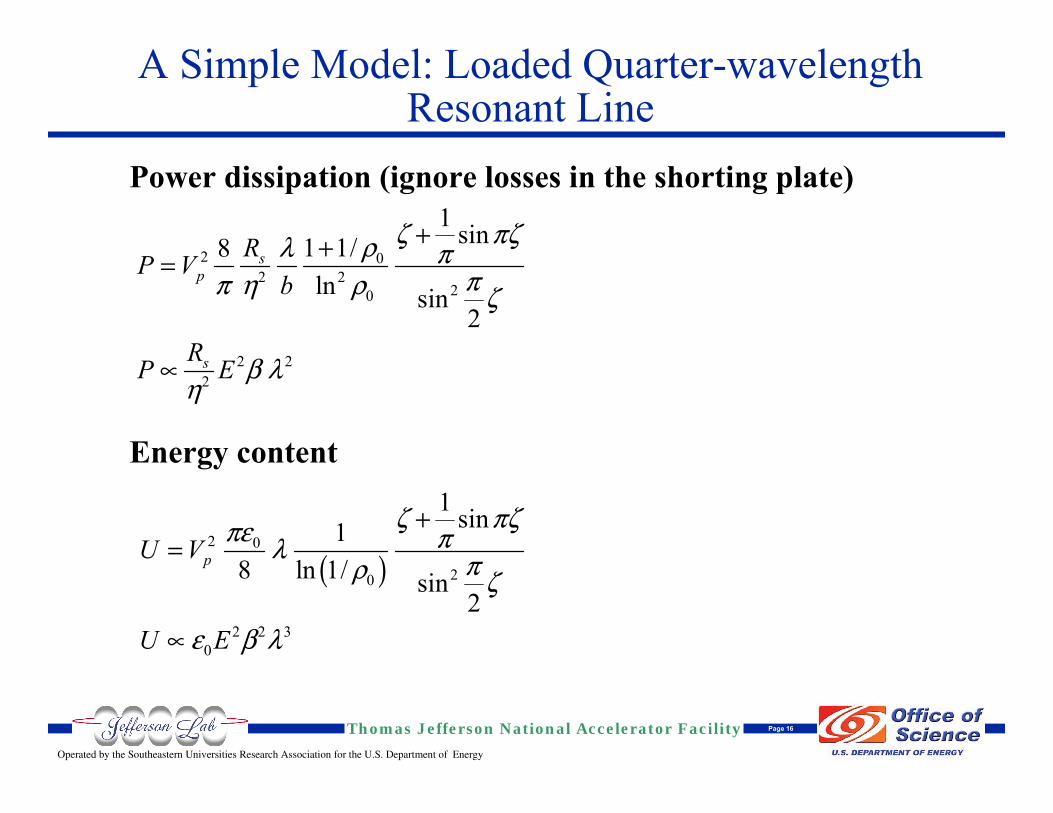
Power dissipation (ignore losses in the shorting plate)
Energy content
A Simple Model: Loaded Quarter-wavelength Resonant Line
2 02 2
20
2 22
1 sin1 1/8ln sin
2
sp
s
RP Vb
RP E
ζ πζρλ πππ η ρ ζ
β λη
++=
µ
( )2 0
20
2 2 30
1 sin18 ln 1/ sin
2
pU V
U E
ζ πζπε πλ πρ ζ
ε β λ
+=
µ
Operated by the Southeastern Universities Research Association for the U.S. Department of Energy
Thomas Jefferson National Accelerator Facility Page 17
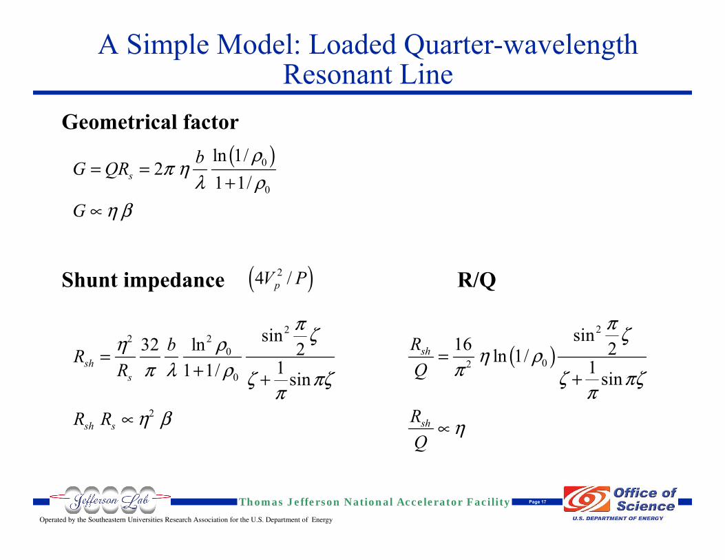
Geometrical factor
Shunt impedance R/Q
A Simple Model: Loaded Quarter-wavelength Resonant Line
( )00
ln 1/2
1 1/sbG QR
G
ρπ η
λ ρη β
= =+
µ
222
0
0
2
sinln32 211 1/ sin
shs
sh s
bRR
R R
π ζρηπ λ ρ ζ πζ
πη β
=+ +
µ
( )24 /pV P
( )2
02
sin16 2ln 1/ 1 sin
sh
sh
RQ
RQ
π ζη ρ
π ζ πζπ
η
=+
µ
Operated by the Southeastern Universities Research Association for the U.S. Department of Energy
Thomas Jefferson National Accelerator Facility Page 18
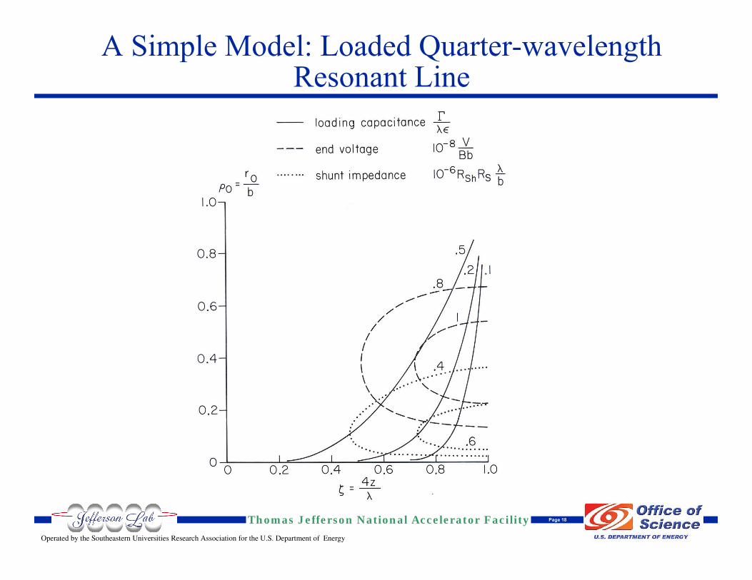
A Simple Model: Loaded Quarter-wavelength Resonant Line
Operated by the Southeastern Universities Research Association for the U.S. Department of Energy
Thomas Jefferson National Accelerator Facility Page 19
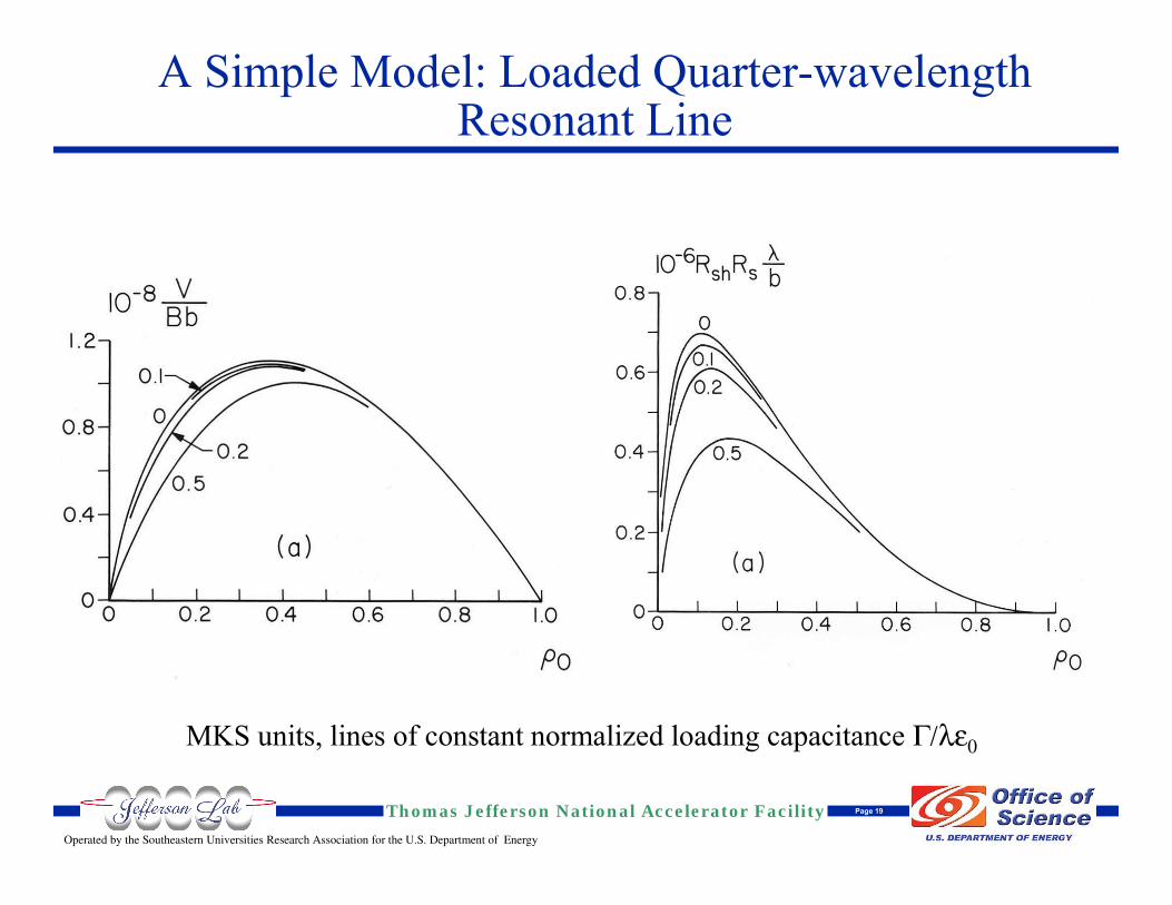
A Simple Model: Loaded Quarter-wavelength Resonant Line
MKS units, lines of constant normalized loading capacitance Γ/λε0
Operated by the Southeastern Universities Research Association for the U.S. Department of Energy
Thomas Jefferson National Accelerator Facility Page 20
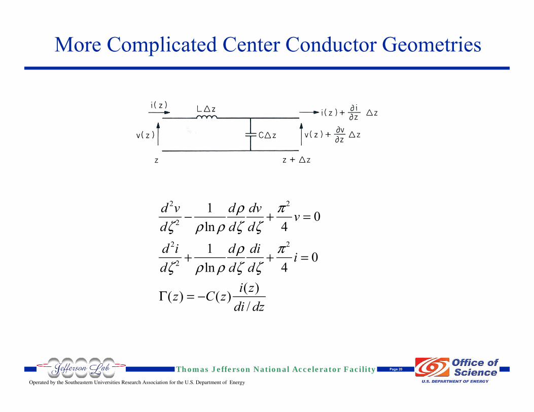
More Complicated Center Conductor Geometries
2 2
2
2 2
2
1 0ln 41 0ln 4
( )( ) ( )/
d v d dv vd d dd i d di id d d
i zz C zdi dz
ρ πζ ρ ρ ζ ζ
ρ πζ ρ ρ ζ ζ
Γ
- + =
+ + =
= -
Operated by the Southeastern Universities Research Association for the U.S. Department of Energy
Thomas Jefferson National Accelerator Facility Page 21
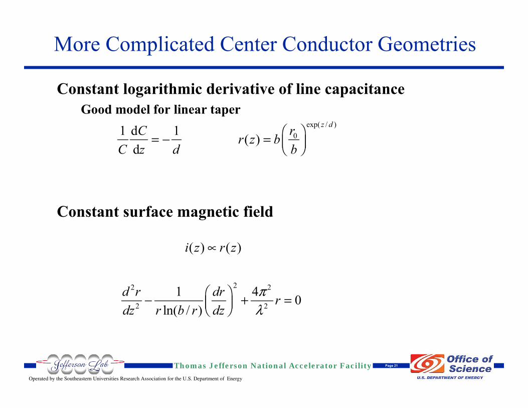
Constant logarithmic derivative of line capacitanceGood model for linear taper
Constant surface magnetic field
exp( / )01 d 1 ( )
d
z drC r z bC z d b
Ê ˆ= - = Á ˜Ë ¯
( ) ( )i z r zµ
22 2
2 2
1 4 0ln( / )
d r dr rdz r b r dz
πλ
Ê ˆ- + =Á ˜Ë ¯
More Complicated Center Conductor Geometries
Operated by the Southeastern Universities Research Association for the U.S. Department of Energy
Thomas Jefferson National Accelerator Facility Page 22
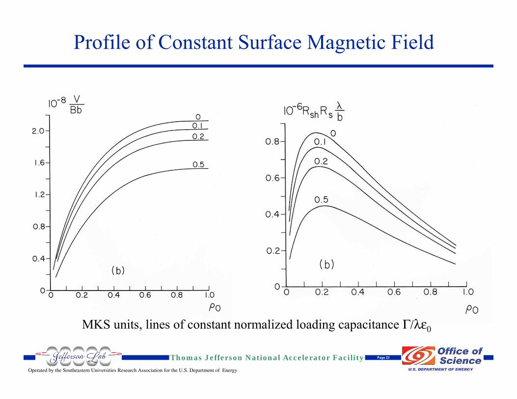
Profile of Constant Surface Magnetic Field
Operated by the Southeastern Universities Research Association for the U.S. Department of Energy
Thomas Jefferson National Accelerator Facility Page 23
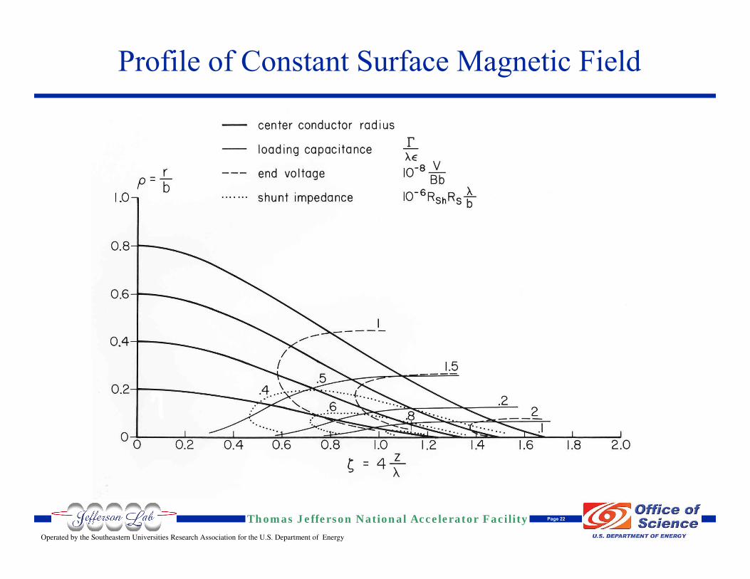
Profile of Constant Surface Magnetic Field
MKS units, lines of constant normalized loading capacitance Γ/λε0
Operated by the Southeastern Universities Research Association for the U.S. Department of Energy
Thomas Jefferson National Accelerator Facility Page 24
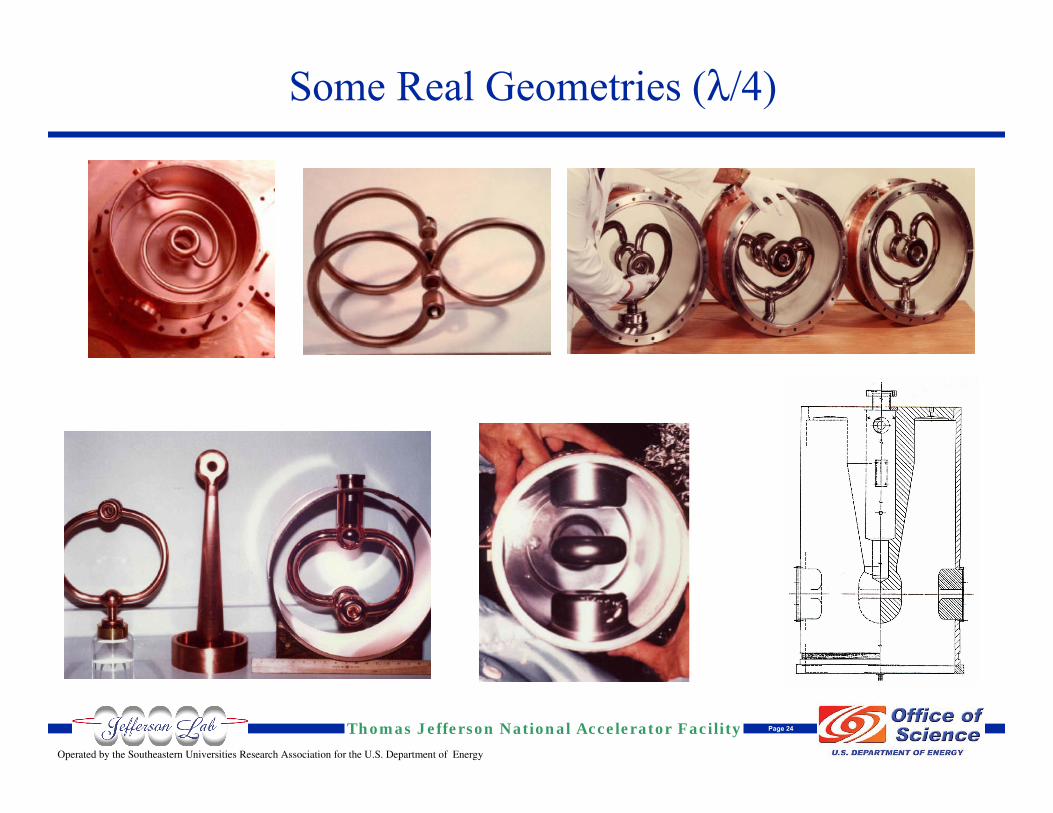
Some Real Geometries (λ/4)
Operated by the Southeastern Universities Research Association for the U.S. Department of Energy
Thomas Jefferson National Accelerator Facility Page 25
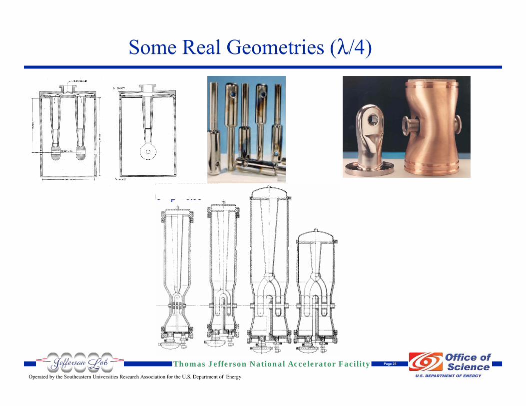
Some Real Geometries (λ/4)
Operated by the Southeastern Universities Research Association for the U.S. Department of Energy
Thomas Jefferson National Accelerator Facility Page 26
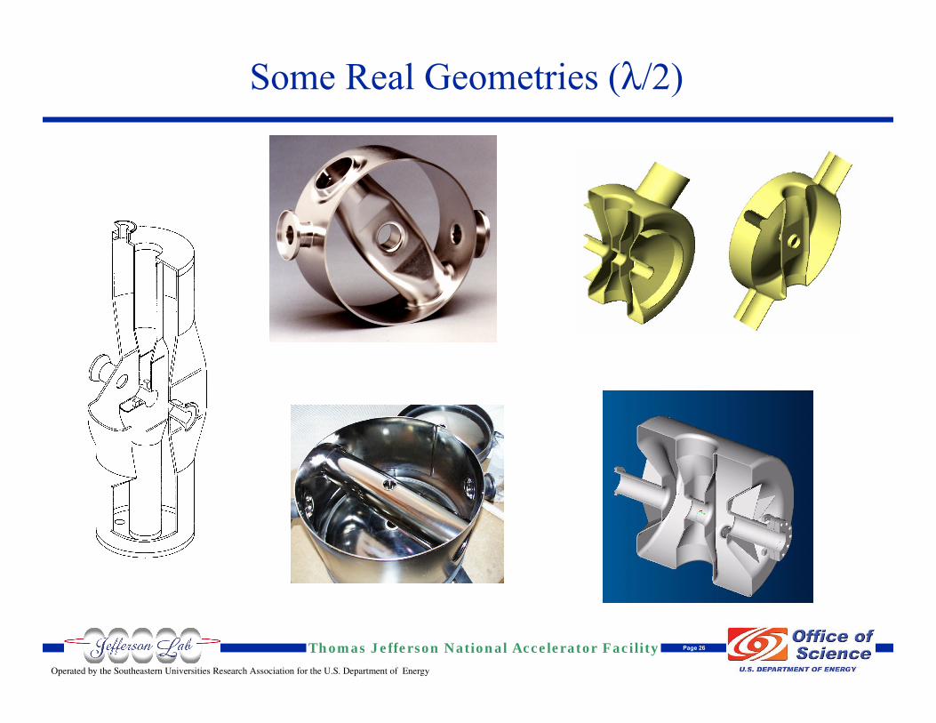
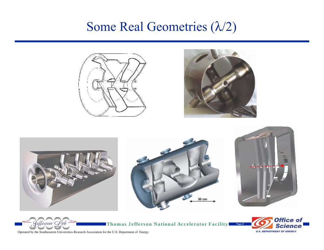
Some Real Geometries (λ/2)
Operated by the Southeastern Universities Research Association for the U.S. Department of Energy
Thomas Jefferson National Accelerator Facility Page 27
Some Real Geometries (λ/2)
Operated by the Southeastern Universities Research Association for the U.S. Department of Energy
Thomas Jefferson National Accelerator Facility Page 28
Parting Words
In the last 30+ years, the development of low and medium βsuperconducting cavities has been one of the richest and most imaginative area of srfThe field has been in perpetual evolution and progressNew geometries are constantly being developedThe final word has not been said
The parameter, tradeoff, and option space available to the designer is large
The design process is not, and probably will never be, reduced to a few simple rules or recipesThere will always be ample opportunities for imagination, originality, and common sense