Lecture 9 Chapter 26 Fall 2012 - University of Alabama at ...
14
PH 222-2C Fall 2012 CURRENT AND RESISTANCE Lecture 9 Chapter 26 (Halliday/Resnick/Walker, Fundamentals of Physics 8 th edition) 1
Transcript of Lecture 9 Chapter 26 Fall 2012 - University of Alabama at ...
PH 222-2C Fall 2012
CURRENT AND RESISTANCE
Lecture 9
Chapter 26(Halliday/Resnick/Walker, Fundamentals of Physics 8th edition)
1
Chapter 26Current and Resistance
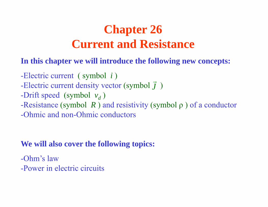
In this chapter we will introduce the following new concepts:
-Electric current ( symbol i )-Electric current density vector (symbol )-Drift speed (symbol vd )-Resistance (symbol R ) and resistivity (symbol ρ ) of a conductor -Ohmic and non-Ohmic conductors
We will also cover the following topics:
-Ohm’s law -Power in electric circuits
J
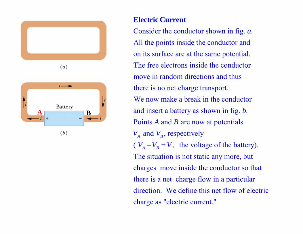
Consider the conductor shown in fig. . All the points inside the conductor and on its surface are at the same potential. The free electrons inside the conductor move in random direct
aElectric Current
ions and thus there is no net charge transport. We now make a break in the conductorand insert a battery as shown in fig. .Points and are now at potentials
and , respectively( , the
A B
A B
bA B
V VV V V voltage of the battery).
The situation is not static any more, but charges move inside the conductor so thatthere is a net charge flow in a particulardirection. We define this net flow of electric charge as "electric current."
A B
i
+ q
conductor
v
i
- q
conductor
v
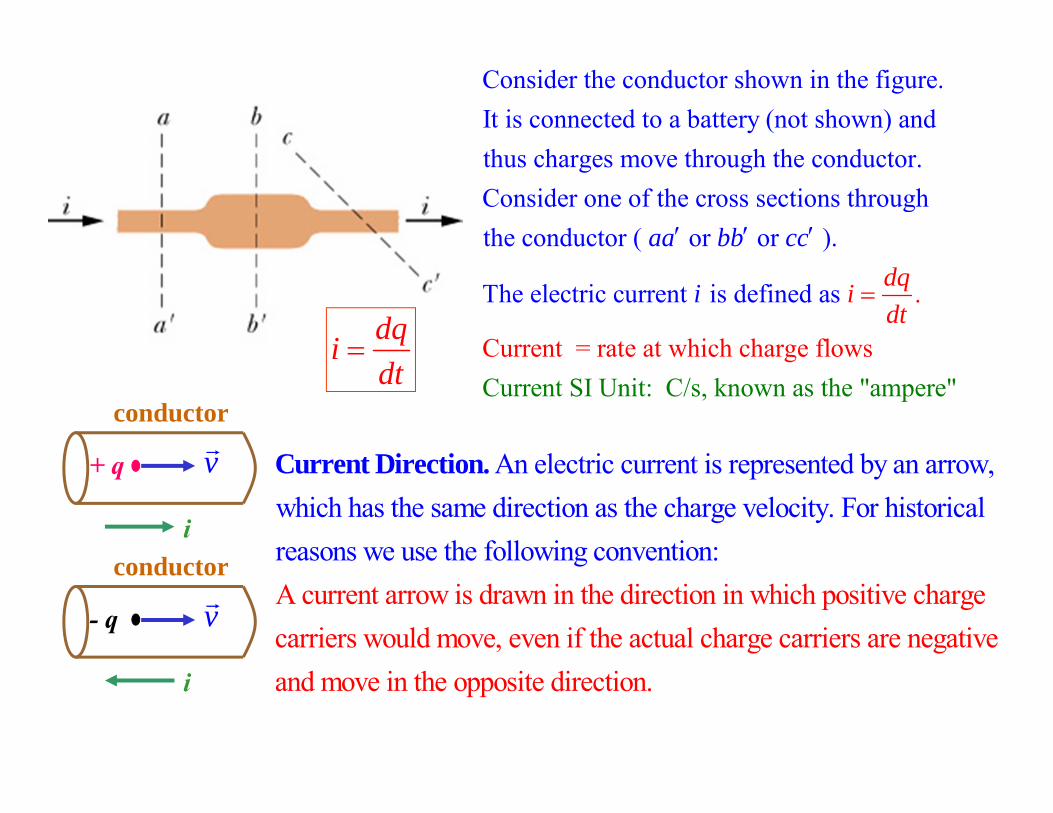
Consider the conductor shown in the figure.It is connected to a battery (not shown) andthus charges move through the conductor.Consider one of the cross sections through the conductor ( or or aa bb
.
Current = rate at which charge flo
).
The electric current is defi
Current SI Unit: C/s, kno
ned as
wn as the "ampere" ws
dcc
ii qdt
An electric current is represented by an arrow, which has the same direction as the charge velocity. For historical reasons we use the following conventiA current arrow is drawn
on:
Current Direction.
in the direction in which positive charge carriers would move, even if the actual charge carriers are negativeand move in the opposite direction.
dqidt
i
- q
conductor
v A
J
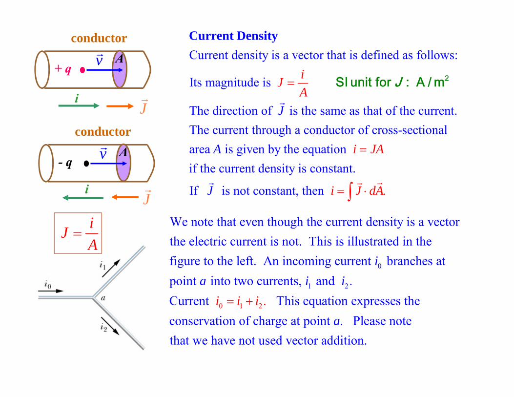
Current density is a vector that is defined as follows:
Its magnitude is
The direction of is the same as that of the current.The current through a c
o
i
J
JA
Current Density
2SI unit for : A / mJ
nductor of cross-sectionalarea is given by the equation if the current density is constant.
If is not constant, then
.
i JA
i dJ J
A
A
i
+ q
conductor
v A
J
0
1
We note that even though the current density is a vectorthe electric current is not. This is illustrated in the figure to the left. An incoming current branches atpoint into two currents, an
ia i 2
0 1 2
d . Current This equation expresses theconservation of charge at point . Please note that we have not used vector addition.
.i i ii
a
iJA
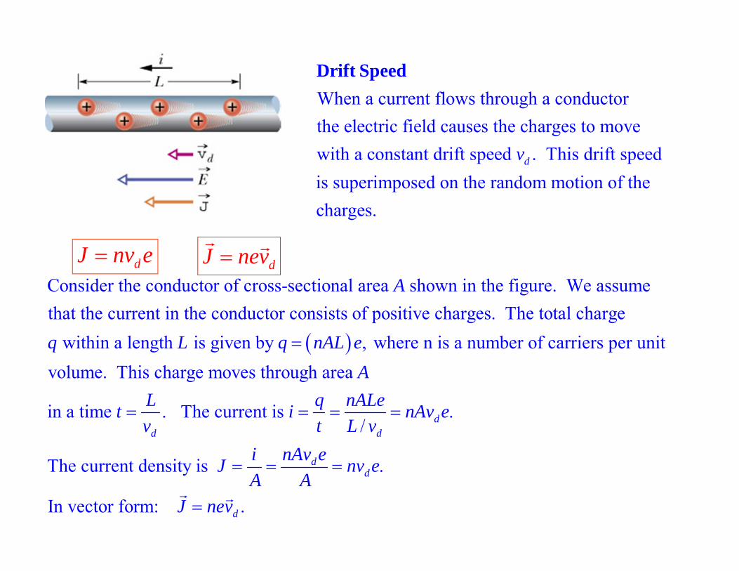
When a current flows through a conductorthe electric field causes the charges to movewith a constant drift speed . This drift speedis superimposed on the random motion of the charges.
dv
Drift Speed
Consider the conductor of cross-sectional area shown in the figure. We assumethat the current in the conductor consists of positive charges. The total charge
within a length is given by ,
A
q L q nAL e where n is a number of carriers per unit volume. This charge moves through area
in a time . The current is ./
The current density is .
In vector form:
dd d
dd
AL q nALet i nAv ev t L v
i nAv eJ nv eA A
J
.dnev
dJ nev
dJ nv e
+ -
i
V
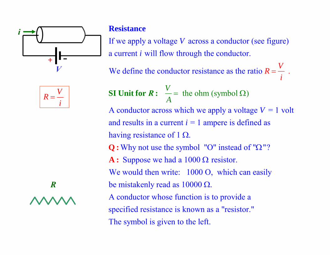
If we apply a voltage across a conductor (see figure)a current will flow through the conductor.
We define the conductor resistance as the ratio
the ohm (symbo
.VRi
V
Vi
A
SI Unit for
Resistan
:
ce
R
A conductor across which we apply a voltage = 1 voltand results in a current = 1 ampere is defined as having resistance of 1 .
Why not use the symbol "O" instead of " "? Suppose we ha
l )
Vi
Q :A :
d a 1000 resistor.
We would then write: 1000 O, which can easily be mistakenly read as 10000 .A conductor whose function is to provide a specified resistance is known as a "resistor." The symbo
l is given to the left.
VRi
R
E
+ -
i
V
E
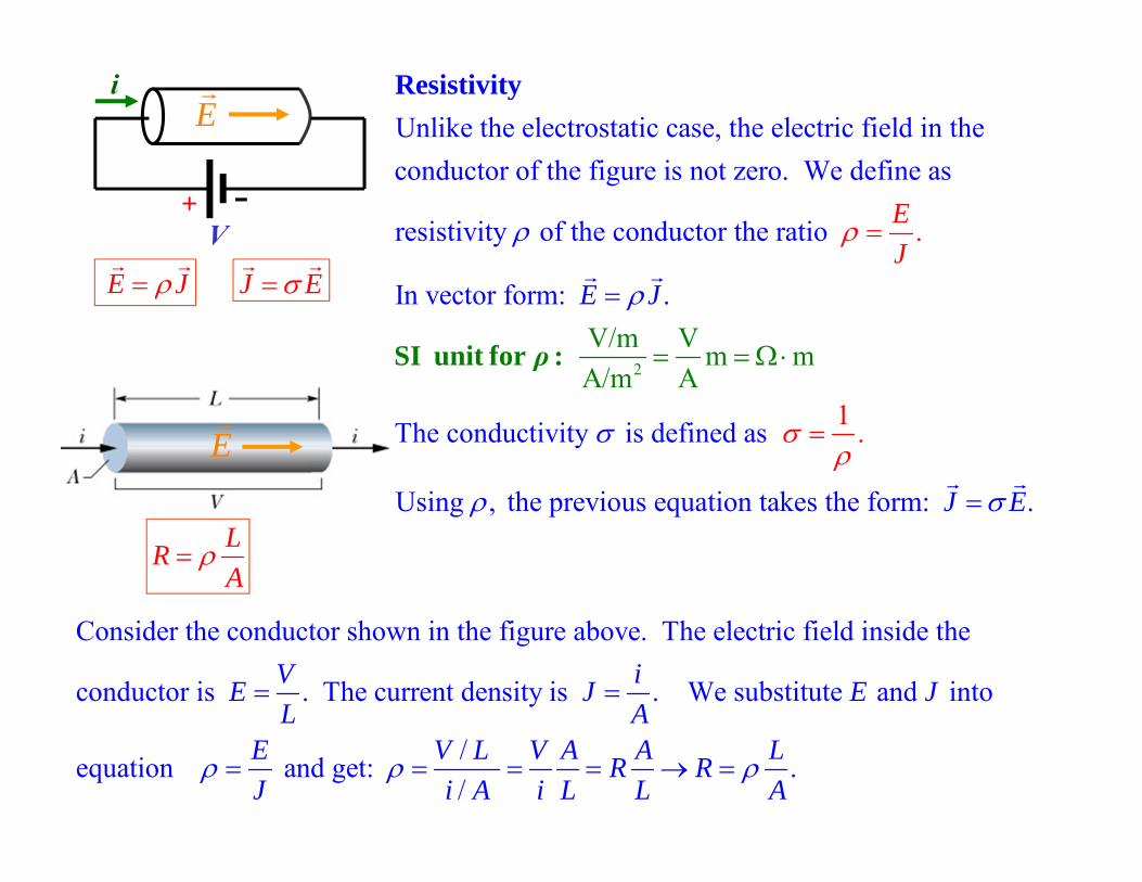
Unlike the electrostatic case, the electric field in theconductor of the figure is not zero. We define as
resistivity of the conductor the ratio
In vector form:
.
.
EJ
E J
SI unit fo
Resistivity
2
1The conductivity is defined as
Using , the
V
p
/m V
re
m mA/m A
vious equation takes the form: .
.
J E
r :
ρ
Consider the conductor shown in the figure above. The electric field inside the
conductor is . The current density is . We substitute and into
/ equation and get: /
V iE J E JL A
E V L VJ i A
.A A LR Ri L L A
LRA
E J
J E
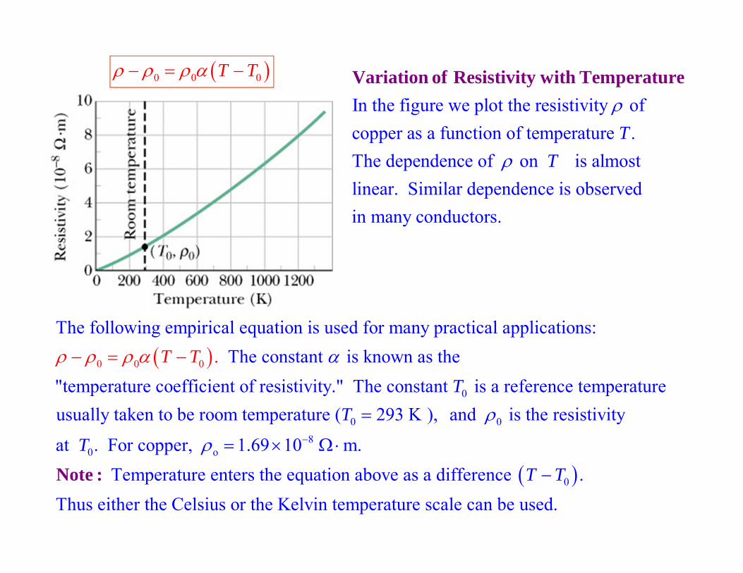
In the figure we plot the resistivity ofcopper as a function of temperature . The dependence of on is almost linear. Similar dependence is observe
TT
Variation of Resistivity with Temperature
din many conductors.
0
0
0 0
The following empirical equation is used for many practical applications: The constant is known as the
"temperature coefficient of resistivity." The constant is a reference tempera.
tT
TT
0 08
0 o
0
ureusually taken to be room temperature ( 293 K ), and is the resistivity
at . For copper, 1.69 10 m. Temperature enters the equation above as a difference .
Thus either the
T
TT T
Note :Celsius or the Kelvin temperature scale can be used.
0 0 0T T
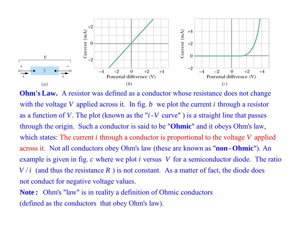
A resistor was defined as a conductor whose resistance does not change with the voltage applied across it. In fig. we plot the current through a resistor as a function of . The pl
V b iV
Ohm's Law.
ot (known as the " - curve" ) is a straight line that passes through the origin. Such a conductor is said to be " " and it obeys Ohm's law, whic The current through ah st conductor is proates:
i
i
VOhmic
Not all conductors obey Ohm's law (these are known as " "). An example is given in fig.
portional to the
where we plot versus for a semiconductor diod
voltage applied across it.
e. Tc i V
Vnon - Ohmic
he ratio/ (and thus the resistance ) is not constant. As a matter of fact, the diode does
not conduct for negative voltage values. Ohm's "law" is in reality a definition of Ohmic conducto
V i R
Note : rs(defined as the conductors that obey Ohm's law).
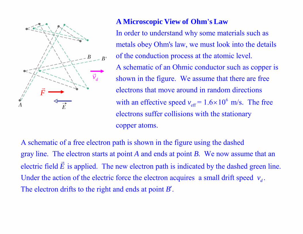
In order to understand why some materials such asmetals obey Ohm's law, we must look into the detailsof the conduction process at the atomic level. A schematic of an O
A Microscopic View of Ohm's Law
6eff
hmic conductor such as copper isshown in the figure. We assume that there are free electrons that move around in random directionswith an effective speed = 1.6 10 m/s. The freeelectrons suffer
v
collisions with the stationary copper atoms.
A schematic of a free electron path is shown in the figure using the dashedgray line. The electron starts at point and ends at point . We now assume that an
electric field is applied. The new
A B
E
electron path is indicated by the dashed green line.Under the action of the electric force the electron acquires a small drift speed . The electron drifts to the right and ends at point .
dvB
F
dv
F
dv
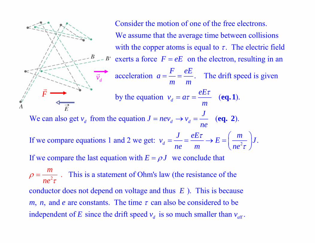
Consider the motion of one of the free electrons.We assume that the average time between collisions with the copper atoms is equal to . The electric fieldexerts a force on the electron, resulF eE
ting in an
acceleration . The drift speed is given
by the equation ( ). d
F eEam m
eEv am
eq. 1
2
2
We can also get from the equation ( ).
If we compare equations 1 and 2 we get: .
If we compare the last equation with we conclude
.
t
hat
d d d
d
Jv J nev vne
J eE mv E Jne m ne
E Jm
ne
eq. 2
This is a statement of Ohm's law (the resistance of the
conductor does not depend on voltage and thus ). This is because , , and are constants. The time can also be considered to be
ind p
e en
Em n e
effdent of since the drift speed is so much smaller than .dE v v
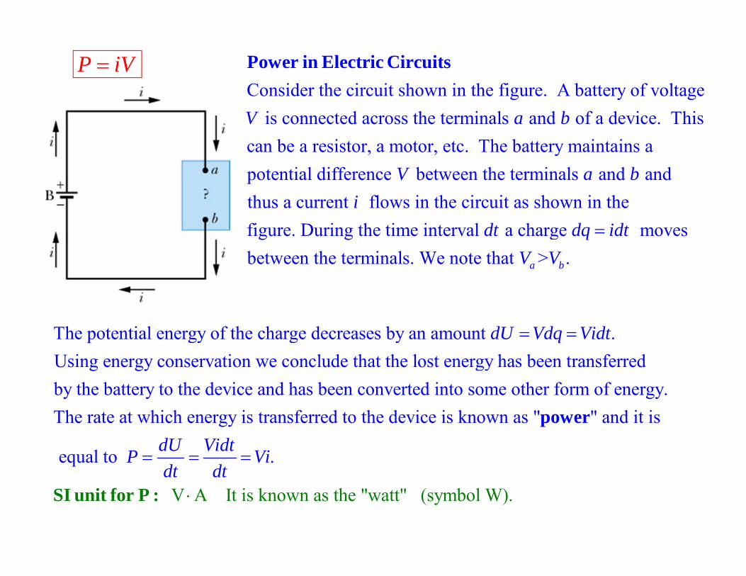
Consider the circuit shown in the figure. A battery of voltage is connected across the terminals and of a device. This
can be a resistor, a motor, etc. The battery mV a b
Power in Electric Circuits
aintains apotential difference between the terminals and and thus a current flows in the circuit as shown in thefigure. During the time interval a charge movesbetween the terminals
V a bi
dt dq idt. We note that > . a bV V
The potential energy of the charge decreases by an amount .Using energy conservation we conclude that the lost energy has been transferred by the battery to the device and has been converte
dU Vdq Vidt
d into some other form of energy.The rate at which energy is transferred to the device is k
V A It is known as the "watt" (s
nown as " " and it is
equal to .
ym
dU VidtP Vidt dt
p
SI unit for P :
ower
bol W).
P iV
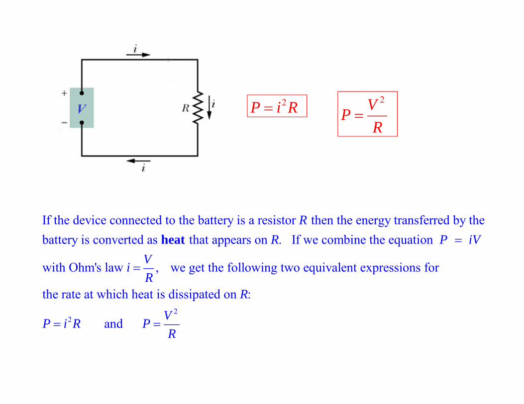
If the device connected to the battery is a resistor then the energy transferred by the battery is converted as that appears on . If we combine the equation
with Ohm's law , we
RR P iV
ViR
heat
22
get the following two equivalent expressions for
the rate at which heat is dissipated on :
and
RVP i R PR
V 2P i R2VP
R