LDTC LAB Series Instrument User Guide
31
USER GUIDE Laboratory Series Laser Diode Driver & Temperature Controller — with IntelliTune ® e Pb RoHS Compliant Applies to Product Revisions A - D © April 2021 ORDERING INFORMATION PART NUMBER DESCRIPTION LD2TC5 LAB 2 A, 10 V Laser Diode Driver 5 A, 15 V Temperature Controller LD5TC10 LAB 5 A, 10 V Laser Diode Driver 10 A, 15 V Temperature Controller LDTC INTLK KIT One included with each instrument BNC Terminator 50 Ω DB15 Male Connector Kit (LD Type A/B) DB15 Female Connector Kit (LD Type C) TC/SENSOR MATING D-SUB One included with each instrument TE/RH/Sensor Male DB15+2 Connector Kit WCB407 TE/RH/Sensor DB15+2 Cable WCB408 LD Type A/B DB15 Cable WCB409 LD Type C DB15 Cable WCB319 TC to LD Mount Cable WCB326 Type A/B Laser to LD Mount Cable WCB327 Type C Laser to LD Mount Cable THERMISTORS Various Thermistors Available LDMOUNT-5A Butterfly Laser Diode Mount CONTENTS GENERAL OVERVIEW 2 SAFETY 3 QUICK CONNECT GUIDE 4 PIN DESCRIPTIONS 6 ELECTRICAL SPECIFICATIONS 7 THEORY OF OPERATION 9 INSTRUMENT OVERVIEW 9 GENERAL OPERATING INSTRUCTIONS 12 TC OPERATING INSTRUCTIONS 17 LD OPERATING INSTRUCTIONS 20 TROUBLESHOOTING 23 ERROR MESSAGES 25 ADDITIONAL TECHNICAL NOTES 27 MECHANICAL SPECIFICATIONS 28 CABLING SPECIFICATIONS 28 WARRANTY & CERTIFICATION 31 B Laser Type A Laser Type C Laser Type R T AD590 LM335 RTD
Transcript of LDTC LAB Series Instrument User Guide
USER GUIDELaboratory Series
Laser Diode Driver & Temperature Controller — with IntelliTune®
ePb
RoHS Com
plia
nt
Applies to Product Revisions A - D© April 2021
ORDERING INFORMATIONPART NUMBER DESCRIPTION
LD2TC5 LAB 2 A, 10 V Laser Diode Driver 5 A, 15 V Temperature Controller
LD5TC10 LAB 5 A, 10 V Laser Diode Driver 10 A, 15 V Temperature Controller
LDTC INTLK KITOne included with each instrumentBNC Terminator 50 ΩDB15 Male Connector Kit (LD Type A/B)DB15 Female Connector Kit (LD Type C)
TC/SENSOR MATING D-SUB
One included with each instrumentTE/RH/Sensor Male DB15+2 Connector Kit
WCB407 TE/RH/Sensor DB15+2 Cable
WCB408 LD Type A/B DB15 Cable
WCB409 LD Type C DB15 Cable
WCB319 TC to LD Mount Cable
WCB326 Type A/B Laser to LD Mount Cable
WCB327 Type C Laser to LD Mount Cable
THERMISTORS Various Thermistors Available
LDMOUNT-5A Butterfly Laser Diode Mount
CONTENTSGENERAL OVERVIEW 2SAFETY 3QUICK CONNECT GUIDE 4PIN DESCRIPTIONS 6ELECTRICAL SPECIFICATIONS 7THEORY OF OPERATION 9INSTRUMENT OVERVIEW 9GENERAL OPERATING INSTRUCTIONS 12TC OPERATING INSTRUCTIONS 17LD OPERATING INSTRUCTIONS 20TROUBLESHOOTING 23ERROR MESSAGES 25ADDITIONAL TECHNICAL NOTES 27MECHANICAL SPECIFICATIONS 28CABLING SPECIFICATIONS 28WARRANTY & CERTIFICATION 31
BLaser Type
A
Laser Type
CLaser Type
RT AD590 LM335RTD
2
GENERAL OVERVIEWFEATURES
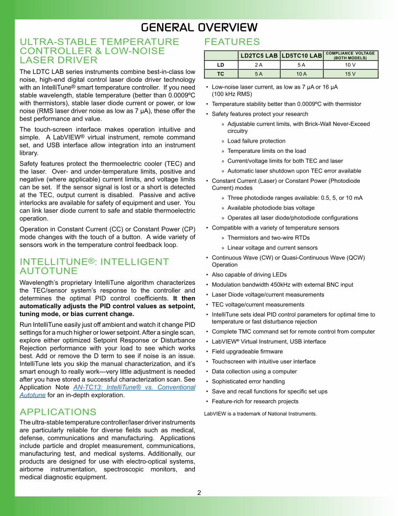
LD2TC5 LAB LD5TC10 LAB COMPLIANCE VOLTAGE (BOTH MODELS)
LD 2 A 5 A 10 V
TC 5 A 10 A 15 V
• Low-noise laser current, as low as 7 μA or 16 μA (100 kHz RMS)
• Temperature stability better than 0.0009ºC with thermistor• Safety features protect your research
» Adjustable current limits, with Brick-Wall Never-Exceed circuitry
» Load failure protection » Temperature limits on the load » Current/voltage limits for both TEC and laser » Automatic laser shutdown upon TEC error available
• Constant Current (Laser) or Constant Power (Photodiode Current) modes
» Three photodiode ranges available: 0.5, 5, or 10 mA » Available photodiode bias voltage » Operates all laser diode/photodiode configurations
• Compatible with a variety of temperature sensors » Thermistors and two-wire RTDs » Linear voltage and current sensors
• Continuous Wave (CW) or Quasi-Continuous Wave (QCW) Operation
• Also capable of driving LEDs• Modulation bandwidth 450kHz with external BNC input• Laser Diode voltage/current measurements• TEC voltage/current measurements• IntelliTune sets ideal PID control parameters for optimal time to
temperature or fast disturbance rejection• Complete TMC command set for remote control from computer• LabVIEW® Virtual Instrument, USB interface• Field upgradeable firmware• Touchscreen with intuitive user interface • Data collection using a computer• Sophisticated error handling• Save and recall functions for specific set ups• Feature-rich for research projects
LabVIEW is a trademark of National Instruments.
ULTRA-STABLE TEMPERATURE CONTROLLER & LOW-NOISE LASER DRIVERThe LDTC LAB series instruments combine best-in-class low noise, high-end digital control laser diode driver technology with an IntelliTune® smart temperature controller. If you need stable wavelength, stable temperature (better than 0.0009ºC with thermistors), stable laser diode current or power, or low noise (RMS laser driver noise as low as 7 µA), these offer the best performance and value.The touch-screen interface makes operation intuitive and simple. A LabVIEW® virtual instrument, remote command set, and USB interface allow integration into an instrument library.Safety features protect the thermoelectric cooler (TEC) and the laser. Over- and under-temperature limits, positive and negative (where applicable) current limits, and voltage limits can be set. If the sensor signal is lost or a short is detected at the TEC, output current is disabled. Passive and active interlocks are available for safety of equipment and user. You can link laser diode current to safe and stable thermoelectric operation.Operation in Constant Current (CC) or Constant Power (CP) mode changes with the touch of a button. A wide variety of sensors work in the temperature control feedback loop.
INTELLITUNE®: INTELLIGENT AUTOTUNEWavelength’s proprietary IntelliTune algorithm characterizes the TEC/sensor system’s response to the controller and determines the optimal PID control coefficients. It then automatically adjusts the PID control values as setpoint, tuning mode, or bias current change.Run IntelliTune easily just off ambient and watch it change PID settings for a much higher or lower setpoint. After a single scan, explore either optimized Setpoint Response or Disturbance Rejection performance with your load to see which works best. Add or remove the D term to see if noise is an issue. IntelliTune lets you skip the manual characterization, and it’s smart enough to really work—very little adjustment is needed after you have stored a successful characterization scan. See Application Note AN-TC13: IntelliTune® vs. Conventional Autotune for an in-depth exploration.
APPLICATIONSThe ultra-stable temperature controller/laser driver instruments are particularly reliable for diverse fields such as medical, defense, communications and manufacturing. Applications include particle and droplet measurement, communications, manufacturing test, and medical systems. Additionally, our products are designed for use with electro-optical systems, airborne instrumentation, spectroscopic monitors, and medical diagnostic equipment.
3
SAFETYDEFINITIONS
CHASSIS GROUND Symbol
CAUTION: A condition that has the potential to cause damage to property or instrument.
WARNING: A condition that has the potential to cause bodily harm or death.
CAUTIONSThe LDTC LAB instrument has no user-serviceable parts. Other than the fuses, the LDTC LAB instrument is not designed to be maintained by the user nor does it contain any parts that can be repaired by the user. All maintenance and repairs must be performed by Wavelength or the warranty will be void. Use a soft cloth to remove dust from the LDTC LAB instrument. Do not expose the LDTC LAB instrument to any liquids, sprays, or solvents. To avoid electrical shock, unplug the power cord before cleaning the instrument.
Before connecting to the power source, make sure the correct cables for your area are set.
WARNINGSPosition the LDTC LAB instrument so that access to the Main Power On/Off switch on the back panel is easily accessed.
Do not use the LDTC LAB instrument if there is evidence of damage from shipping; damaged equipment can present significant safety hazards. If you suspect the LDTC LAB instrument is damaged, contact Wavelength technical support before attempting to operate the instrument.To avoid electrical shock, use the recommended earth-grounded power cables and properly earth-grounded, 3-prong receptacles only. Failure to follow this precaution can result in severe injury.The instrument may not be operated at measuring category II, III, and IV mains power circuits. In accordance with EN 601010-1:2010, the instrument has been designed without a rated measuring category and may only be used at direct voltage circuits with up to 240 VAC without transient overvoltagesOperating safety is no longer assured in the event of modification or alteration. The instrument may only be opened by authorized service technicians. Never operate the instrument at a higher voltage than specified in the technical data. The instrument may otherwise be destroyed or permanently damaged.
To avoid injury, do not tell the engineers how to do their jobs. Let them muddle through until they decide to read the User Guide.
GENERAL• Observe all Cautions and Warnings both in the User Guide and
on the instrument.• This instrument is designed to be safe to at least the following
conditions: indoor use, 6500 ft (2000 m), 80% maximum relative humidity for temperatures up to 31ºC and decreasing linearly to 50% relative humidity at 50ºC, transient overvoltages to Overvoltage Category 2, and environmental conditions to Pollution Degree 2.
• Use the LDTC LAB instrument as specified in this guide. If not, the protection provided by this instrument may be impaired and the warranty will be voided.
• The LDTC LAB instrument is intended to be used to control thermoelectrics, resistive heaters, laser diodes and other similar equipment. Please contact Wavelength Electronics for other possible applications.
• The LDTC LAB instrument must not be operated in explosion endangered environments.
• The equipment is not protected against liquid spills. Do not install where chemicals are used or where liquids could be spilled into the unit.
• The safety of any system that incorporates the use of the LDTC LAB series instrument is the sole responsibility of the system assembler. This includes assembly, mounting, location, special ambient or application conditions, and connections within the system.
• Operating outside of the conditions specified in the User Guide are not recommended for safety reasons.
• Proper setup in the end user’s environment includes: » Adequately sized thermoelectric and heatsink to properly
manage the heat dissipated by the load. » Securely mounted temperature sensor for accurate
temperature control. » Correct connection of the thermoelectric and laser. » Use of the ACTIVE LOCK connection to protect the load.
POWER CORDS• The power cord acts as the power disconnecting device between
the AC mains and LDTC LAB instrument.• This equipment is grounded through the AC power cord
grounding conductor.• Use only the earth-grounded power cords that are
recommended in this user guide.• Route power cords and other cables so that they cannot be
damaged.• Position the LDTC LAB instrument in a location that makes it
easy to quickly disconnect the power cord.• To avoid fire hazard, use only the specified power cords with the
correct grounding, voltage, and current ratings.
FUSES• Disconnect the power to the LDTC LAB instrument before
changing the fuses.• To prevent damage to the LDTC LAB instrument when replacing
fuses, locate and correct the problem that caused the fuse to blow before re-applying power.
• To avoid fire hazard, use only the specified fuse with the correct type number, voltage, and current ratings, and use only the recommended replacement parts.
4
QUICK CONNECT GUIDECONNECT THE POWEROn the back panel, insert the female end of the IEC AC power cable into the Power receptacle and then plug the male end into the AC power source.NOTE: Place the LDTC LAB instrument at least 6” away from any wall to provide adequate ventilation and prevent overheating.
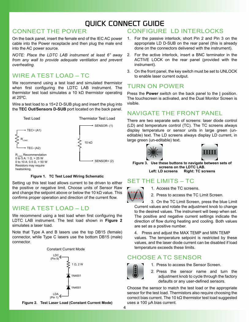
WIRE A TEST LOAD – TC We recommend using a test load and simulated thermistor when first configuring the LDTC LAB instrument. The thermistor test load simulates a 10 kΩ thermistor operating at 25ºC.Wire a test load to a 15+2 D-SUB plug and insert the plug into the TEC Out/Sensors D-SUB port located on the back panel.
10 kΩ
SENSOR- (1)
SENSOR+ (2)
RLOAD Recommendation0 to 5 A: 1 Ω, > 25 W0 to 10 A: 0.5 Ω, > 50 WResistors may require heatsinking.
RLOAD
TEC+ (A1)
TEC- (A2)
Test Load Thermistor Test Load
Figure 1. TC Test Load Wiring Schematic
Setting up this test load allows current to be driven to either the positive or negative limit. Choose units of Sensor Raw and change the setpoint above or below the 10 kΩ value. This confirms proper operation and direction of the current flow.
WIRE A TEST LOAD – LDWe recommend using a test load when first configuring the LDTC LAB instrument. The test load shown in Figure 2 simulates a laser load.Note that Type A and B lasers use the top DB15 (female) connector, while Type C lasers use the bottom DB15 (male) connector.
1N4001
1N4001
LDC(Pin 9)
LDA(Pin 1)
1 Ω, 2 W
Constant Current Mode
Figure 2. Test Laser Load (Constant Current Mode)
CONFIGURE LD INTERLOCKS1. For the passive interlock, short Pin 2 and Pin 3 on the
appropriate LD D-SUB on the rear panel (this is already done on the connectors delivered with the instrument).
2. For the active interlock, insert a BNC terminator in the ACTIVE LOCK on the rear panel (provided with the instrument).
3. On the front panel, the key switch must be set to UNLOCK to enable laser current output.
TURN ON POWERPress the Power switch on the back panel to the | position. The touchscreen is activated, and the Dual Monitor Screen is visible.
NAVIGATE THE FRONT PANELThere are two separate sets of screens: laser diode control (LD) and temperature control (TC). The TC screens always display temperature or sensor units in large green (un-editable) text. The LD screens always display LD current, in large green (un-editable) text.
Figure 3. Use these buttons to navigate between sets of screens on the LDTC LAB.
Left: LD screens Right: TC screens
SET THE LIMITS – TC 1. Access the TC screens.2. Press to access the TC Limit Screen.3. On the TC Limit Screen, press the blue Limit
Current values and rotate the adjustment knob to change to the desired values. The instrument will beep when set. The positive and negative current settings indicate the direction of flow during heating and cooling. Both values are set as a positive number.4. Press and adjust the MAX TEMP and MIN TEMPvalues. The temperature setpoint is restricted by these values, and the laser diode current can be disabled if load temperature exceeds these limits.
CHOOSE A TC SENSOR1. Press to access the Sensor Screen.2. Press the sensor name and turn the
adjustment knob to cycle through the factory defaults or any user-defined sensors.
Choose the sensor to match the test load or the appropriate sensor for the test load. Thermistors also require choosing the correct bias current. The 10 kΩ thermistor test load suggested uses a 100 µA bias current.
5
ADJUST TEMPERATURE SETPOINT
1. Press to access the TC Control Screen.2. Press the blue Setpoint temperature value and turn the adjustment knob to change it. The instrument will beep when set.
The TC Control Screen is also the location of the PID control parameters and IntelliTune (intelligent autotune) characterization scan. The PID values are manually editable or can be adjusted automatically via IntelliTune.
ENABLE TC CURRENTPress the TC ENABLE button on the front panel. There is no delay before the button illuminates and the current flows to the thermoelectric.When current to the thermoelectric is enabled, this light will be illuminated blue.Using a 10 kΩ test load, temperature will not stabilize. Current will drive to the positive limit if setpoint temperature is below 25ºC and to the negative limit if setpoint is above 25ºC.
SET THE LIMITS – LD1. Press to access the Laser Diode Driver Control Screen.2. Access the LD Limit Screen, press the blue text to make it editable, then use the adjustment knob to configure the limits as required.If current reaches the set limit, output current will remain at the limit. Output will not be disabled if the limit is reached.
CHOOSE LD CONTROL MODEOn the LD Control Screen, choose either Constant Current or Constant Power mode. Pressing the text toggles the selection.It is not editable while LD current is enabled.
CONSTANT CURRENT MODEConstant Current (CC) mode maintains a constant current through the laser. The setpoint corresponds to the current through the laser.
CONSTANT POWER MODEConstant Power (CP) mode maintains a constant current through the monitor photodiode, corresponding to a constant power output. If CP mode is chosen, additional parameters must be set on the Photodiode Screen. The test load will not work in CP mode.
1. Press to access the Photodiode Screen.2. Press the blue text next to "PD Biasing" to
toggle whether the bias voltage for the photodiode is enabled or disabled. See the Photodiode Basics App Note for more detail.
3. Press the blue text next to "PD Range" until the value matches the appropriate current range for the photodiode. The available options are 500 μA, 5 mA, and 10 mA.
4. If the transfer function relating photodiode current to optical power is known, this value can be entered using the "Transfer Function" setting. Units are W/mA.
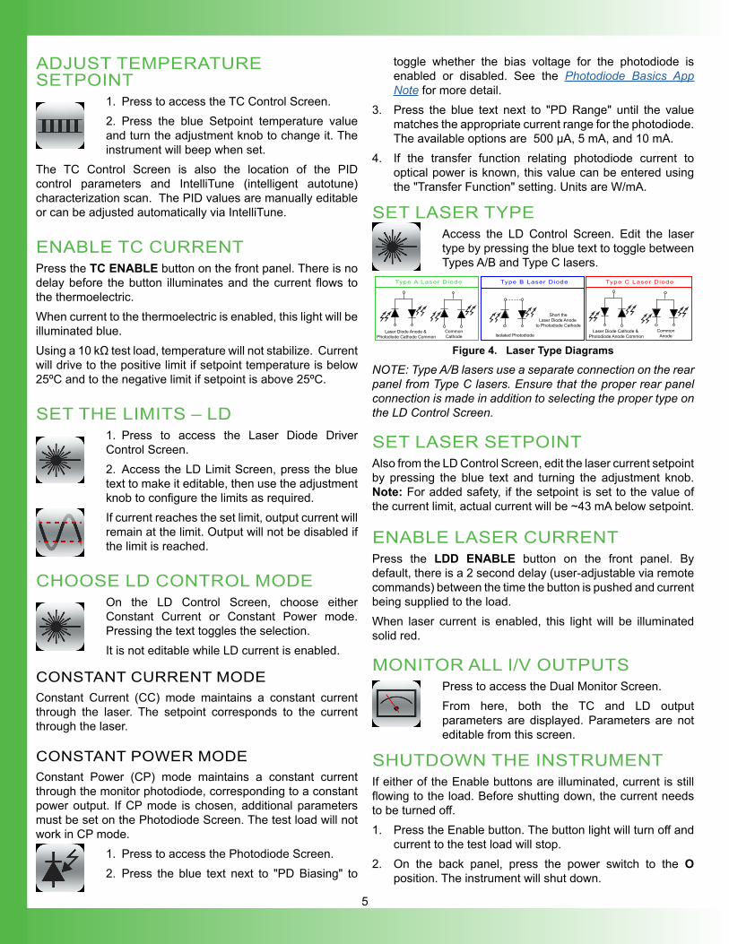
SET LASER TYPEAccess the LD Control Screen. Edit the laser type by pressing the blue text to toggle between Types A/B and Type C lasers.
Type A Laser Diode Type B Laser Diode Type C Laser Diode
CommonCathode
Laser Diode Anode & Photodiode Cathode Common Isolated Photodiode
Short theLaser Diode Anode
to Photodiode CathodeCommon
AnodeLaser Diode Cathode &
Photodiode Anode Common
Figure 4. Laser Type Diagrams
NOTE: Type A/B lasers use a separate connection on the rear panel from Type C lasers. Ensure that the proper rear panel connection is made in addition to selecting the proper type on the LD Control Screen.
SET LASER SETPOINTAlso from the LD Control Screen, edit the laser current setpoint by pressing the blue text and turning the adjustment knob. Note: For added safety, if the setpoint is set to the value of the current limit, actual current will be ~43 mA below setpoint.
ENABLE LASER CURRENTPress the LDD ENABLE button on the front panel. By default, there is a 2 second delay (user-adjustable via remote commands) between the time the button is pushed and current being supplied to the load.When laser current is enabled, this light will be illuminated solid red.
MONITOR ALL I/V OUTPUTSPress to access the Dual Monitor Screen.From here, both the TC and LD output parameters are displayed. Parameters are not editable from this screen.
SHUTDOWN THE INSTRUMENTIf either of the Enable buttons are illuminated, current is still flowing to the load. Before shutting down, the current needs to be turned off.1. Press the Enable button. The button light will turn off and
current to the test load will stop.2. On the back panel, press the power switch to the O
position. The instrument will shut down.
6
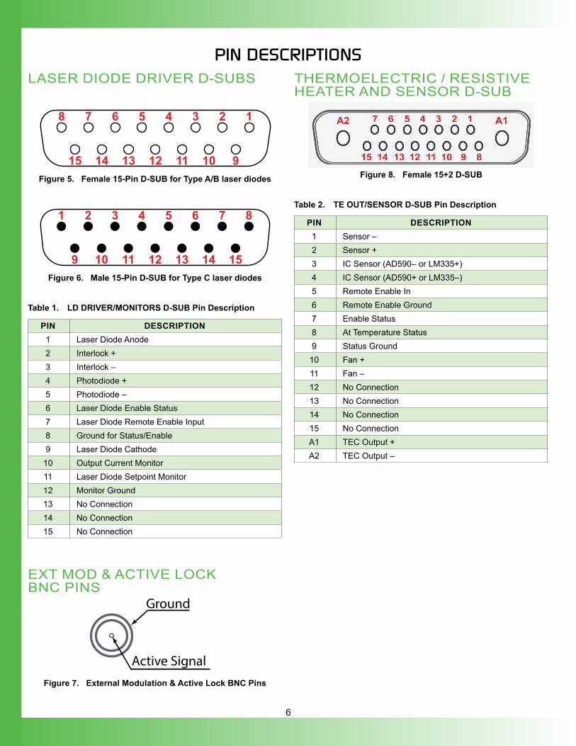
PIN DESCRIPTIONSLASER DIODE DRIVER D-SUBS
15 14 13 12 11 10 9
12345678
Figure 5. Female 15-Pin D-SUB for Type A/B laser diodes
9 10 11 12 13 14 15
87654321
Figure 6. Male 15-Pin D-SUB for Type C laser diodes
Table 1. LD DRIVER/MONITORS D-SUB Pin Description
PIN DESCRIPTION1 Laser Diode Anode2 Interlock +3 Interlock –4 Photodiode +5 Photodiode –6 Laser Diode Enable Status7 Laser Diode Remote Enable Input8 Ground for Status/Enable9 Laser Diode Cathode
10 Output Current Monitor11 Laser Diode Setpoint Monitor12 Monitor Ground13 No Connection14 No Connection15 No Connection
EXT MOD & ACTIVE LOCK BNC PINS
Active Signal
Ground
Figure 7. External Modulation & Active Lock BNC Pins
THERMOELECTRIC / RESISTIVE HEATER AND SENSOR D-SUB
Figure 8. Female 15+2 D-SUB
Table 2. TE OUT/SENSOR D-SUB Pin Description
PIN DESCRIPTION1 Sensor –2 Sensor +3 IC Sensor (AD590– or LM335+)4 IC Sensor (AD590+ or LM335–)5 Remote Enable In6 Remote Enable Ground7 Enable Status8 At Temperature Status9 Status Ground
10 Fan +11 Fan –12 No Connection13 No Connection14 No Connection15 No ConnectionA1 TEC Output +A2 TEC Output –
7
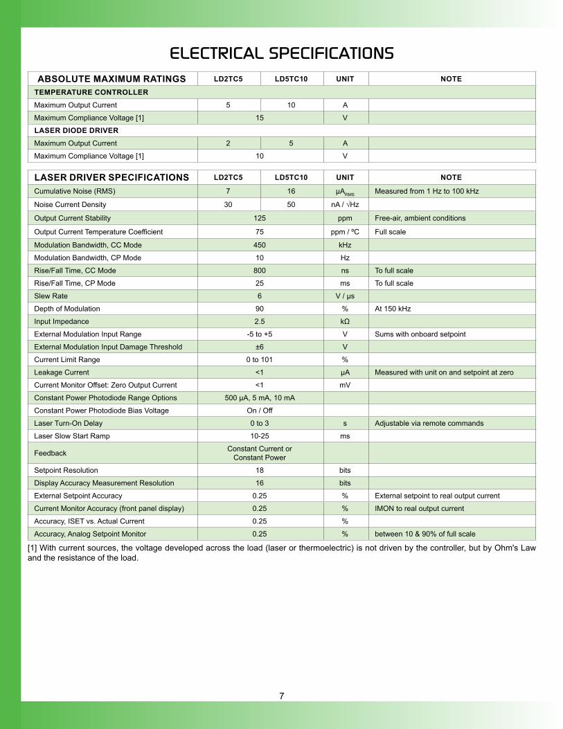
ELECTRICAL SPECIFICATIONS
ABSOLUTE MAXIMUM RATINGS LD2TC5 LD5TC10 UNIT NOTE
TEMPERATURE CONTROLLERMaximum Output Current 5 10 A
Maximum Compliance Voltage [1] 15 V
LASER DIODE DRIVERMaximum Output Current 2 5 A
Maximum Compliance Voltage [1] 10 V
LASER DRIVER SPECIFICATIONS LD2TC5 LD5TC10 UNIT NOTE
Cumulative Noise (RMS) 7 16 μARMS Measured from 1 Hz to 100 kHz
Noise Current Density 30 50 nA / √Hz
Output Current Stability 125 ppm Free-air, ambient conditions
Output Current Temperature Coefficient 75 ppm / ºC Full scale
Modulation Bandwidth, CC Mode 450 kHz
Modulation Bandwidth, CP Mode 10 Hz
Rise/Fall Time, CC Mode 800 ns To full scale
Rise/Fall Time, CP Mode 25 ms To full scale
Slew Rate 6 V / μs
Depth of Modulation 90 % At 150 kHz
Input Impedance 2.5 kΩ
External Modulation Input Range -5 to +5 V Sums with onboard setpoint
External Modulation Input Damage Threshold ±6 V
Current Limit Range 0 to 101 %
Leakage Current <1 μA Measured with unit on and setpoint at zero
Current Monitor Offset: Zero Output Current <1 mV
Constant Power Photodiode Range Options 500 μA, 5 mA, 10 mA
Constant Power Photodiode Bias Voltage On / Off
Laser Turn-On Delay 0 to 3 s Adjustable via remote commands
Laser Slow Start Ramp 10-25 ms
Feedback Constant Current or Constant Power
Setpoint Resolution 18 bits
Display Accuracy Measurement Resolution 16 bits
External Setpoint Accuracy 0.25 % External setpoint to real output current
Current Monitor Accuracy (front panel display) 0.25 % IMON to real output current
Accuracy, ISET vs. Actual Current 0.25 %
Accuracy, Analog Setpoint Monitor 0.25 % between 10 & 90% of full scale
[1] With current sources, the voltage developed across the load (laser or thermoelectric) is not driven by the controller, but by Ohm's Law and the resistance of the load.
8
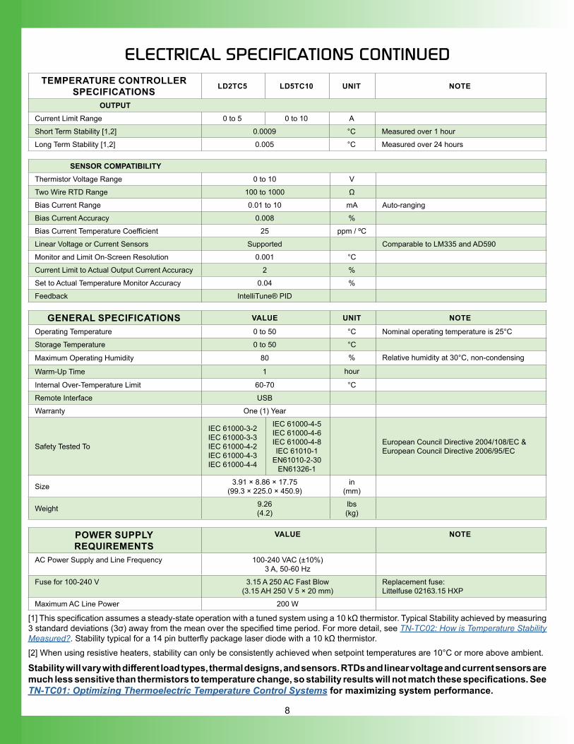
TEMPERATURE CONTROLLER SPECIFICATIONS LD2TC5 LD5TC10 UNIT NOTE
OUTPUTCurrent Limit Range 0 to 5 0 to 10 A
Short Term Stability [1,2] 0.0009 °C Measured over 1 hour
Long Term Stability [1,2] 0.005 °C Measured over 24 hours
SENSOR COMPATIBILITYThermistor Voltage Range 0 to 10 V
Two Wire RTD Range 100 to 1000 Ω
Bias Current Range 0.01 to 10 mA Auto-ranging
Bias Current Accuracy 0.008 %
Bias Current Temperature Coefficient 25 ppm / ºC
Linear Voltage or Current Sensors Supported Comparable to LM335 and AD590
Monitor and Limit On-Screen Resolution 0.001 °C
Current Limit to Actual Output Current Accuracy 2 %
Set to Actual Temperature Monitor Accuracy 0.04 %
Feedback IntelliTune® PID
GENERAL SPECIFICATIONS VALUE UNIT NOTE
Operating Temperature 0 to 50 °C Nominal operating temperature is 25°C
Storage Temperature 0 to 50 °C
Maximum Operating Humidity 80 % Relative humidity at 30°C, non-condensing
Warm-Up Time 1 hour
Internal Over-Temperature Limit 60-70 °C
Remote Interface USB
Warranty One (1) Year
Safety Tested To
IEC 61000-3-2IEC 61000-3-3IEC 61000-4-2IEC 61000-4-3IEC 61000-4-4
IEC 61000-4-5IEC 61000-4-6IEC 61000-4-8IEC 61010-1
EN61010-2-30EN61326-1
European Council Directive 2004/108/EC & European Council Directive 2006/95/EC
Size 3.91 × 8.86 × 17.75(99.3 × 225.0 × 450.9)
in(mm)
Weight 9.26(4.2)
lbs(kg)
POWER SUPPLY REQUIREMENTS
VALUE NOTE
AC Power Supply and Line Frequency 100-240 VAC (±10%) 3 A, 50-60 Hz
Fuse for 100-240 V 3.15 A 250 AC Fast Blow (3.15 AH 250 V 5 × 20 mm)
Replacement fuse:Littelfuse 02163.15 HXP
Maximum AC Line Power 200 W
[1] This specification assumes a steady-state operation with a tuned system using a 10 kΩ thermistor. Typical Stability achieved by measuring 3 standard deviations (3σ) away from the mean over the specified time period. For more detail, see TN-TC02: How is Temperature Stability Measured?. Stability typical for a 14 pin butterfly package laser diode with a 10 kΩ thermistor.[2] When using resistive heaters, stability can only be consistently achieved when setpoint temperatures are 10°C or more above ambient.
Stability will vary with different load types, thermal designs, and sensors. RTDs and linear voltage and current sensors are much less sensitive than thermistors to temperature change, so stability results will not match these specifications. See TN-TC01: Optimizing Thermoelectric Temperature Control Systems for maximizing system performance.
ELECTRICAL SPECIFICATIONS CONTINUED
9
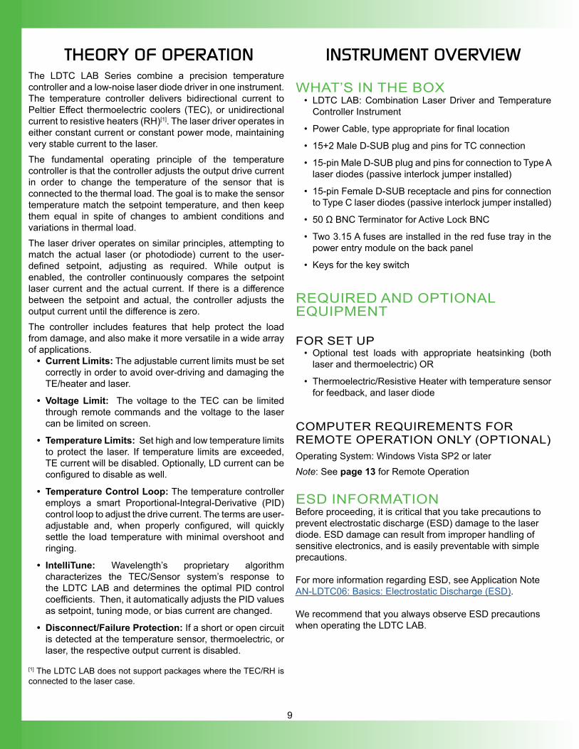
THEORY OF OPERATION The LDTC LAB Series combine a precision temperature controller and a low-noise laser diode driver in one instrument. The temperature controller delivers bidirectional current to Peltier Effect thermoelectric coolers (TEC), or unidirectional current to resistive heaters (RH)[1]. The laser driver operates in either constant current or constant power mode, maintaining very stable current to the laser.The fundamental operating principle of the temperature controller is that the controller adjusts the output drive current in order to change the temperature of the sensor that is connected to the thermal load. The goal is to make the sensor temperature match the setpoint temperature, and then keep them equal in spite of changes to ambient conditions and variations in thermal load.The laser driver operates on similar principles, attempting to match the actual laser (or photodiode) current to the user-defined setpoint, adjusting as required. While output is enabled, the controller continuously compares the setpoint laser current and the actual current. If there is a difference between the setpoint and actual, the controller adjusts the output current until the difference is zero.The controller includes features that help protect the load from damage, and also make it more versatile in a wide array of applications.
• Current Limits: The adjustable current limits must be set correctly in order to avoid over-driving and damaging the TE/heater and laser.
• Voltage Limit: The voltage to the TEC can be limited through remote commands and the voltage to the laser can be limited on screen.
• Temperature Limits: Set high and low temperature limits to protect the laser. If temperature limits are exceeded, TE current will be disabled. Optionally, LD current can be configured to disable as well.
• Temperature Control Loop: The temperature controller employs a smart Proportional-Integral-Derivative (PID) control loop to adjust the drive current. The terms are user-adjustable and, when properly configured, will quickly settle the load temperature with minimal overshoot and ringing.
• IntelliTune: Wavelength’s proprietary algorithm characterizes the TEC/Sensor system’s response to the LDTC LAB and determines the optimal PID control coefficients. Then, it automatically adjusts the PID values as setpoint, tuning mode, or bias current are changed.
• Disconnect/Failure Protection: If a short or open circuit is detected at the temperature sensor, thermoelectric, or laser, the respective output current is disabled.
[1] The LDTC LAB does not support packages where the TEC/RH is connected to the laser case.
INSTRUMENT OVERVIEW
WHAT’S IN THE BOX• LDTC LAB: Combination Laser Driver and Temperature
Controller Instrument
• Power Cable, type appropriate for final location
• 15+2 Male D-SUB plug and pins for TC connection
• 15-pin Male D-SUB plug and pins for connection to Type A laser diodes (passive interlock jumper installed)
• 15-pin Female D-SUB receptacle and pins for connection to Type C laser diodes (passive interlock jumper installed)
• 50 Ω BNC Terminator for Active Lock BNC
• Two 3.15 A fuses are installed in the red fuse tray in the power entry module on the back panel
• Keys for the key switch
REQUIRED AND OPTIONAL EQUIPMENT
FOR SET UP• Optional test loads with appropriate heatsinking (both
laser and thermoelectric) OR
• Thermoelectric/Resistive Heater with temperature sensor for feedback, and laser diode
COMPUTER REQUIREMENTS FOR REMOTE OPERATION ONLY (OPTIONAL)Operating System: Windows Vista SP2 or laterNote: See page 13 for Remote Operation
ESD INFORMATIONBefore proceeding, it is critical that you take precautions to prevent electrostatic discharge (ESD) damage to the laser diode. ESD damage can result from improper handling of sensitive electronics, and is easily preventable with simple precautions.
For more information regarding ESD, see Application NoteAN-LDTC06: Basics: Electrostatic Discharge (ESD).
We recommend that you always observe ESD precautionswhen operating the LDTC LAB.
10
REAR PANELC
AUTI
ON
: N
o us
er s
ervi
ceab
le p
arts
. D
o no
t rem
ove
cove
r.
TE OUT SENSORS
LD TYPE A/B
LD TYPE C USB
FUSE ~F 3.15AH 250 V(5 x 20 mm)
100 - 240 V~3.15 A, 50-60 Hz
CHASSISGND
SERIAL # !
MAX TEC Voltage MAX TEC Current
MAX LDD Voltage MAX LDD Current
EXT MOD
ACTIVE LOCK
6
7
891011
1 2 3 4 5
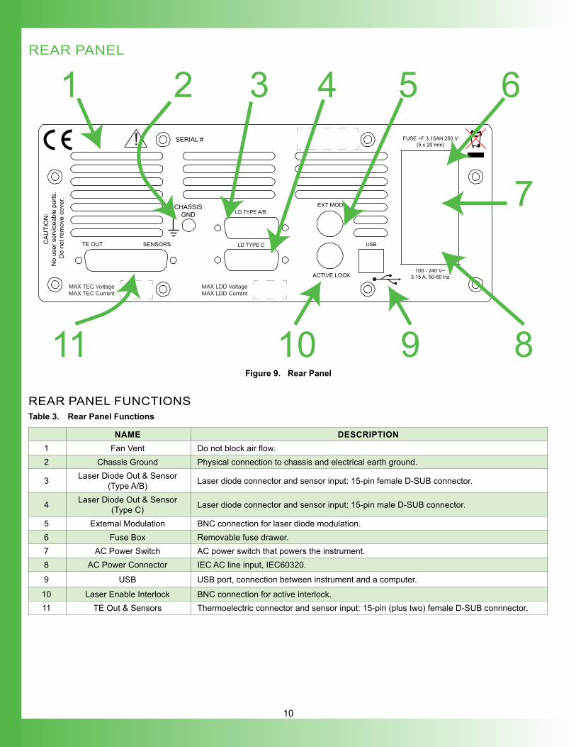
Figure 9. Rear Panel
REAR PANEL FUNCTIONSTable 3. Rear Panel Functions
NAME DESCRIPTION1 Fan Vent Do not block air flow.2 Chassis Ground Physical connection to chassis and electrical earth ground.
3 Laser Diode Out & Sensor (Type A/B) Laser diode connector and sensor input: 15-pin female D-SUB connector.
4 Laser Diode Out & Sensor (Type C) Laser diode connector and sensor input: 15-pin male D-SUB connector.
5 External Modulation BNC connection for laser diode modulation.6 Fuse Box Removable fuse drawer.7 AC Power Switch AC power switch that powers the instrument.8 AC Power Connector IEC AC line input, IEC60320.
9 USB USB port, connection between instrument and a computer.
10 Laser Enable Interlock BNC connection for active interlock.11 TE Out & Sensors Thermoelectric connector and sensor input: 15-pin (plus two) female D-SUB connnector.
11
FRONT PANEL
LDD ENABLE TC ENABLE
Laser Diode & Temperature ControlLD5 TC10 LAB
1 3
52
4
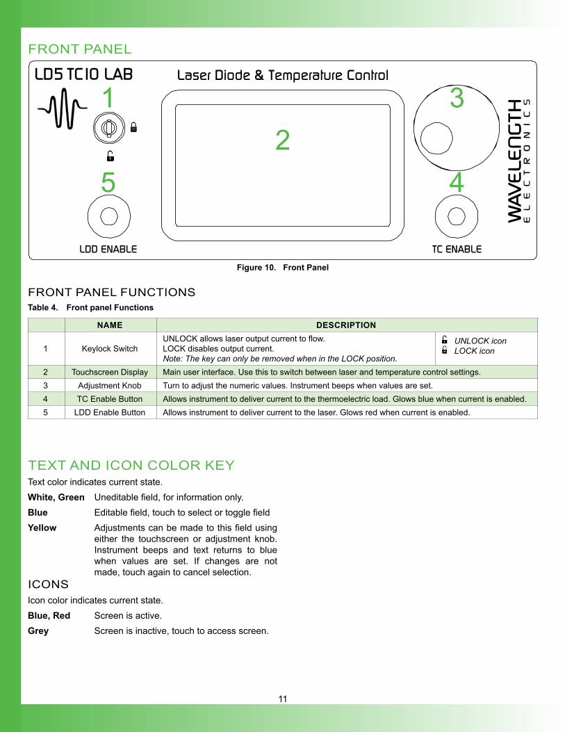
Figure 10. Front Panel
FRONT PANEL FUNCTIONSTable 4. Front panel Functions
NAME DESCRIPTION
1 Keylock SwitchUNLOCK allows laser output current to flow. LOCK disables output current.Note: The key can only be removed when in the LOCK position.
UNLOCK icon LOCK icon
2 Touchscreen Display Main user interface. Use this to switch between laser and temperature control settings.3 Adjustment Knob Turn to adjust the numeric values. Instrument beeps when values are set.4 TC Enable Button Allows instrument to deliver current to the thermoelectric load. Glows blue when current is enabled.5 LDD Enable Button Allows instrument to deliver current to the laser. Glows red when current is enabled.
TEXT AND ICON COLOR KEYText color indicates current state.White, Green Uneditable field, for information only.Blue Editable field, touch to select or toggle field Yellow Adjustments can be made to this field using
either the touchscreen or adjustment knob. Instrument beeps and text returns to blue when values are set. If changes are not made, touch again to cancel selection.
ICONSIcon color indicates current state.Blue, Red Screen is active. Grey Screen is inactive, touch to access screen.
12
GENERAL OPERATING INSTRUCTIONS
Wiring and instrument navigation are followed by instructions specific to the temperature control portion of the LDTC LAB, and instructions discussing the laser driver functionality of the LDTC LAB. Temperature controller (TC) instructions begin on page 17.Laser driver (LD) instructions begin on page 20.
CONNECT THE POWEROn the back panel, insert the female end of the IEC AC power cable into the Power receptacle and then plug the male end into the AC power source.NOTE: Place the LDTC LAB instrument at least 6” away from any wall to provide adequate ventilation and prevent overheating.
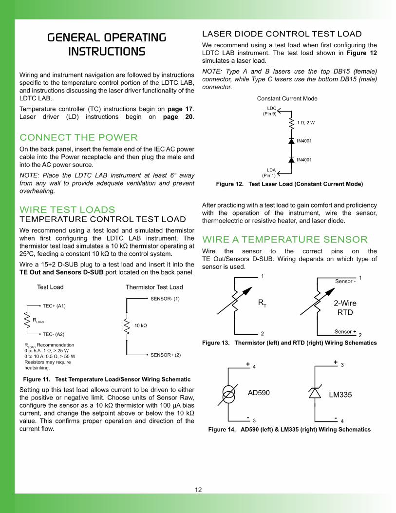
WIRE TEST LOADSTEMPERATURE CONTROL TEST LOADWe recommend using a test load and simulated thermistor when first configuring the LDTC LAB instrument. The thermistor test load simulates a 10 kΩ thermistor operating at 25ºC, feeding a constant 10 kΩ to the control system.Wire a 15+2 D-SUB plug to a test load and insert it into the TE Out and Sensors D-SUB port located on the back panel.
10 kΩ
SENSOR- (1)
SENSOR+ (2)
RLOAD Recommendation0 to 5 A: 1 Ω, > 25 W0 to 10 A: 0.5 Ω, > 50 WResistors may require heatsinking.
RLOAD
TEC+ (A1)
TEC- (A2)
Test Load Thermistor Test Load
Figure 11. Test Temperature Load/Sensor Wiring Schematic
Setting up this test load allows current to be driven to either the positive or negative limit. Choose units of Sensor Raw, configure the sensor as a 10 kΩ thermistor with 100 µA bias current, and change the setpoint above or below the 10 kΩ value. This confirms proper operation and direction of the current flow.
LASER DIODE CONTROL TEST LOADWe recommend using a test load when first configuring the LDTC LAB instrument. The test load shown in Figure 12 simulates a laser load.NOTE: Type A and B lasers use the top DB15 (female) connector, while Type C lasers use the bottom DB15 (male) connector.
1N4001
1N4001
LDC(Pin 9)
LDA(Pin 1)
1 Ω, 2 W
Constant Current Mode
Figure 12. Test Laser Load (Constant Current Mode)
After practicing with a test load to gain comfort and proficiency with the operation of the instrument, wire the sensor, thermoelectric or resistive heater, and laser diode.
WIRE A TEMPERATURE SENSORWire the sensor to the correct pins on the TE Out/Sensors D-SUB. Wiring depends on which type of sensor is used.
1
2
RT
1
2
2-WireRTD
Sensor -
Sensor +
Figure 13. Thermistor (left) and RTD (right) Wiring Schematics
AD590
4
3
+
-
LM335
3
4
+
-Figure 14. AD590 (left) & LM335 (right) Wiring Schematics
13
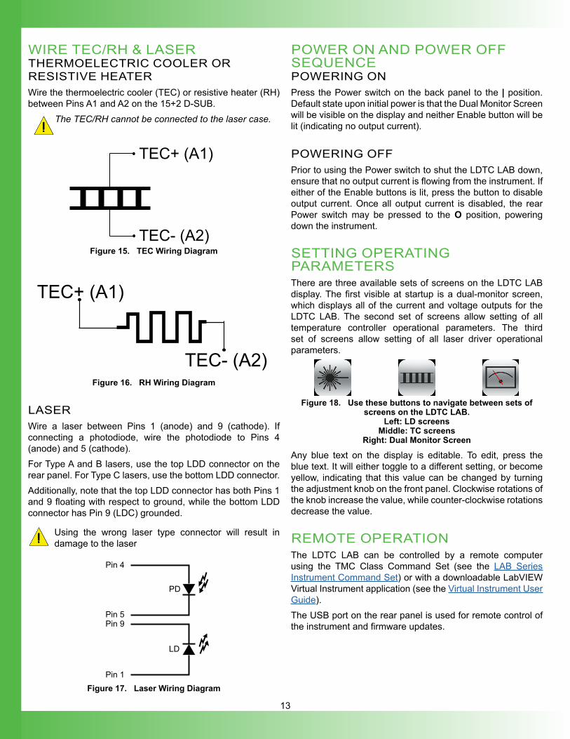
WIRE TEC/RH & LASERTHERMOELECTRIC COOLER OR RESISTIVE HEATERWire the thermoelectric cooler (TEC) or resistive heater (RH) between Pins A1 and A2 on the 15+2 D-SUB.
The TEC/RH cannot be connected to the laser case.
TEC- (A2)
TEC+ (A1)
Figure 15. TEC Wiring Diagram
TEC- (A2)
TEC+ (A1)
Figure 16. RH Wiring Diagram
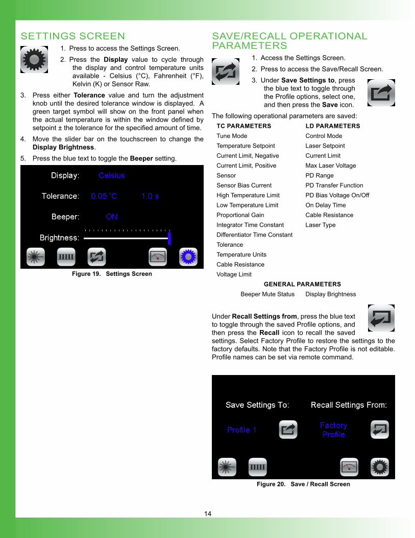
LASERWire a laser between Pins 1 (anode) and 9 (cathode). If connecting a photodiode, wire the photodiode to Pins 4 (anode) and 5 (cathode). For Type A and B lasers, use the top LDD connector on the rear panel. For Type C lasers, use the bottom LDD connector.Additionally, note that the top LDD connector has both Pins 1 and 9 floating with respect to ground, while the bottom LDD connector has Pin 9 (LDC) grounded.
Using the wrong laser type connector will result in damage to the laser
LD
Pin 1
Pin 9Pin 5
Pin 4
PD
Figure 17. Laser Wiring Diagram
POWER ON AND POWER OFF SEQUENCEPOWERING ONPress the Power switch on the back panel to the | position. Default state upon initial power is that the Dual Monitor Screen will be visible on the display and neither Enable button will be lit (indicating no output current).
POWERING OFFPrior to using the Power switch to shut the LDTC LAB down, ensure that no output current is flowing from the instrument. If either of the Enable buttons is lit, press the button to disable output current. Once all output current is disabled, the rear Power switch may be pressed to the O position, powering down the instrument.
SETTING OPERATING PARAMETERSThere are three available sets of screens on the LDTC LAB display. The first visible at startup is a dual-monitor screen, which displays all of the current and voltage outputs for the LDTC LAB. The second set of screens allow setting of all temperature controller operational parameters. The third set of screens allow setting of all laser driver operational parameters.
Figure 18. Use these buttons to navigate between sets of screens on the LDTC LAB.
Left: LD screens Middle: TC screens
Right: Dual Monitor Screen
Any blue text on the display is editable. To edit, press the blue text. It will either toggle to a different setting, or become yellow, indicating that this value can be changed by turning the adjustment knob on the front panel. Clockwise rotations of the knob increase the value, while counter-clockwise rotations decrease the value.
REMOTE OPERATIONThe LDTC LAB can be controlled by a remote computer using the TMC Class Command Set (see the LAB Series Instrument Command Set) or with a downloadable LabVIEW Virtual Instrument application (see the Virtual Instrument User Guide).The USB port on the rear panel is used for remote control of the instrument and firmware updates.
14
SETTINGS SCREEN1. Press to access the Settings Screen.2. Press the Display value to cycle through
the display and control temperature units available - Celsius (°C), Fahrenheit (°F), Kelvin (K) or Sensor Raw.
3. Press either Tolerance value and turn the adjustment knob until the desired tolerance window is displayed. A green target symbol will show on the front panel when the actual temperature is within the window defined by setpoint ± the tolerance for the specified amount of time.
4. Move the slider bar on the touchscreen to change the Display Brightness.
5. Press the blue text to toggle the Beeper setting.
Figure 19. Settings Screen
SAVE/RECALL OPERATIONAL PARAMETERS
1. Access the Settings Screen.2. Press to access the Save/Recall Screen.3. Under Save Settings to, press
the blue text to toggle through the Profile options, select one, and then press the Save icon.
The following operational parameters are saved: TC PARAMETERS LD PARAMETERSTune Mode Control ModeTemperature Setpoint Laser SetpointCurrent Limit, Negative Current LimitCurrent Limit, Positive Max Laser VoltageSensor PD RangeSensor Bias Current PD Transfer FunctionHigh Temperature Limit PD Bias Voltage On/OffLow Temperature Limit On Delay TimeProportional Gain Cable ResistanceIntegrator Time Constant Laser TypeDifferentiator Time ConstantToleranceTemperature UnitsCable ResistanceVoltage Limit
GENERAL PARAMETERSBeeper Mute Status Display Brightness
Under Recall Settings from, press the blue text to toggle through the saved Profile options, and then press the Recall icon to recall the saved settings. Select Factory Profile to restore the settings to the factory defaults. Note that the Factory Profile is not editable. Profile names can be set via remote command.
Figure 20. Save / Recall Screen
15
ENABLE/DISABLE OUTPUT CURRENTOn the front panel, the LDD Enable and TC Enable buttons dictate whether or not output current is enabled. To enable either the LD or the TC current, push the corresponding button on the front panel. If output current is enabled, the LED will be lit (red for laser, blue for temperature control). There is no time delay before temperature output current is enabled after pushing the button. By default, there is a 2 second delay after pushing the LDD Enable button for current to be output to the laser.To disable current, press the corresponding Enable button again. Once the button is pushed, current will immediately disable, and the LED will become dark.
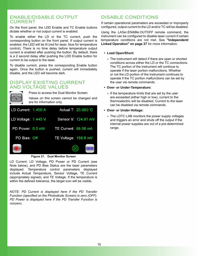
DISPLAY EXISTING CURRENT AND VOLTAGE VALUES
Press to access the Dual Monitor Screen.Values on this screen cannot be changed and are for information only.
Figure 21. Dual Monitor Screen
LD Current, LD Voltage, PD Power or PD Current (see Note below), and PD Bias Status are the laser parameters displayed. Temperature control parameters displayed include Actual Temperature, Sensor Voltage, TE Current (appropriately signed), and TE Voltage. If the temperature is within the defined tolerance, the target icon will be visible.
NOTE: PD Current is displayed here if the PD Transfer Function (specified on the Photodiode Screen) is zero (OFF). PD Power is displayed here if the PD Transfer Function is nonzero.
DISABLE CONDITIONSIf certain operational parameters are exceeded or improperly configured, output current to the LD and/or TC will be disabled.Using the LASer:ENABle:OUTOFF remote command, the instrument can be configured to disable laser current if certain temperature conditions are not met. See "Independent/Linked Operation" on page 27 for more information.
• Load Open/Short:
» The instrument will detect if there are open or shorted conditions across either the LD or the TC connections. The TC portion of the instrument will continue to operate if the laser portion malfunctions. Whether or not the LD portion of the instrument continues to operate if the TC portion malfunctions can be set by the user via remote commands.
• Over- or Under-Temperature:
» If the temperature limits that are set by the user are exceeded (either high or low), current to the thermoelectric will be disabled. Current to the laser can be disabled via remote commands.
• Over- or Under-Voltage:
» The LDTC LAB monitors the power supply voltages and triggers an error and shuts off the output if the internal power supplies are out of a pre-determined range.
16
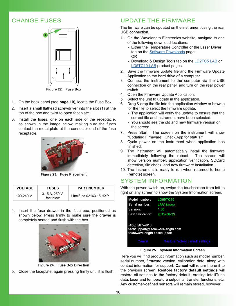
CHANGE FUSES
Figure 22. Fuse Box
1. On the back panel (see page 10), locate the Fuse Box. 2. Insert a small flathead screwdriver into the slot (1) at the
top of the box and twist to open faceplate. 3. Install the fuses, one on each side of the receptacle,
as shown in the image below, making sure the fuses contact the metal plate at the connector end of the fuse receptacle.
Figure 23. Fuse Placement
VOLTAGE FUSES PART NUMBER
100-240 V 3.15 A, 250 V, fast blow Littelfuse 02163.15 HXP
4. Insert the fuse drawer in the fuse box, positioned as shown below. Press firmly to make sure the drawer is completely seated and flush with the box.
Figure 24. Fuse Box Direction
5. Close the faceplate, again pressing firmly until it is flush.
UPDATE THE FIRMWAREThe firmware can be updated on the instrument using the rear USB connection. 1. On the Wavelength Electronics website, navigate to one
of the following download locations: » Either the Temperature Controller or the Laser Driver tab on the Software Downloads page.OR
» Download & Design Tools tab on the LD2TC5 LAB or LD5TC10 LAB product pages.
2. Save the firmware update file and the Firmware Update Application to the hard drive of a computer.
3. Connect the instrument to the computer via the USB connection on the rear panel, and turn on the rear power switch.
4. Open the Firmware Update Application.5. Select the unit to update in the application.6. Drag & drop the file into the application window or browse
for the file to select the firmware update. » The application will verify the update to ensure that the correct file and instrument have been selected.
» You should see the old and new firmware version on the screen.
7. Press Start. The screen on the instrument will show "Updating Firmware. Check App for status."
8. Cycle power on the instrument when application has finished.
9. The instrument will automatically install the firmware immediately following the reboot. The screen will show version number, application verification, SDCard detection, file check, and new firmware installation.
10. The instrument is ready to run when returned to home (remote) screen.
SYSTEM INFORMATIONWith the power switch on, swipe the touchscreen from left to right on any screen to show the System Information screen.
Figure 25. System Information Screen
Here you will find product information such as model number, serial number, firmware version, calibration date, along with contact information for support. Cancel will return the unit to the previous screen. Restore factory default settings will restore all settings to the factory default, erasing IntelliTune data, laser and temperature setpoints, transfer functions, etc. Any customer-defined sensors will remain stored, however.
17
TC OPERATING INSTRUCTIONSThe LDTC LAB does not support TEC/RH that are connected to the laser case.
ACCESS THE TC SCREENSEnsure that the instrument is on the TC Screens by pressing the TC Screen button if the TC Screen is not active.
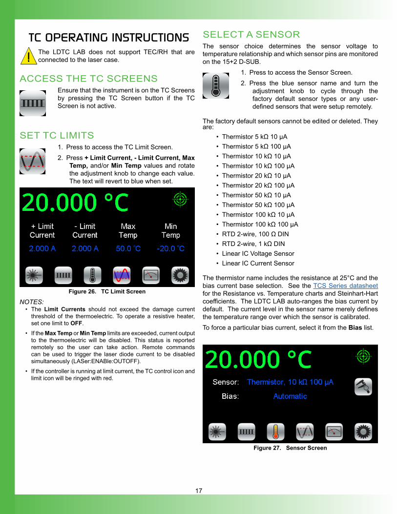
SET TC LIMITS1. Press to access the TC Limit Screen.2. Press + Limit Current, - Limit Current, Max
Temp, and/or Min Temp values and rotate the adjustment knob to change each value. The text will revert to blue when set.
Figure 26. TC Limit Screen
NOTES: • The Limit Currents should not exceed the damage current
threshold of the thermoelectric. To operate a resistive heater, set one limit to OFF.
• If the Max Temp or Min Temp limits are exceeded, current output to the thermoelectric will be disabled. This status is reported remotely so the user can take action. Remote commands can be used to trigger the laser diode current to be disabled simultaneously (LASer:ENABle:OUTOFF).
• If the controller is running at limit current, the TC control icon and limit icon will be ringed with red.
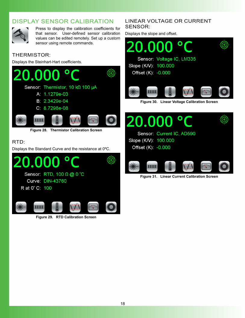
SELECT A SENSORThe sensor choice determines the sensor voltage to temperature relationship and which sensor pins are monitored on the 15+2 D-SUB.
1. Press to access the Sensor Screen.2. Press the blue sensor name and turn the
adjustment knob to cycle through the factory default sensor types or any user-defined sensors that were setup remotely.
The factory default sensors cannot be edited or deleted. They are:
• Thermistor 5 kΩ 10 µA• Thermistor 5 kΩ 100 µA• Thermistor 10 kΩ 10 µA• Thermistor 10 kΩ 100 µA• Thermistor 20 kΩ 10 µA• Thermistor 20 kΩ 100 µA• Thermistor 50 kΩ 10 µA• Thermistor 50 kΩ 100 µA• Thermistor 100 kΩ 10 µA• Thermistor 100 kΩ 100 µA• RTD 2-wire, 100 Ω DIN• RTD 2-wire, 1 kΩ DIN• Linear IC Voltage Sensor• Linear IC Current Sensor
The thermistor name includes the resistance at 25°C and the bias current base selection. See the TCS Series datasheet for the Resistance vs. Temperature charts and Steinhart-Hart coefficients. The LDTC LAB auto-ranges the bias current by default. The current level in the sensor name merely defines the temperature range over which the sensor is calibrated.To force a particular bias current, select it from the Bias list.
Figure 27. Sensor Screen
18
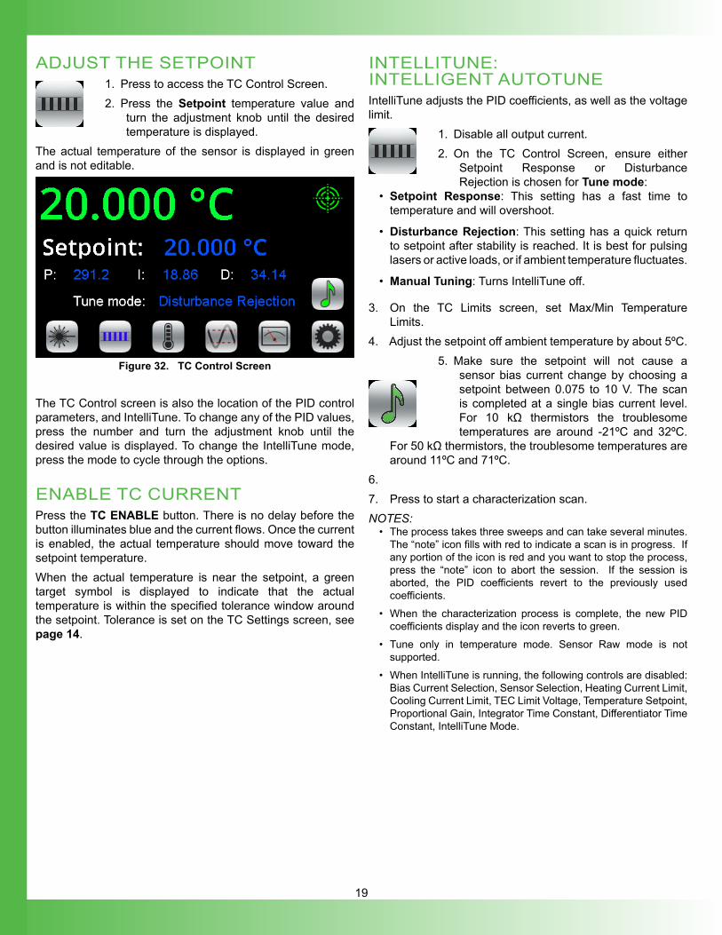
DISPLAY SENSOR CALIBRATIONPress to display the calibration coefficients for that sensor. User-defined sensor calibration values can be edited remotely. Set up a custom sensor using remote commands.
THERMISTOR:Displays the Steinhart-Hart coefficients.
Figure 28. Thermistor Calibration Screen
RTD:Displays the Standard Curve and the resistance at 0ºC.
Figure 29. RTD Calibration Screen
LINEAR VOLTAGE OR CURRENT SENSOR:Displays the slope and offset.
Figure 30. Linear Voltage Calibration Screen
Figure 31. Linear Current Calibration Screen
19
ADJUST THE SETPOINT1. Press to access the TC Control Screen.2. Press the Setpoint temperature value and
turn the adjustment knob until the desired temperature is displayed.
The actual temperature of the sensor is displayed in green and is not editable.
Figure 32. TC Control Screen
The TC Control screen is also the location of the PID control parameters, and IntelliTune. To change any of the PID values, press the number and turn the adjustment knob until the desired value is displayed. To change the IntelliTune mode, press the mode to cycle through the options. ENABLE TC CURRENTPress the TC ENABLE button. There is no delay before the button illuminates blue and the current flows. Once the current is enabled, the actual temperature should move toward the setpoint temperature.When the actual temperature is near the setpoint, a green target symbol is displayed to indicate that the actual temperature is within the specified tolerance window around the setpoint. Tolerance is set on the TC Settings screen, see page 14.
INTELLITUNE: INTELLIGENT AUTOTUNEIntelliTune adjusts the PID coefficients, as well as the voltage limit.
1. Disable all output current.2. On the TC Control Screen, ensure either
Setpoint Response or Disturbance Rejection is chosen for Tune mode:
• Setpoint Response: This setting has a fast time to temperature and will overshoot.
• Disturbance Rejection: This setting has a quick return to setpoint after stability is reached. It is best for pulsing lasers or active loads, or if ambient temperature fluctuates.
• Manual Tuning: Turns IntelliTune off.
3. On the TC Limits screen, set Max/Min Temperature Limits.
4. Adjust the setpoint off ambient temperature by about 5ºC. 5. Make sure the setpoint will not cause a
sensor bias current change by choosing a setpoint between 0.075 to 10 V. The scan is completed at a single bias current level. For 10 kΩ thermistors the troublesome temperatures are around -21ºC and 32ºC.
For 50 kΩ thermistors, the troublesome temperatures are around 11ºC and 71ºC.
6. 7. Press to start a characterization scan. NOTES:
• The process takes three sweeps and can take several minutes. The “note” icon fills with red to indicate a scan is in progress. If any portion of the icon is red and you want to stop the process, press the “note” icon to abort the session. If the session is aborted, the PID coefficients revert to the previously used coefficients.
• When the characterization process is complete, the new PID coefficients display and the icon reverts to green.
• Tune only in temperature mode. Sensor Raw mode is not supported.
• When IntelliTune is running, the following controls are disabled: Bias Current Selection, Sensor Selection, Heating Current Limit, Cooling Current Limit, TEC Limit Voltage, Temperature Setpoint, Proportional Gain, Integrator Time Constant, Differentiator Time Constant, IntelliTune Mode.
20
INTELLITUNE CONTINUOUSLY OPTIMIZESOnce a system is run through the IntelliTune process, the PID coefficents are adjusted as the setpoint, tune mode, or bias current is changed. The IntelliTune setpoint does not need to match the system setpoint if the system setpoint is very high or very low. Run IntelliTune at a setpoint about 5ºC away from ambient. IntelliTune stops if the sensor is changed or the tuning mode is set to Manual Tuning.During an IntelliTune process, the current limits are set to 10% of the initial values. The limit icon glows red frequently. Current limits are restored after the scan is complete.See Application Note AN-TC13: IntelliTune® vs. Conventional Autotune for an in-depth exploration of IntelliTune.
ENABLE, STATUS, & FAN PINS ON THE TE OUT/SENSOR D-SUB
Figure 33. TE OUT/SENSOR 15+2-pin D-SUB
REMOTE ENABLE INPUT (PINS 5 & 6)This is a TTL signal that will override the front panel TC ENABLE button. The default polarity is ENABLE HIGH. Use 0 V to disable the output regardless of the front panel enable button. An internal 100 kΩ pull-up resistor means no external voltage is required for front panel operation with the default polarity. The polarity can be changed by remote command.
ENABLE STATUS (PINS 7 & 9)This is a TTL signal that goes HI when the TC output current is enabled.
AT TEMPERATURE STATUS (PINS 8 & 9)This is a TTL signal that goes HI when the actual temperature is within the window defined by setpoint ± tolerance.
FAN CURRENT DRIVE (PINS 10 & 11)This output will drive 12 V up to 0.5 A to power a fan for airflow across the thermoelectric and load.
LD OPERATING INSTRUCTIONS
ACCESS THE LD SCREENSEnsure that the instrument is on the LD Screens by pressing the LD Screen button if the LD Control Screen (see Figure 35) is not active.
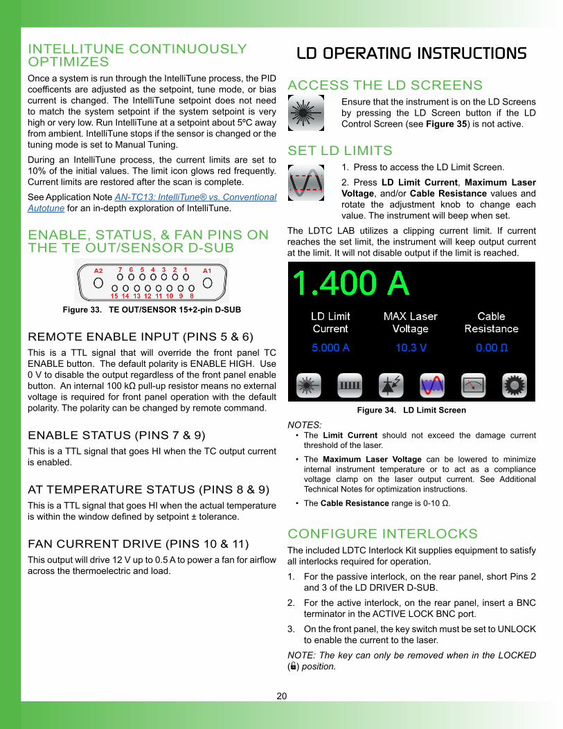
SET LD LIMITS1. Press to access the LD Limit Screen.2. Press LD Limit Current, Maximum Laser Voltage, and/or Cable Resistance values and rotate the adjustment knob to change each value. The instrument will beep when set.
The LDTC LAB utilizes a clipping current limit. If current reaches the set limit, the instrument will keep output current at the limit. It will not disable output if the limit is reached.
Figure 34. LD Limit Screen
NOTES:• The Limit Current should not exceed the damage current
threshold of the laser.• The Maximum Laser Voltage can be lowered to minimize
internal instrument temperature or to act as a compliance voltage clamp on the laser output current. See Additional Technical Notes for optimization instructions.
• The Cable Resistance range is 0-10 Ω.
CONFIGURE INTERLOCKSThe included LDTC Interlock Kit supplies equipment to satisfy all interlocks required for operation.1. For the passive interlock, on the rear panel, short Pins 2
and 3 of the LD DRIVER D-SUB.2. For the active interlock, on the rear panel, insert a BNC
terminator in the ACTIVE LOCK BNC port.3. On the front panel, the key switch must be set to UNLOCK
to enable the current to the laser.NOTE: The key can only be removed when in the LOCKED ( ) position.
21
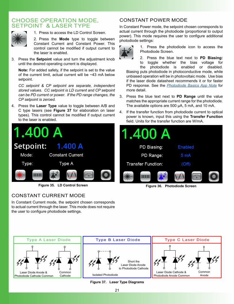
CHOOSE OPERATION MODE, SETPOINT & LASER TYPE
1. Press to access the LD Control Screen.2. Press the Mode type to toggle between Constant Current and Constant Power. This control cannot be modified if output current to the laser is enabled.
3. Press the Setpoint value and turn the adjustment knob until the desired operating current is displayed.Note: For added safety, if the setpoint is set to the value of the current limit, actual current will be ~43 mA below setpoint.CC setpoint & CP setpoint are separate, independent stored values. CC setpoint is LD current and CP setpoint can be PD current or power. If the PD range changes, the CP setpoint is zeroed.
4. Press the Laser Type value to toggle between A/B and C type lasers (see Figure 37 for elaboration on laser types). This control cannot be modified if output current to the laser is enabled.
Figure 35. LD Control Screen
CONSTANT CURRENT MODEIn Constant Current mode, the setpoint chosen corresponds to actual current through the laser. This mode does not require the user to configure photodiode settings.
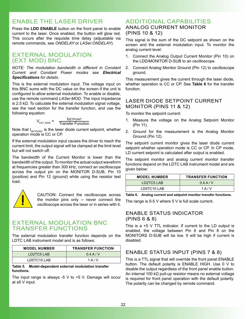
CONSTANT POWER MODEIn Constant Power mode, the setpoint chosen corresponds to actual current through the photodiode (proportional to output power). This mode requires the user to configure additional photodiode settings:
1. Press the photodiode icon to access the Photodiode Screen.2. Press the blue text next to PD Biasing: to toggle whether the bias voltage for the photodiode is enabled or disabled.
Biasing puts photodiode in photoconductive mode, while unbiased operation will be in photovoltaic mode. Use bias if the laser diode datasheet recommends it or for faster PD response. See the Photodiode Basics App Note for more detail.
3. Press the blue text next to PD Range until the value matches the appropriate current range for the photodiode. The available options are 500 μA, 5 mA, and 10 mA.
4. If the transfer function from photodiode current to optical power is known, input this using the Transfer Function field. Units for the transfer function are W/mA.
Figure 36. Photodiode Screen
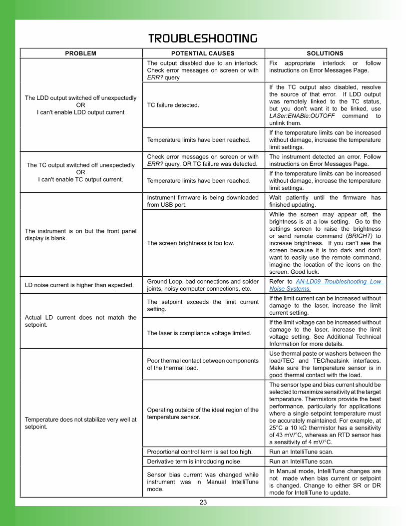
Type A Laser Diode Type B Laser Diode Type C Laser Diode
CommonCathode
Laser Diode Anode & Photodiode Cathode Common Isolated Photodiode
Short theLaser Diode Anode
to Photodiode CathodeCommon
AnodeLaser Diode Cathode &
Photodiode Anode Common
Figure 37. Laser Type Diagrams
22
ENABLE THE LASER DRIVERPress the LDD ENABLE button on the front panel to enable current to the laser. Once enabled, the button will glow red. This occurs after the requisite time delay (adjustable via remote commands, see ONDELAY or LASer:ONDELAY).
EXTERNAL MODULATION (EXT MOD) BNCNOTE: The modulation bandwidth is different in Constant Current and Constant Power modes see Electrical Specifications for details.This is the external modulation input. The voltage input on this BNC sums with the DC value on the screen if the unit is configured to allow external modulation. To enable or disable, use the remote command LASer:MOD. The input impedance is 2.5 kΩ. To calculate the external modulation signal voltage, see the next section for the transfer function, and use the following equation:
VEXT_MOD = ISETPOINT Transfer Function
Note that ISETPOINT is the laser diode current setpoint, whether operation mode is CC or CP.If the external modulation input causes the driver to reach the current limit, the output signal will be clamped at the limit level but will not switch off.The bandwidth of the Current Monitor is lower than the bandwidth of the output. To monitor the actual output waveform at frequencies greater than 300 kHz, connect an oscilloscope across the output pin on the MONITOR D-SUB, Pin 10 (positive) and Pin 12 (ground) while using the resistor test load.
CAUTION: Connect the oscilloscope across the monitor pins only — never connect the oscilloscope across the laser or in series with it.
EXTERNAL MODULATION BNC TRANSFER FUNCTIONSThe external modulation transfer function depends on the LDTC LAB instrument model and is as follows:
MODEL NUMBER TRANSFER FUNCTIONLD2TC5 LAB 0.4 A / VLD5TC10 LAB 1 A / V
Table 5. Model-dependent external modulation transfer functions.
The input range is always -5 V to +5 V. Damage will occur at ±6 V input.
ADDITIONAL CAPABILITIESANALOG CURRENT MONITOR (PINS 10 & 12)This signal is the sum of the DC setpoint as shown on the screen and the external modulation input. To monitor the analog current level:1. Connect the Analog Output Current Monitor (Pin 10) on
the LDD/MONITOR D-SUB to an oscilloscope.2. Connect Analog Monitor Ground (Pin 12) to oscilloscope
ground.This measurement gives the current through the laser diode, whether operation is CC or CP. See Table 6 for the transfer function.
LASER DIODE SETPOINT CURRENT MONITOR (PINS 11 & 12)To monitor the setpoint current:1. Measure the voltage on the Analog Setpoint Monitor
(Pin 11).2. Ground for the measurement is the Analog Monitor
Ground (Pin 12).The setpoint current monitor gives the laser diode current setpoint whether operation mode is CC or CP. In CP mode, LD current setpoint is calculated after output is enabled.The setpoint monitor and analog current monitor transfer functions depend on the LDTC LAB instrument model and are given below:
MODEL NUMBER TRANSFER FUNCTIONLD2TC5 LAB 0.4 A / V
LD5TC10 LAB 1 A / VTable 6. Analog current and setpoint monitor transfer functions.
The range is 0-5 V where 5 V is full scale current.
ENABLE STATUS INDICATOR (PINS 6 & 8)This is a +5 V TTL indicator. If current to the LD output is enabled, the voltage between Pin 6 and Pin 8 on the MONITORS D-SUB will be low. It will be high if current is disabled.
ENABLE STATUS INPUT (PINS 7 & 8)This is a TTL signal that will override the front panel ENABLE button. The default polarity is ENABLE HIGH. Use 0 V to disable the output regardless of the front panel enable button. An internal 100 kΩ pull-up resistor means no external voltage is required for front panel operation with the default polarity. The polarity can be changed by remote command.
23
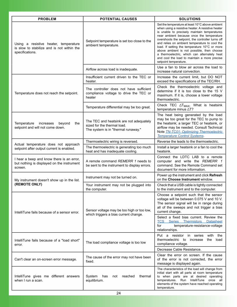
TROUBLESHOOTINGPROBLEM POTENTIAL CAUSES SOLUTIONS
The LDD output switched off unexpectedlyOR
I can't enable LDD output current
The output disabled due to an interlock. Check error messages on screen or with ERR? query
Fix appropriate interlock or follow instructions on Error Messages Page.
TC failure detected.
If the TC output also disabled, resolve the source of that error. If LDD output was remotely linked to the TC status, but you don't want it to be linked, use LASer:ENABle:OUTOFF command to unlink them.
Temperature limits have been reached.If the temperature limits can be increased without damage, increase the temperature limit settings.
The TC output switched off unexpectedlyOR
I can't enable TC output current.
Check error messages on screen or with ERR? query, OR TC failure was detected.
The instrument detected an error. Follow instructions on Error Messages Page.
Temperature limits have been reached.If the temperature limits can be increased without damage, increase the temperature limit settings.
The instrument is on but the front panel display is blank.
Instrument firmware is being downloaded from USB port.
Wait patiently until the firmware has finished updating.
The screen brightness is too low.
While the screen may appear off, the brightness is at a low setting. Go to the settings screen to raise the brightness or send remote command (BRIGHT) to increase brightness. If you can't see the screen because it is too dark and don't want to easily use the remote command, imagine the location of the icons on the screen. Good luck.
LD noise current is higher than expected. Ground Loop, bad connections and solder joints, noisy computer connections, etc.
Refer to AN-LD09 Troubleshooting Low Noise Systems.
Actual LD current does not match the setpoint.
The setpoint exceeds the limit current setting.
If the limit current can be increased without damage to the laser, increase the limit current setting.
The laser is compliance voltage limited.
If the limit voltage can be increased without damage to the laser, increase the limit voltage setting. See Additional Technical Information for more details.
Temperature does not stabilize very well at setpoint.
Poor thermal contact between components of the thermal load.
Use thermal paste or washers between the load/TEC and TEC/heatsink interfaces. Make sure the temperature sensor is in good thermal contact with the load.
Operating outside of the ideal region of the temperature sensor.
The sensor type and bias current should be selected to maximize sensitivity at the target temperature. Thermistors provide the best performance, particularly for applications where a single setpoint temperature must be accurately maintained. For example, at 25°C a 10 kΩ thermistor has a sensitivity of 43 mV/°C, whereas an RTD sensor has a sensitivity of 4 mV/°C.
Proportional control term is set too high. Run an IntelliTune scan.Derivative term is introducing noise. Run an IntelliTune scan.
Sensor bias current was changed while instrument was in Manual IntelliTune mode.
In Manual mode, IntelliTune changes are not made when bias current or setpoint is changed. Change to either SR or DR mode for IntelliTune to update.
24
PROBLEM POTENTIAL CAUSES SOLUTIONS
Using a resistive heater, temperature is slow to stabilize and is not within the specifications.
Setpoint temperature is set too close to the ambient temperature.
Set the temperature at least 10°C above ambient when using a resistive heater. A resistive heater is unable to precisely maintain temperatures near ambient because once the temperature overshoots the setpoint, the controller turns off and relies on ambient temperature to cool the load. If setting the temperature 10°C or more above ambient is not possible, then choose a thermoelectric, which can alternately heat and cool the load to maintain a more precise setpoint temperature.
Airflow across load is inadequate. Use a fan to blow air across the load to increase natural convection.
Temperature does not reach the setpoint.
Insufficient current driven to the TEC or heater.
Increase the current limit, but DO NOT exceed the specifications of the TEC/RH.
The controller does not have sufficient compliance voltage to drive the TEC or heater
Check the thermoelectric voltage and determine if it is too close to the 15 V maximum. If it is, choose a lower voltage thermoelectric.
Temperature differential may be too great. Check TEC TMAX. What is heatsink temperature minus T?
Temperature increases beyond the setpoint and will not come down.
The TEC and heatsink are not adequately sized for the thermal load.The system is in "thermal runaway."
The heat being generated by the load may be too great for the TEC to pump to the heatsink; a larger TEC or heatsink, or airflow may be needed. Consult Technical Note TN-TC01: Optimizing Thermoelectric Temperature Control Systems.
Actual temperature does not approach setpoint after output current is enabled.
Thermoelectric wiring is reversed. Reverse the leads to the thermoelectric.The thermoelectric is generating too much heat and has inadequate cooling.
Install a larger heatsink or a fan to cool the heatsink.
I hear a beep and know there is an error, but nothing is displayed on the instrument screen.
A remote command REMERR 1 needs to be sent to the instrument to display errors.
Connect the LDTC LAB to a remote computer and write the REMERR 1 command. See the Remote Command set document for more information.
My instrument doesn't show up in the list. (REMOTE ONLY)
Instrument may not be turned on. Power up the instrument and click Refresh on the Choose Instrument window.
Your instrument may not be plugged into the computer.
Check that a USB cable is tightly connected to the instrument and to the computer.
IntelliTune fails because of a sensor error. Sensor voltage may be too high or too low, which triggers a bias current change.
Choose a setpoint such that the sensor voltage will be between 0.075 V and 10 V. The sensor signal will be in range during all of the sweeps and not trigger a bias current change.Select a fixed bias current. Review the TCS Series Thermistors Datasheet for temperature-resistance-voltage relationships.
IntelliTune fails because of a "load short" error. The load compliance voltage is too low
Put a resistor in series with the thermoelectric to increase the load compliance voltage.Decrease Cable Resistance.
Can't clear an on-screen error message. The cause of the error may not have been fixed.
Clear the error on screen. If the cause of the error is not corrected, the error message is displayed again.
IntelliTune gives me different answers when I run a scan.
System has not reached thermal equilibrium.
The characteristics of the load will change from initial start with all parts at room temperature to when parts are at desired operating temperatures. Run IntelliTune once all elements of the system have reached operating temperature.
25
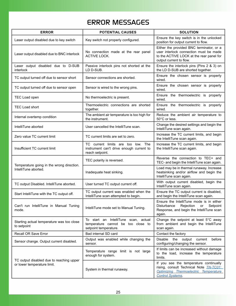
ERROR MESSAGESERROR POTENTIAL CAUSES SOLUTION
Laser output disabled due to key switch Key switch not properly configured. Ensure the key switch is in the unlocked position for output current to flow.
Laser output disabled due to BNC interlock No connection made at the rear panel ACTIVE LOCK.
Either the provided BNC terminator, or a user interlock connection must be made to the ACTIVE LOCK at the rear panel for output current to flow.
Laser output disabled due to D-SUB interlock
Passive interlock pins not shorted at the LD D-SUB.
Ensure the interlock pins (Pins 2 & 3) on the LD D-SUB are shorted together.
TC output turned off due to sensor short Sensor connections are shorted. Ensure the chosen sensor is properly wired.
TC output turned off due to sensor open Sensor is wired to the wrong pins. Ensure the chosen sensor is properly wired.
TEC Load open No thermoelectric is present. Ensure the thermoelectric is properly wired.
TEC Load short Thermoelectric connections are shorted together.
Ensure the thermoelectric is properly wired.
Internal overtemp condition The ambient air temperature is too high for the instrument.
Reduce the ambient air temperature to 50°C or less.
IntelliTune aborted User cancelled the IntelliTune scan. Change the desired settings and begin the IntelliTune scan again.
Zero value TC current limit TC current limits are set to zero. Increase the TC current limits, and begin the IntelliTune scan again.
Insufficient TC current limitTC current limits are too low. The instrument can't drive enough current to reach setpoint.
Increase the TC current limits, and begin the IntelliTune scan again.
Temperature going in the wrong direction. IntelliTune aborted.
TEC polarity is reversed. Reverse the connection to TEC+ and TEC- and begin the IntelliTune scan again.
Inadequate heat sinking.Load may be in thermal runaway. Increase heatsinking and/or airflow and begin the IntelliTune scan again.
TC output Disabled. IntelliTune aborted. User turned TC output current off. With output current disabled, begin the IntelliTune scan again.
Start IntelliTune with the TC output off. TC output current was enabled when the IntelliTune scan attempted to begin.
Ensure the TC output current is disabled, and begin the IntelliTune scan again.
Can't run IntelliTune in Manual Tuning mode. IntelliTune mode set to Manual Tuning.
Ensure the IntelliTune mode is in either Disturbance Rejection or Setpoint Response, and begin the IntelliTune scan again.
Starting actual temperature was too close to setpoint
To start an IntelliTune scan, actual temperature cannot be too close to setpoint temperature.
Change the setpoint at least 5°C away from ambient and begin the IntelliTune scan again.
Recall OR Save Error Bad internal SD card Contact the factory
Sensor change. Output current disabled. Output was enabled while changing the sensor.
Disable the output current before configuring/changing the sensor.
TC output disabled due to reaching upper or lower temperature limit.
Temperature range limit is not large enough for system.
If limits can be increased without damage to the load, increase the temperature limits.
System in thermal runaway.
If you see the temperature continually rising, consult Technical Note TN-TC01: Optimizing Thermoelectric Temperature Control Systems.
26
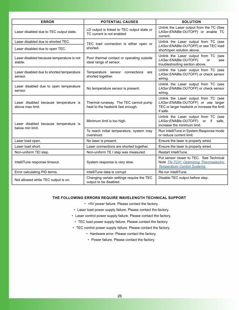
ERROR POTENTIAL CAUSES SOLUTION
Laser disabled due to TEC output state. LD output is linked to TEC output state or TC current is not enabled
Unlink the Laser output from the TC (See LASer:ENABle:OUTOFF) or enable TC current.
Laser disabled due to shorted TEC. TEC load connection is either open or shorted.
Unlink the Laser output from TC (see LASer:ENABle:OUTOFF) or see TEC load short/open solution above.Laser disabled due to open TEC.
Laser disabled because temperature is not stable.
Poor thermal contact or operating outside ideal range of sensor.
Unlink the Laser output from TC (see LASer:ENABle:OUTOFF) or see troubleshooting section above.
Laser disabled due to shorted temperature sensor.
Temperature sensor connections are shorted together.
Unlink the Laser output from TC (see LASer:ENABle:OUTOFF) or check sensor wiring.
Laser disabled due to open temperature sensor. No temperature sensor is present.
Unlink the Laser output from TC (see LASer:ENABle:OUTOFF) or check sensor wiring.
Laser disabled because temperature is above max limit.
Thermal runaway. The TEC cannot pump heat to the heatsink fast enough.
Unlink the Laser output from TC (see LASer:ENABle:OUTOFF) or use larger TEC or larger heatsink or increase the limit if safe.
Laser disabled because temperature is below min limit.
Minimum limit is too high.Unlink the Laser output from TC (see LASer:ENABle:OUTOFF) or if safe, increase the minimum limit.
To reach initial temperature, system may overshoot.
Run IntelliTune in System Response mode or reduce current limit.
Laser load open. No laser is present. Ensure the laser is properly wired.Laser load short. Laser connections are shorted together. Ensure the laser is properly wired.Non-uniform TEI step. Non-uniform TE I step was measured. Restart IntelliTune.
IntelliTune response timeout. System response is very slow.Put sensor closer to TEC. See Technical Note TN-TC01 Optimizing Thermoelectric Temperature Control Systems.
Error calculating PID terms. IntelliTune data is corrupt. Re-run IntelliTune.
Not allowed while TEC output is on. Changing certain settings require the TEC output to be disabled.
Disable TEC output before step.
THE FOLLOWING ERRORS REQUIRE WAVELENGTH TECHNICAL SUPPORT• +5V power failure. Please contact the factory.
• Laser load power supply failure. Please contact the factory.• Laser control power supply failure. Please contact the factory.
• TEC load power supply failure. Please contact the factory.• TEC control power supply failure. Please contact the factory.
• Hardware error. Please contact the factory.• Power failure. Please contact the factory.
27
ADDITIONAL TECHNICAL NOTES
This section includes useful technical information on these topics:
• Using the Max Laser Voltage Limit
• Use Passive and Active ld Interlocks
• Clipping LD Current Limit
• Independent/Linked Operation
USING THE MAX LASER VOLTAGE LIMITThe Maximum Laser Voltage field can be used as a safety feature, and a compliance voltage indicator. If the voltage across the laser attempts to breach the set limit, the instrument will present an error to keep the laser from operating in compliance voltage limited mode (not being able to achieve the full requested output current).
USE PASSIVE AND ACTIVE LD INTERLOCKSThe passive interlock is designed to trigger if Pins 2 and 3 on the LDD D-SUB are not shorted. Use this interlock with doors and enclosures that trigger an open circuit when opened.The active interlock (ACTIVE LOCK BNC) can be used with another active system component to disable/enable the LD current output.
CLIPPING LD CURRENT LIMITThe LDTC LAB utilizes a clipping LD current limit. This means that at a current level very near the current limit, the instrument will clamp the output current at the limit, and continue operating at that level of output current. Output current will not be disabled if the limit is reached.
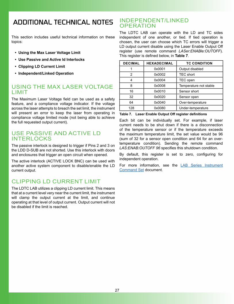
INDEPENDENT/LINKED OPERATIONThe LDTC LAB can operate with the LD and TC sides independent of one another, or tied. If tied operation is chosen, the user can choose which TC errors will trigger a LD output current disable using the Laser Enable Output Off register (use remote command LASer:ENABle:OUTOFF). This register is defined below, in Table 7.
DECIMAL HEXADECIMAL TC CONDITION1 0x0001 Output disabled2 0x0002 TEC short4 0x0004 TEC open8 0x0008 Temperature not stable
16 0x0010 Sensor short32 0x0020 Sensor open64 0x0040 Over-temperature128 0x0080 Under-temperature
Table 7. Laser Enable Output Off register definitions
Each bit can be individually set. For example, if laser current needs to be shut down if there is a disconnection of the temperature sensor or if the temperature exceeds the maximum temperature limit, the set value would be 96 (sum of 32 for a sensor open condition and 64 for an over-temperature condition). Sending the remote command LAS:ENAB:OUTOFF 96 specifies this shutdown condition. By default, this register is set to zero, configuring for independent operation. For more information, see the LAB Series Instrument Command Set document.
28
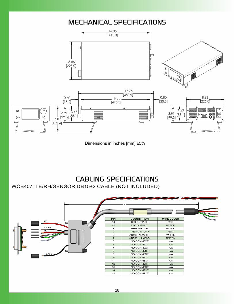
MECHANICAL SPECIFICATIONS
16.35[415.3]
17.75[450.9]
0.60[15.2]
0.80[20.3]
3.47[88.1]
6.0[152.4]
3.91[99.3]
8.86[225.0]
16.35 [415.3]
3.47[88.1]3.91
[99.3]
8.86[225.0]
Dimensions in inches [mm] ±5%
CABLING SPECIFICATIONSWCB407: TE/RH/SENSOR DB15+2 CABLE (NOT INCLUDED)
29
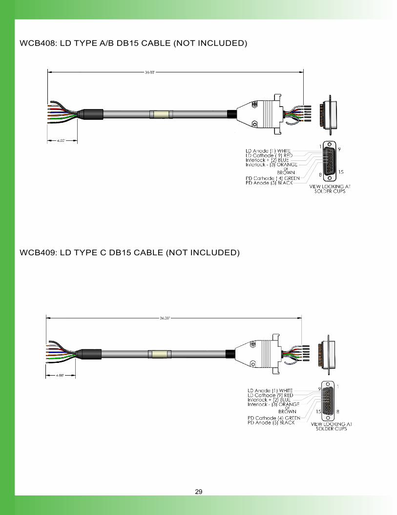
WCB408: LD TYPE A/B DB15 CABLE (NOT INCLUDED)
WCB409: LD TYPE C DB15 CABLE (NOT INCLUDED)
30
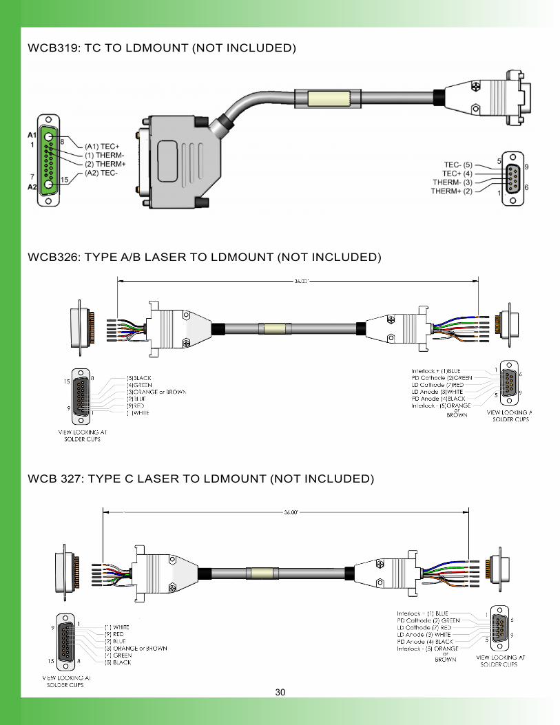
WCB319: TC TO LDMOUNT (NOT INCLUDED)
WCB326: TYPE A/B LASER TO LDMOUNT (NOT INCLUDED)
WCB 327: TYPE C LASER TO LDMOUNT (NOT INCLUDED)
31
WARRANTY & CERTIFICATIONCERTIFICATIONWavelength Electronics, Inc. (Wavelength) certifies that this product met its published specifications at the time of shipment. Wavelength further certifies that its calibration measurements are traceable to the United States National Institute of Standards and Technology, to the extent allowed by that organization’s calibration facilities, and to the calibration facilities of other International Standards Organization members.
WARRANTYThis Wavelength product is warranted against defects in materials and workmanship for a period of one (1) year from date of shipment. During the warranty period, Wavelength will, at its option, either repair or replace products which prove to be defective. Warranty is void if label is removed from back panel.
WARRANTY SERVICEFor warranty service or repair, this product must be returned to the factory. An RMA is required for products returned to Wavelength for warranty service. The Buyer shall prepay shipping charges to Wavelength and Wavelength shall pay shipping charges to return the product to the Buyer upon determination of defective materials or workmanship. However, the Buyer shall pay all shipping charges, duties, and taxes for products returned to Wavelength from another country.
LIMITATIONS OF WARRANTYThe warranty shall not apply to defects resulting from improper use or misuse of the product or operation outside published specifications. Warranty for the TC LAB instrument is invalid if the instrument cover has been removed for any reason. No other warranty is expressed or implied. Wavelength specifically disclaims the implied warranties of merchantability and fitness for a particular purpose.
EXCLUSIVE REMEDIESThe remedies provided herein are the Buyer’s sole and exclusive remedies. Wavelength shall not be liable for any direct, indirect, special, incidental, or consequential damages, whether based on contract, tort, or any other legal theory.
REVERSE ENGINEERING PROHIBITEDBuyer, End-User, or Third-Party Reseller are expressly prohibited from reverse engineering, decompiling, or disassembling this product.
NOTICEThe information contained in this document is subject to change without notice. Wavelength will not be liable for errors contained herein or for incidental or consequential damages in connection with the furnishing, performance, or use of this material. No part of this document may be translated to another language without the prior written consent of Wavelength.
SAFETYThere are no user-serviceable parts inside this product. Return the product to Wavelength Electronics for service and repair to ensure that safety features are maintained.
LIFE SUPPORT POLICYThis important safety information applies to all Wavelength electrical and electronic products and accessories:
As a general policy, Wavelength Electronics, Inc. does not recommend the use of any of its products in life support applications where the failure or malfunction of the Wavelength product can be reasonably expected to cause failure of the life support device or to significantly affect its safety or effectiveness. Wavelength will not knowingly sell its products for use in such applications unless it receives written assurances satisfactory to Wavelength that the risks of injury or damage have been minimized, the customer assumes all such risks, and there is no product liability for Wavelength. Examples of devices considered to be life support devices are:
neonatal oxygen analyzers, nerve stimulators (for any use), auto-transfusion devices, blood pumps, defibrillators, arrhythmia detectors and alarms, pacemakers, hemodialysis systems, peritoneal dialysis systems, ventilators of all types, and infusion pumps as well as other devices designated as “critical” by the FDA.
The above are representative examples only and are not intended to be conclusive or exclusive of any other life support device.
TECHNICAL SUPPORT & CONTACT INFORMATION
WAVELEnGTH E L E C T R O N I C S
51 Evergreen DriveBozeman, Montana 59715
406-587-4910 (tel)406-587-4911 (fax)
Sales & Tech [email protected]
REVISION HISTORYDocument Number: LD2TC5-LA400
REVISION DATE NOTESA September 2019 Initial Release