latcha/me486/ME_486_Equations.docx · Web viewLoading factor: k c =1 for bending, 0.85 for axial...
31
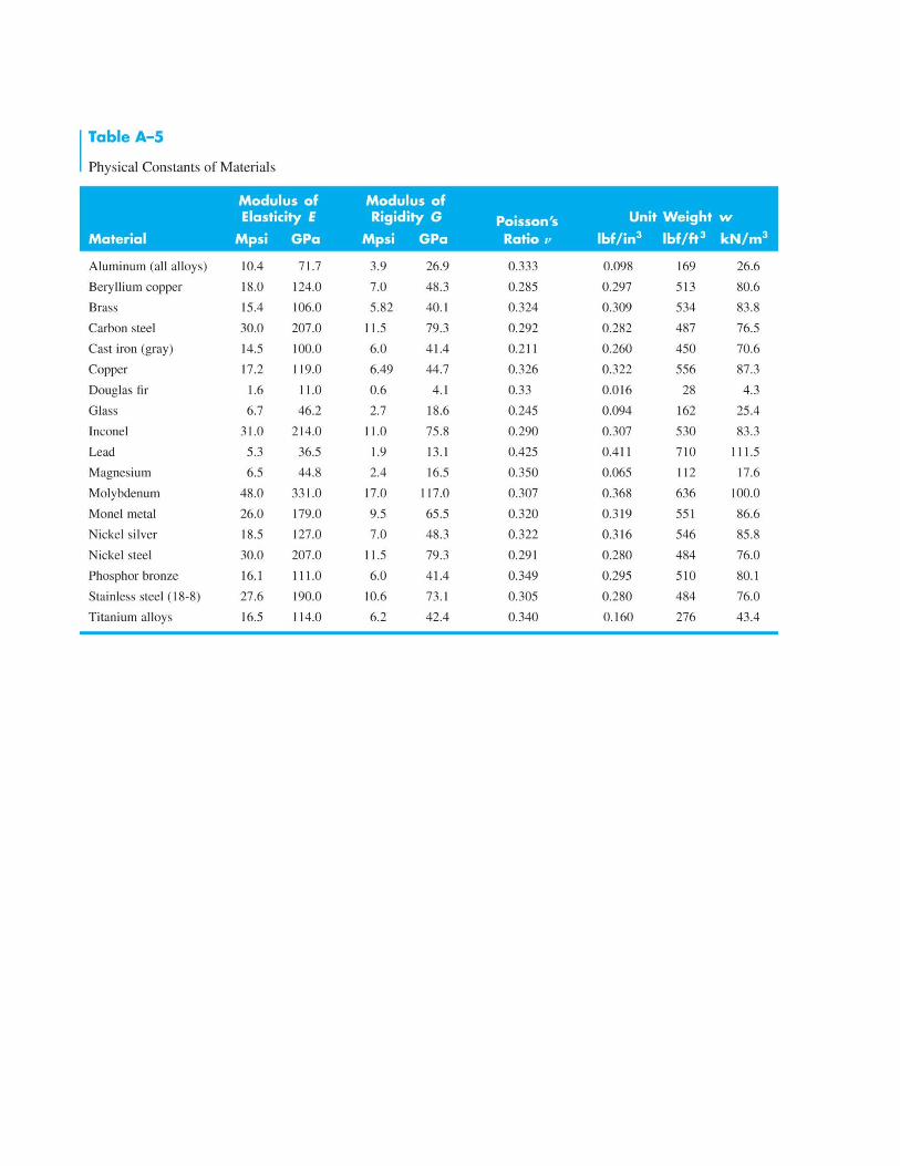
ME 486 - Design of Mechanical Systems Quiz and Exam Resource Geometry Rectangle: A =bh I= 1 12 bh 3 Circle: A = π 4 d 2 I= π 64 d 4 J= π 32 d 4 Stress Transformations τ max,xy = √ ( σ x −σ y 2 ) 2 +τ xy 2 ; σ Pxy = σ x + σ y 2 ±τ max ,xy ; σ 1 ≥σ 2 ≥σ 3 ; τ max = σ 1 −σ 3 2 Stresses and deformations Tension, Compression: σ =P/ A ; δ=PL / AE ; U= P 2 L 2 AE Direct Shear: τ=F / A Torsion: τ=Tr / J ; τ max = Tc J ; θ=TL / GJ ; U= T 2 L 2 GJ Pure bending: σ = −My I ; σ max = Mc I ; M EI = d 2 y dx 2 U= ∫ M 2 2 EI dx ; δ= 1 EI ∫ M ∂M ∂P dx Singularity functions: Concentrated moment at x=a: M ( x) =−M 0 < x−a ¿ 0 Concentrated force at x=a: M ( x) =P< x−a ¿ 1 Uniformly distributed load starting at x=a: M ( x) = 1 2 w <x−a ¿ 2 Ramp starting at x=a: M ( x) = 1 6 k <x−a ¿ 3 ¿ x−a ¿ n =¿ if x ≥ a, = if x ≤ a ∫ ¿ x−a ¿ n dx = 1 n +1 <x−a ¿ n+1 if n > 0 ∫ ¿ x−a ¿ n dx =¿ x−a ¿ n +1 if n ≤ 0
Transcript of latcha/me486/ME_486_Equations.docx · Web viewLoading factor: k c =1 for bending, 0.85 for axial...
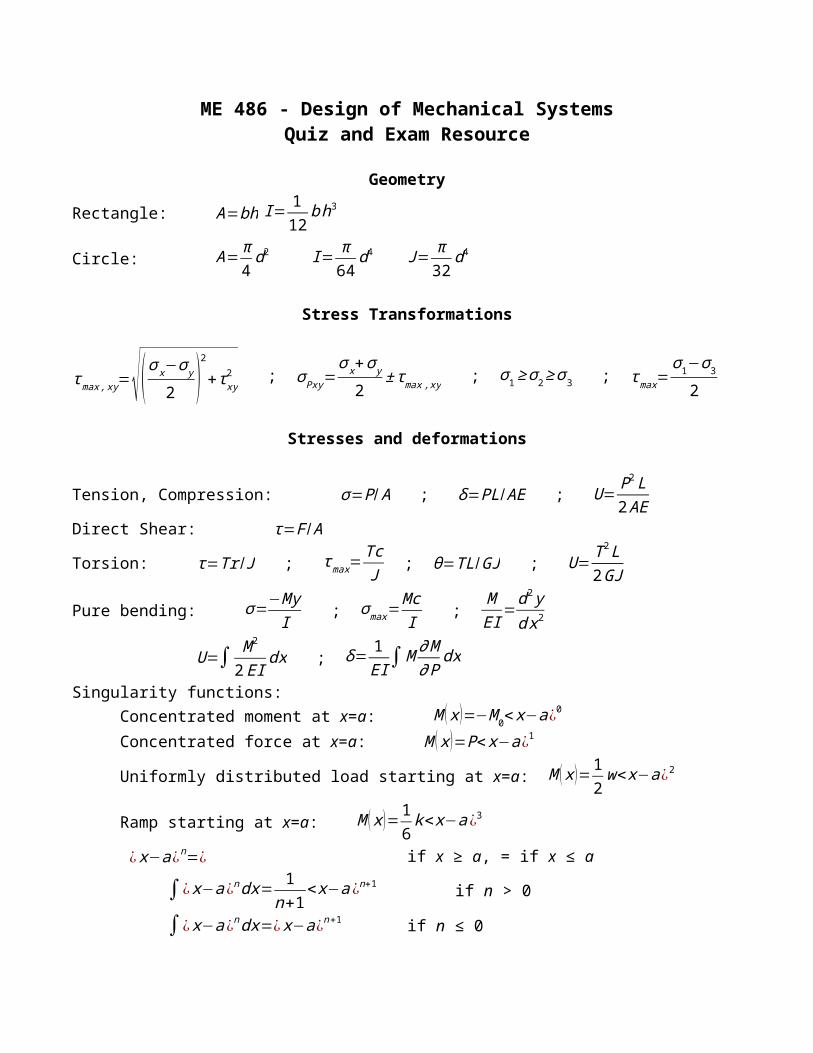
ME 486 - Design of Mechanical SystemsQuiz and Exam Resource
Geometry
Rectangle: A=bh I= 112
bh3
Circle: A=π4d2 I= π
64d4 J= π
32d4
Stress Transformations
τ max, xy=√( σx−σ y
2 )2
+ τ xy2 ; σ Pxy=
σ x+σ y
2± τmax, xy ; σ 1≥σ2≥σ3 ; τ max=
σ1−σ32
Stresses and deformations
Tension, Compression: σ=P / A ; δ=PL /AE ; U= P2 L2 AE
Direct Shear: τ=F /A
Torsion: τ=Tr /J ; τ max=TcJ ; θ=TL /GJ ; U= T2 L
2GJ
Pure bending: σ=−MyI ; σ max=
McI ;
MEI
=d2 yd x2
U=∫ M 2
2 EIdx ; δ=
1EI∫M ∂M
∂ Pdx
Singularity functions: Concentrated moment at x=a: M (x )=−M 0< x−a¿0
Concentrated force at x=a: M (x )=P< x−a¿1
Uniformly distributed load starting at x=a: M (x )=12w<x−a¿2
Ramp starting at x=a: M (x )=16k<x−a ¿3
¿ x−a¿n=¿ if x ≥ a, = if x ≤ a
∫¿ x−a¿ndx= 1n+1
<x−a¿n+1 if n > 0
∫¿ x−a¿ndx=¿ x−a¿n+1 if n ≤ 0
Shear stress due to bending: τ=VQ¿
τ max=4 V3 A (circular section) ; τ max=
3V2 A (rectangular section) ; τ max=
VAweb
(structural shape)
Castigliano's Theorem: δ=∂U total
∂ F i
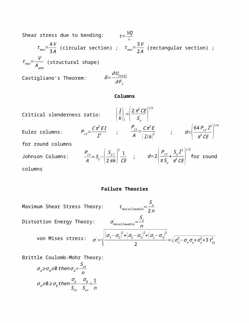
Columns
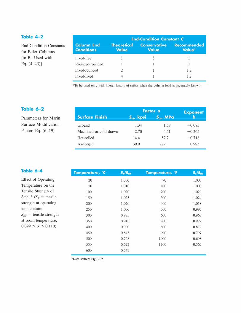
Critical slenderness ratio: ( lk )1=(2π2CES y )
1 /2
Euler columns: Pcr=C π2EI
l2 ;
Pcr
A=C π2E
(l /k )2 ; d=( 64 Pcr l
2
π 3CE )1 /4
for round columns
Johnson Columns: P cr
A=S y−( S y l
2πk )2 1CE
; d=2( Pcr
π S y+
S y l2
π2CE )1/2
for round columns
Failure Theories
Maximum Shear Stress Theory: τ maxall owable=Sy
2n
Distortion Energy Theory: σ maxallowable' =
S y
n
von Mises stress: σ '=√ (σ 1−σ2 )2+(σ2−σ3 )2+ (σ1−σ3 )2
2=√σ x
2−σ x σ y+σ y2+3 τxy
2
Brittle Coulomb-Mohr Theory:
σ A≥σB≥0 thenσ A=Sut
n
σ A≥0≥σ B thenσ A
Sut−
σB
Suc=1n
0≥σ A≥σ B thenσ B=−Sucn
Endurance limit: Se' =0.5 Sut if Sut≤200 kpsi (1400MPa ) ,100kpsi (1400MPa ) if not
Fatigue strength: Sf=a Nb ;a=(0.9Sut )
2
Se;b=−1
3 log (0.9 SutSe )Endurance limit: Se=Se
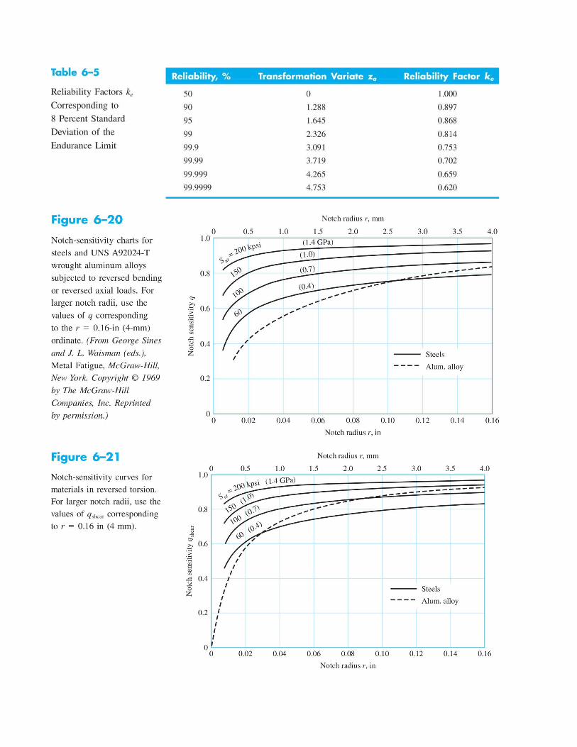
' ka kb k ckd ke
Surface finish factor: k a=a Sutb
Size factor: k b=0.879d−0.107 if 0.11≤d≤2∈;kb=0.910d
−0.157 if 2<d≤10∈¿k b=1.24d
−0.107 if 2.79≤d≤51mm; kb=1.51d−0.157 if 51<d≤254mm
de=0.370d for nonrotating round ,de=0.808√hb for nonrotating rectanglekb = 1 for axial loads
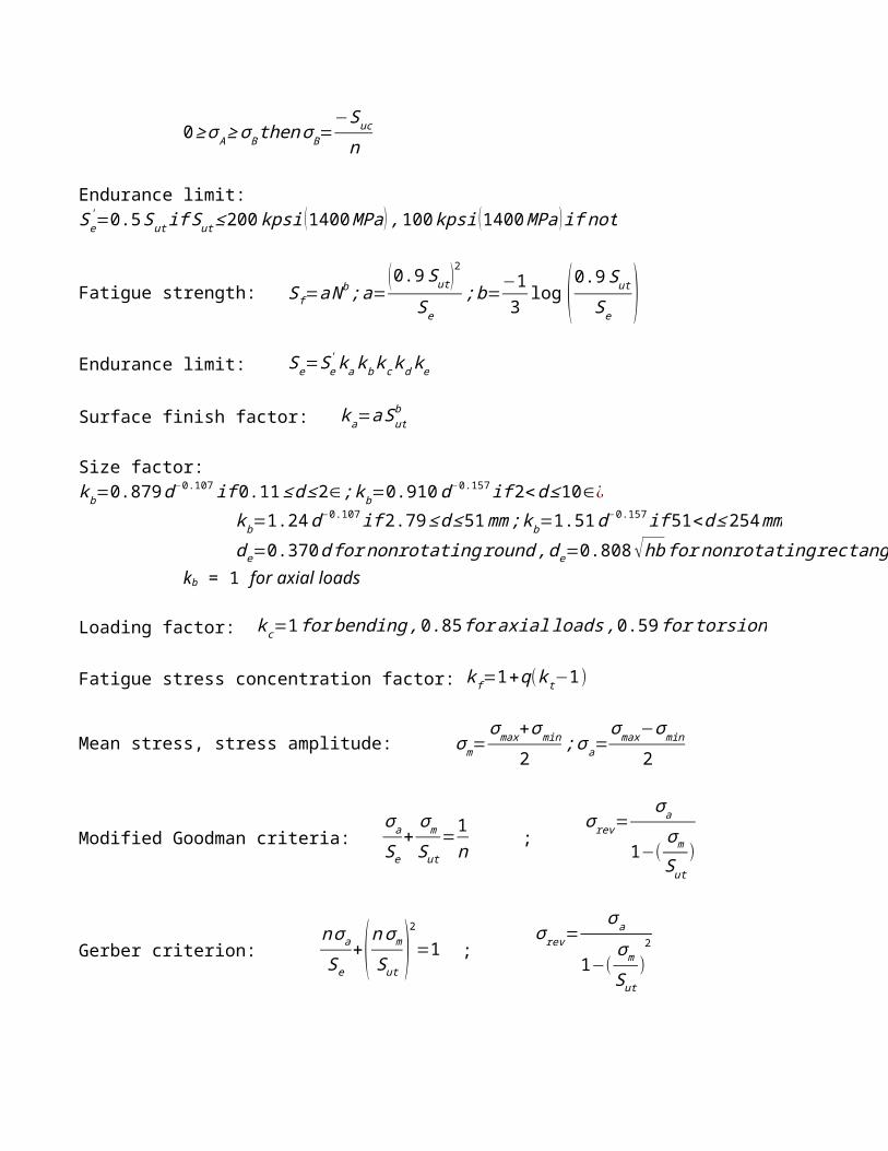
Loading factor: k c=1 for bending ,0.85 for axial loads ,0.59 for torsion
Fatigue stress concentration factor: k f=1+q(k t−1)
Mean stress, stress amplitude: σ m=σmax+σmin
2;σ a=
σmax−σ min
2
Modified Goodman criteria: σa
Se+σm
Sut=1n ;
σ rev=σ a
1−(σm
Sut)
Gerber criterion: nσa
Se+( nσ m
Sut)2
=1 ; σ rev=
σa
1−(σm
Sut)2
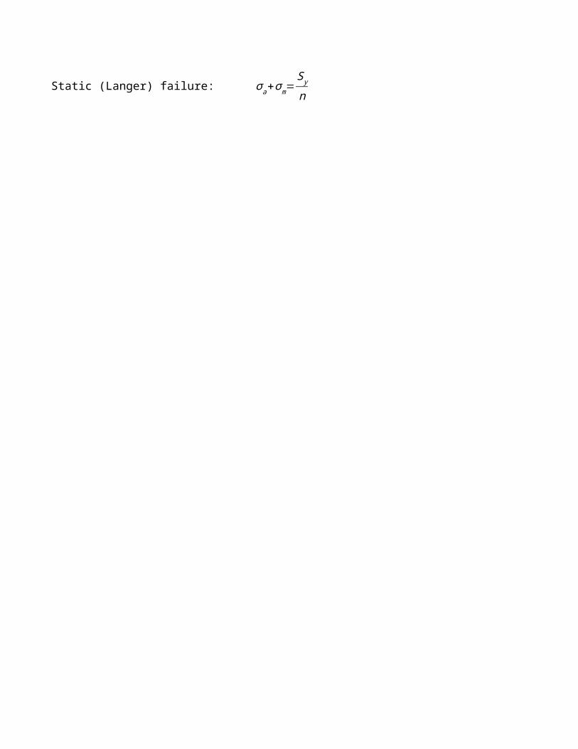
Static (Langer) failure: σ a+σm=S y
n
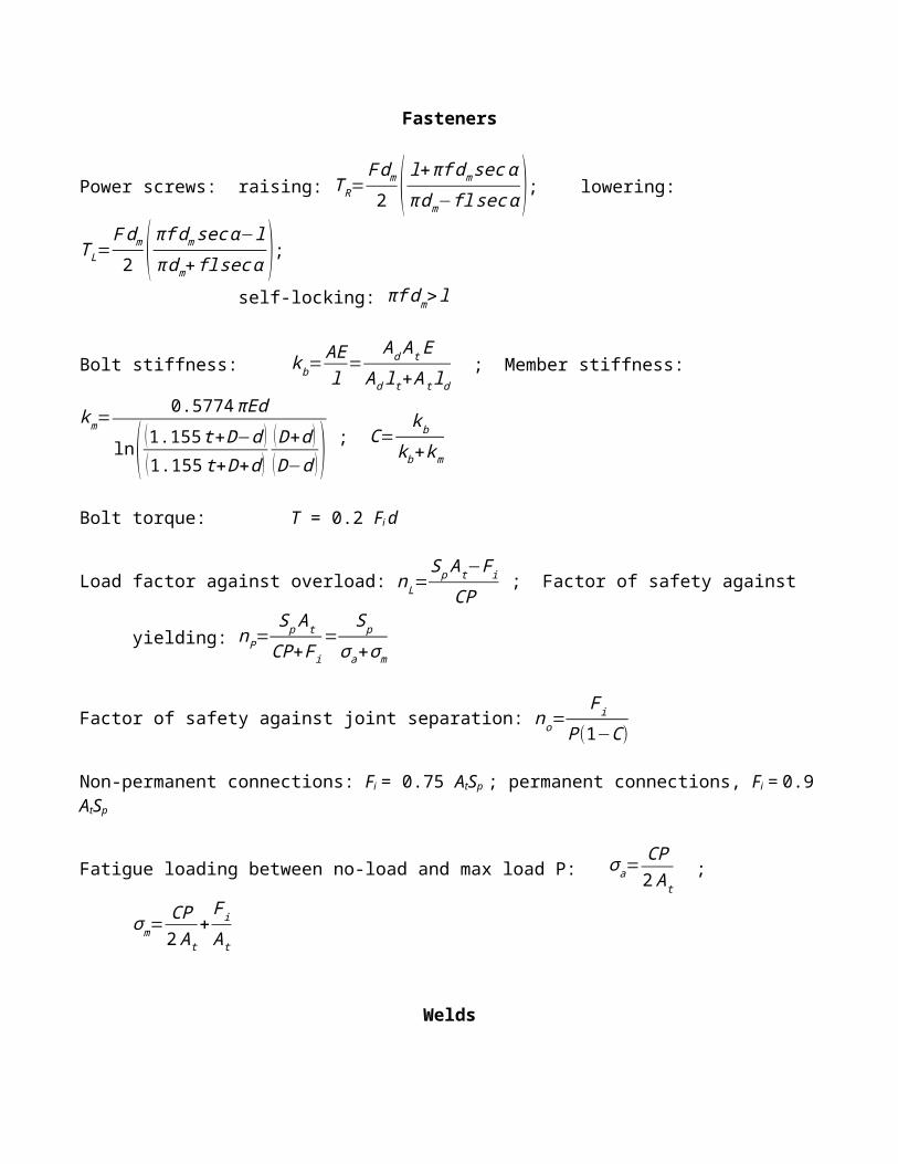
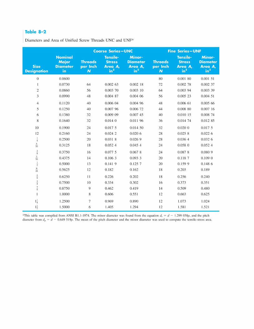
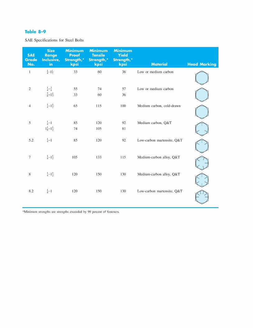
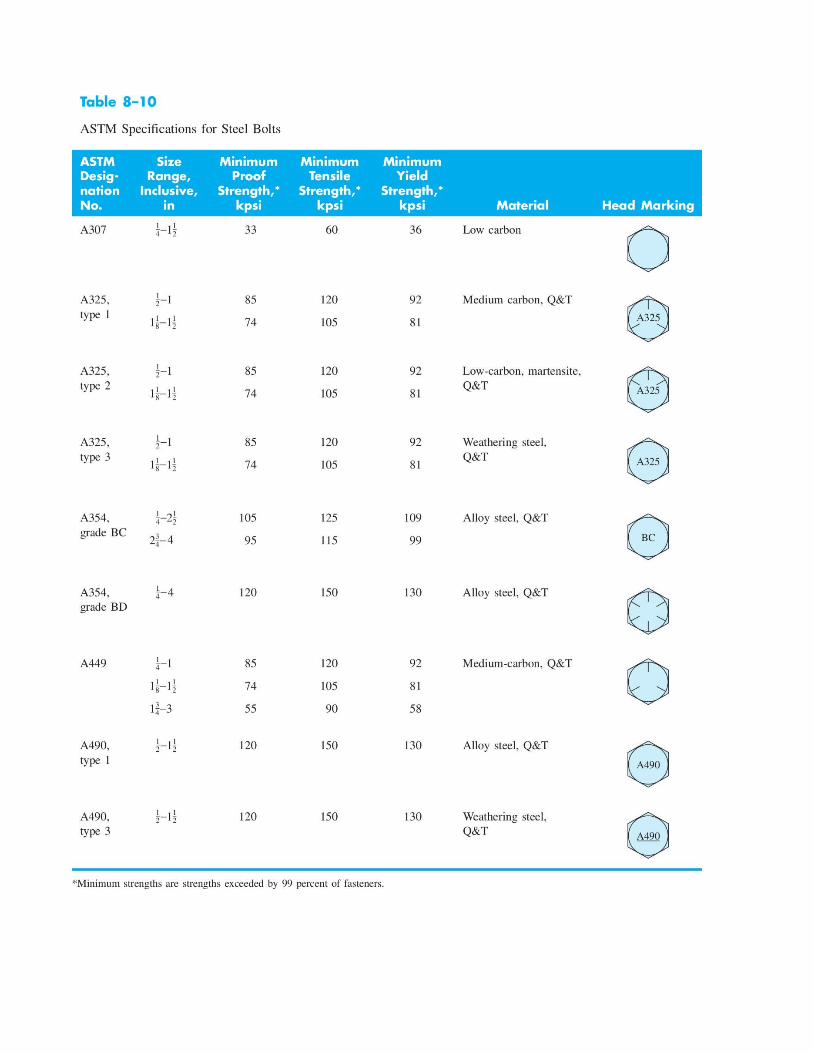
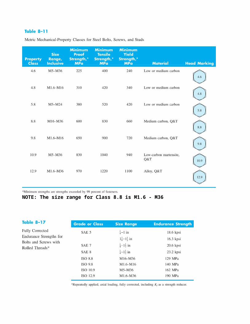
Fasteners
Power screws: raising: T R=F dm
2 ( l+πf dm sec απ dm−fl sec α ); lowering: T L=
F dm
2 ( πf dm sec α−lπ dm+fl sec α );
self-locking: πf dm> l
Bolt stiffness: k b=AEl
=Ad A t E
Ad lt+A t ld ; Member stiffness:
km=0.5774 πEd
ln( (1.155 t+D−d )(1.155 t+D+d )
(D+d )(D−d ) ) ;
C=kb
kb+km
Bolt torque: T = 0.2 Fi d
Load factor against overload: nL=Sp At−F i
CP ; Factor of safety against yielding: nP=
S p A t
CP+Fi=
Sp
σa+σm
Factor of safety against joint separation: no=F i
P (1−C)
Non-permanent connections: Fi = 0.75 AtSp ; permanent connections, Fi = 0.9 AtSp
Fatigue loading between no-load and max load P: σ a=CP2 A t
; σ m=CP2 A t
+Fi
At
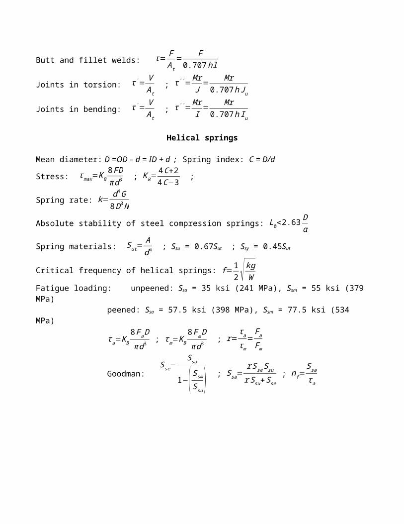
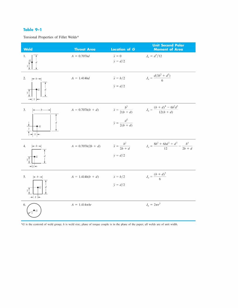
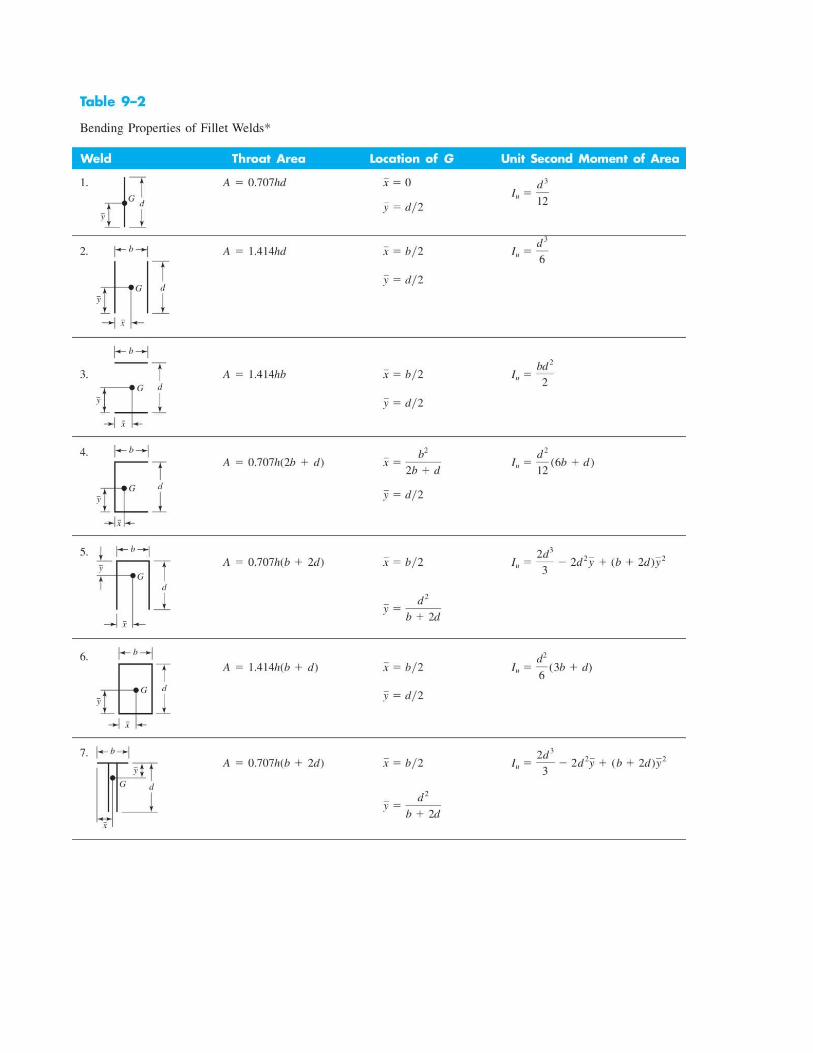
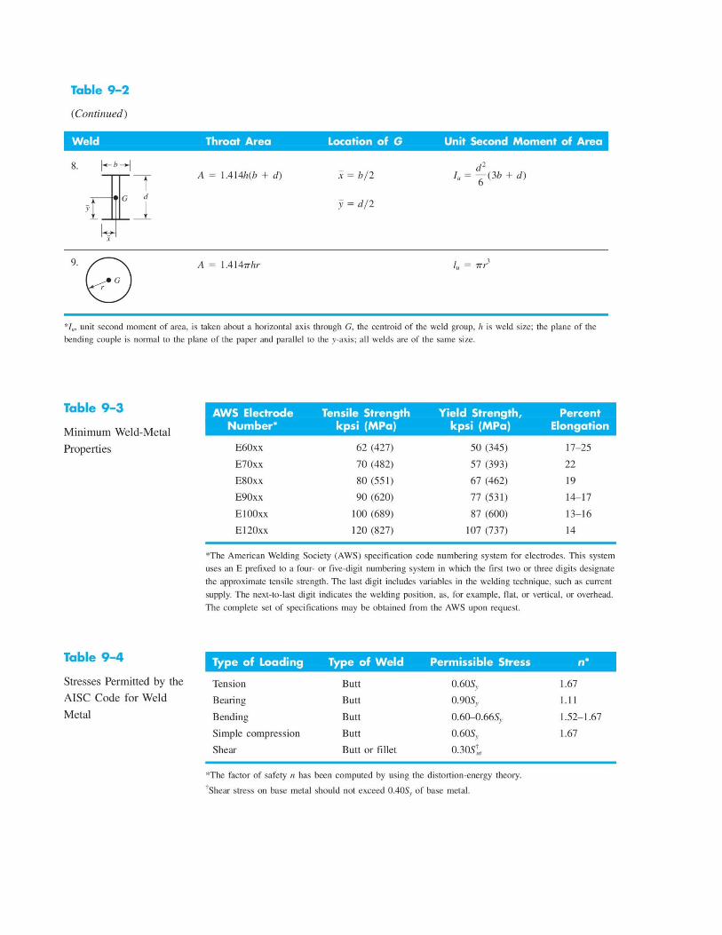
Welds
Butt and fillet welds: τ= FA t
= F0.707hl
Joints in torsion: τ '= VAt
; τ' '=Mr
J= Mr0.707hJ u
Joints in bending: τ '= VAt
; τ' '=Mr
I= Mr0.707h Iu
Helical springs
Mean diameter: D =OD – d = ID + d ; Spring index: C = D/d
Stress: τ max=K B8 FDπ d3
; K B=4C+24C−3 ;
Spring rate: k= d4G8D3 N
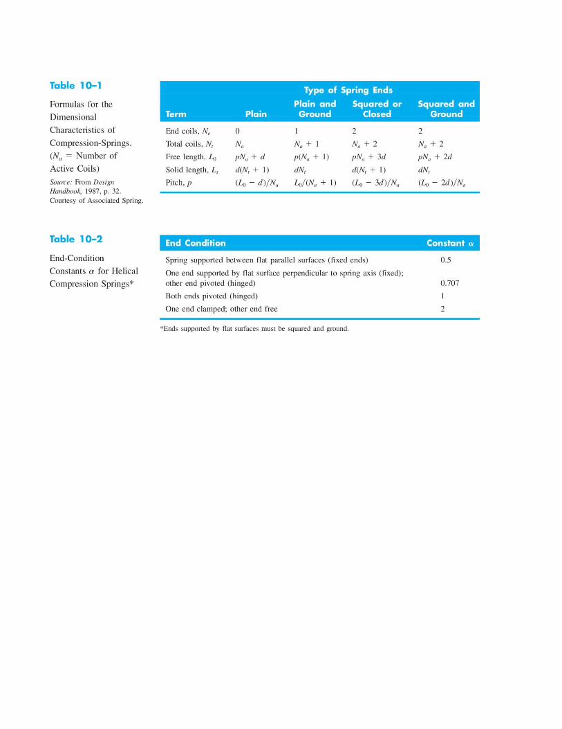
Absolute stability of steel compression springs: L0<2.63Dα
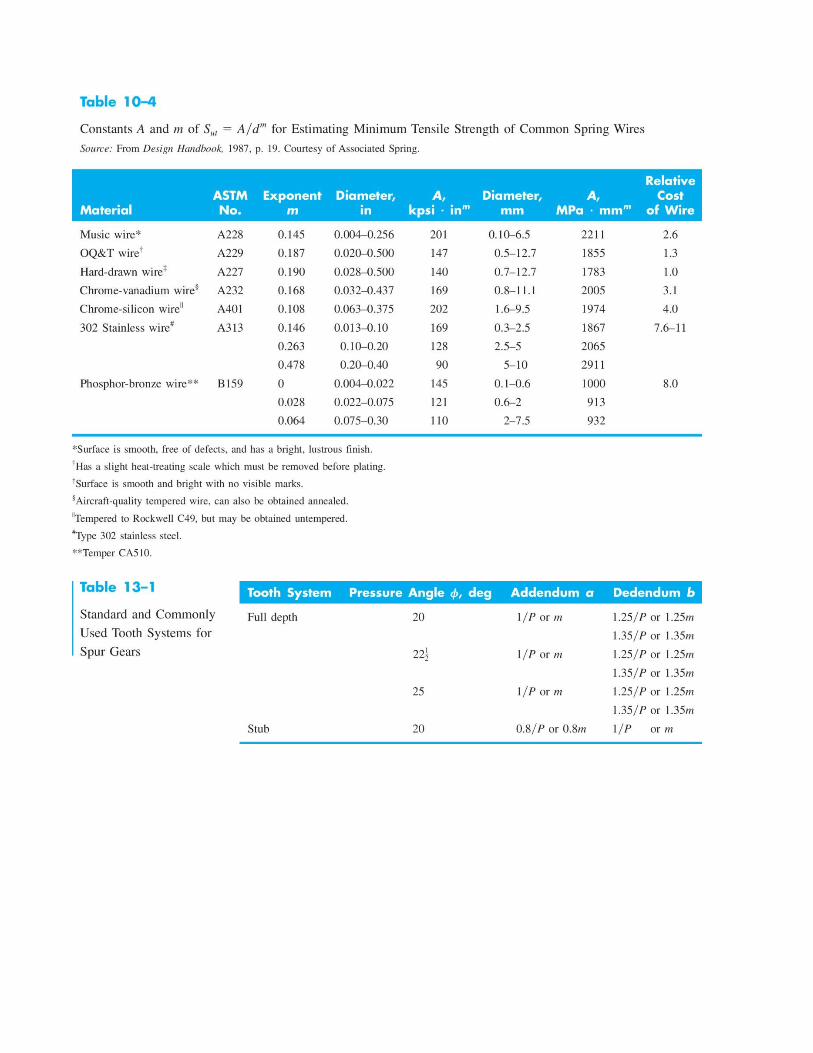
Spring materials: Sut=Adm ; Ssu = 0.67Sut ; Ssy = 0.45Sut
Critical frequency of helical springs: f= 12 √ kg
W
Fatigue loading: unpeened: Ssa = 35 ksi (241 MPa), Ssm = 55 ksi (379 MPa)peened: Ssa = 57.5 ksi (398 MPa), Ssm = 77.5 ksi (534 MPa)
τ a=KB
8 FaDπ d3
; τ m=KB
8 FmDπ d3
; r=τaτm
=Fa
Fm
Goodman: Sse=
Ssa
1−( Ssm
Ssu ) ; Ssa=r Sse Ssur Ssu+Sse
; n f=Ssa
τa
Gearing
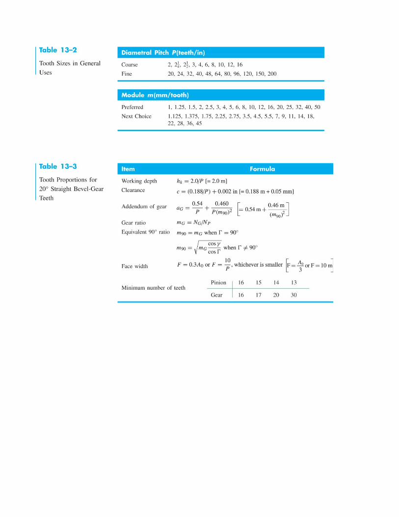
Circular pitch = pDiametral pitch = P = N/d ; module = d/NpP = π
Train value: nlast=enfirst ; e=(−1 )¿ gear interfaces Product of driving toothnumbersProduct of driventoothnumbers
Planetary systems: e=nL−na
nF−na
W t=33000HV ; Wt (pounds), H (hp), V=πdn /12 = pitch-line velocity in ft/min, d (in), n(rpm)
W t=60000H
πdn ; Wt (kN), H (kW), d (mm), n (rpm)
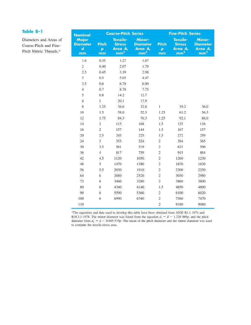
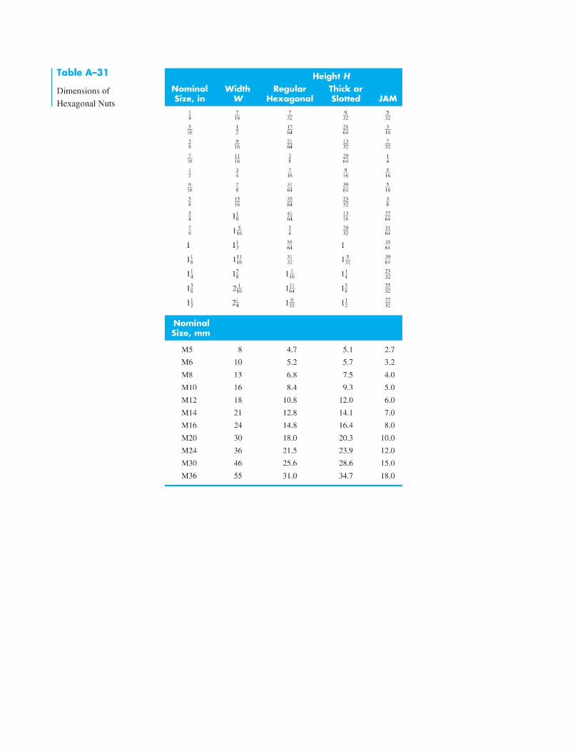
NOTE: The size range for Class 8.8 is M1.6 - M36


![BIOELECTRO- MAGNETISM - Bioelectromagnetism · Generation of bioelectric signal V. m [mV] 200. 400. 800. 1000-100-50. 0. 50. Time [ms] K + Na + K + K + K + K + K + K + K + K + K +](https://static.fdocument.org/doc/165x107/5ad27ef17f8b9a72118d34d0/bioelectro-magnetism-bi-of-bioelectric-signal-v-m-mv-200-400-800-1000-100-50.jpg)