kd - University of San Diego Home Pageshome.sandiego.edu/~ekim/e171f00/lectures/arrays.pdf · EEE...
2
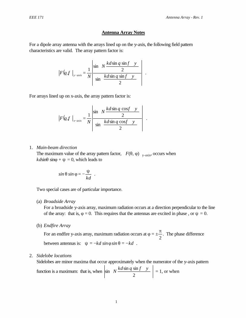
EEE 171 Antenna Array - Rev. 1 1 Antenna Array Notes For a dipole array antenna with the arrays lined up on the y-axis, the following field pattern characteristics are valid. The array pattern factor is: ( = - 2 sin sin sin 2 sin sin sin 1 , y f q y f q f q kd kd N N F axis y . For arrays lined up on x-axis, the array pattern factor is: ( = - 2 cos sin sin 2 cos sin sin 1 , y f q y f q f q kd kd N N F axis x . 1. Main-beam direction The maximum value of the array pattern factor, F(θ, φ) y-axis , occurs when kdsin θ sin φ + ψ = 0, which leads to sin sin θ φ ψ =- kd . Two special cases are of particular importance. (a) Broadside Array For a broadside y-axis array, maximum radiation occurs at a direction perpendicular to the line of the array: that is, φ = 0. This requires that the antennas are excited in phase , or ψ = 0. (b) Endfire Array For an endfire y-axis array, maximum radiation occurs at φ = ± π 2 . The phase difference between antennas is: ψ φ θ = - = - kd kd sin sin . 2. Sidelobe locations Sidelobes are minor maxima that occur approximately when the numerator of the y-axis pattern function is a maximum: that is, when 2 sin sin sin y f q kd N = 1, or when
-
Upload
nguyenthien -
Category
Documents
-
view
216 -
download
3
Transcript of kd - University of San Diego Home Pageshome.sandiego.edu/~ekim/e171f00/lectures/arrays.pdf · EEE...
EEE 171 Antenna Array - Rev. 1
1
Antenna Array Notes For a dipole array antenna with the arrays lined up on the y-axis, the following field pattern characteristics are valid. The array pattern factor is:
( )
+
+
=−
2sinsin
sin
2sinsin
sin1
,ψφθ
ψφθ
φθkd
kdN
NF
axisy .
For arrays lined up on x-axis, the array pattern factor is:
( )
+
+
=−
2cossin
sin
2cossin
sin1
,ψφθ
ψφθ
φθkd
kdN
NF
axisx .
1. Main-beam direction The maximum value of the array pattern factor, F(θ, φ)y-axis, occurs when kdsinθ sinφ + ψ = 0, which leads to
sin sinθ φψ
= −kd
.
Two special cases are of particular importance.
(a) Broadside Array For a broadside y-axis array, maximum radiation occurs at a direction perpendicular to the line
of the array: that is, φ = 0. This requires that the antennas are excited in phase , or ψ = 0. (b) Endfire Array
For an endfire y-axis array, maximum radiation occurs at φ = ±π2
. The phase difference
between antennas is: ψ φ θ= − = −kd kdsin sin .
2. Sidelobe locations Sidelobes are minor maxima that occur approximately when the numerator of the y-axis pattern
function is a maximum: that is, when
+
2sinsin
sinψφθkd
N = 1, or when

EEE 171 Antenna Array - Rev. 1
2
( )2
122sinsin πψφθ
+±=+
mkd
N , m = 1, 2, 3, ...
The first sidelobes occur when
Nkd sin sinθ φ ψ π+
= ±2
32
(for m = 1).
Note that Nkd sin sinθ φ ψ π+
= ±2 2
(for m = 0) does not represent locations of sidelobes
because they are still within the main-beam region. 3. First sidelobe level An important characteristic of the radiation pattern of a y-axis array antenna is the level of the first
sidelobe compared to that of the main beam, since the former is usually the highest of all sidelobes. All sidelobes should be kept as low as possible in order that most of the radiated power be concentrated in the main-beam direction and not be diverted to sidelobe regions. The amplitude of the first sidelobe is,
NN
23
sin
11π
.
![Parallel-Plate Slot Array Antenna for MicroXSARMission · Rectangular waveguide feeder to each panel [top view] [bottom view] Choke Flange x z y 70 cm 70 cm LHCP port x z y Parallel-Plate](https://static.fdocument.org/doc/165x107/5e109940975bb7371154d141/parallel-plate-slot-array-antenna-for-microxsarmission-rectangular-waveguide-feeder.jpg)