Iron Iron-Carbide Diagram(MSM)
30
Material Science and Metallurgy Topic:~Iron Iron-Carbide Diagram (Basic Definitions & States) Mechanical Department
-
Upload
gandhinagar-institute-of-technology -
Category
Engineering
-
view
81 -
download
6
Transcript of Iron Iron-Carbide Diagram(MSM)
Material Science and Metallurgy
Topic:~Iron Iron-Carbide Diagram (Basic Definitions & States)
Mechanical Department

Prepared by
• Kushal Panchal
Definition of structures
•Various phases that appear on the Iron-Carbon
equilibrium phase diagram are as under:
•Austenite
•Ferrite
•Pearlite
•Cementite
•Martensite
•Ledeburite
Definition of structures
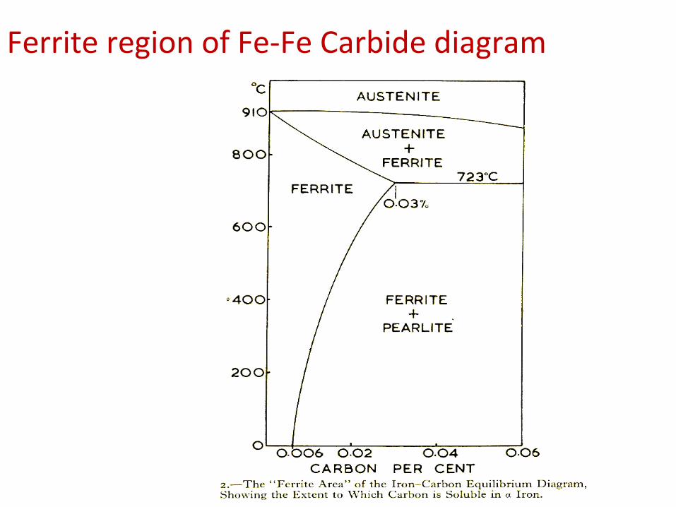
• Ferrite is known as α solid solution.
• It is an interstitial solid solution of a small amount of carbon dissolved in α (BCC) iron.
• stable form of iron below 912 deg.C
• The maximum solubility is 0.025 % C at 723 deg.C and it dissolves only 0.008 % C at room temperature.
• It is the softest structure that appears on the diagram.
Definition of structures
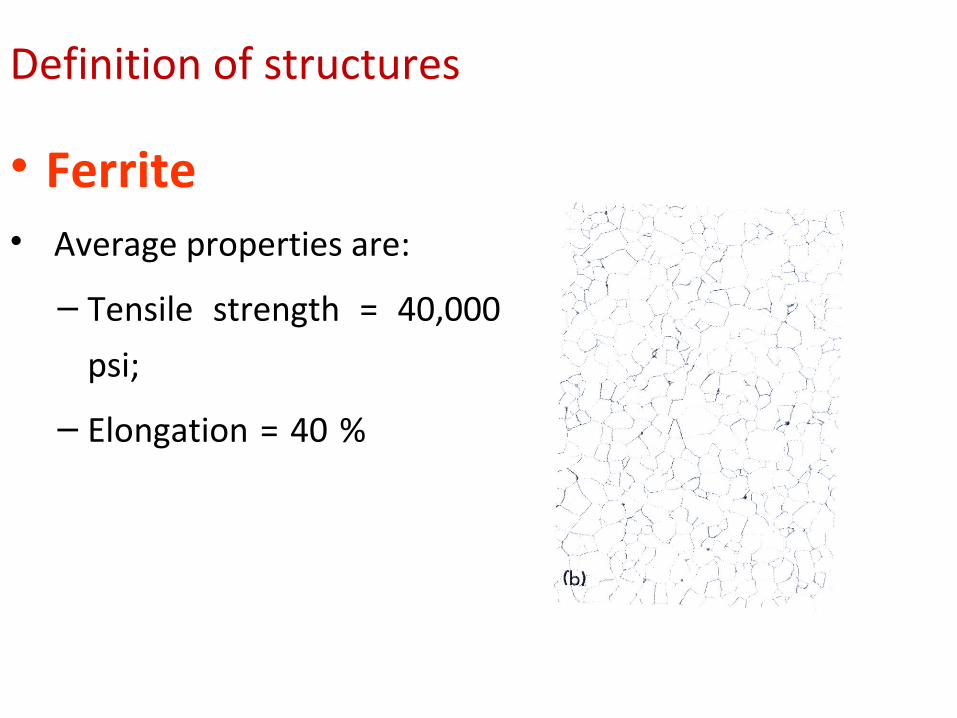
• Ferrite • Average properties are:
– Tensile strength = 40,000
psi;
– Elongation = 40 %
Definition of structures
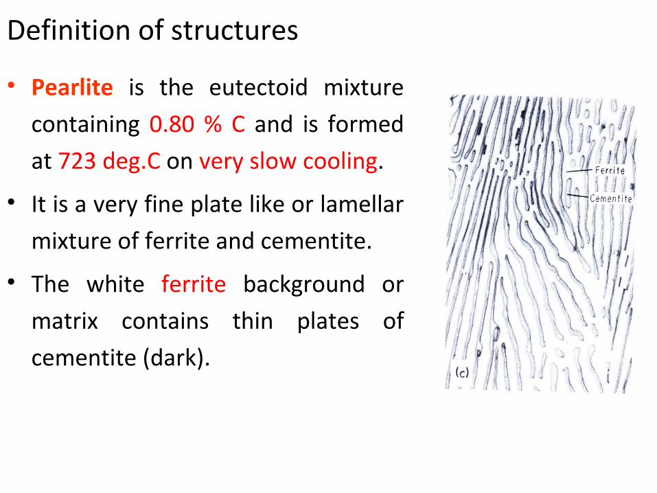
• Pearlite is the eutectoid mixture
containing 0.80 % C and is formed
at 723 deg.C on very slow cooling.
• It is a very fine plate like or lamellar
mixture of ferrite and cementite.
• The white ferrite background or
matrix contains thin plates of
cementite (dark).
Definition of structures• Austenite is an interstitial solid solution of Carbon
dissolved in γ (F.C.C.) iron.
• Maximum solubility is 2.0 % C at 1130 deg.C.
• High formability, most of heat treatments begin with this
single phase.
• It is normally not stable at room temperature. But, under
certain conditions it is possible to obtain austenite at room
temperature.
Definition of structures
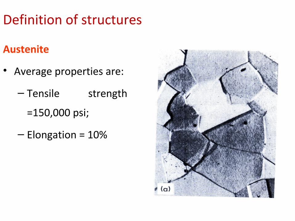
Austenite
• Average properties are:
– Tensile strength
=150,000 psi;
– Elongation = 10%
Definition of structures
• Cementite or iron carbide, is very hard, brittle
intermetallic compound of iron & carbon, as Fe3C, contains
6.67 % C.• It is the hardest structure that appears on the diagram,
exact melting point unknown.• It is has – low tensile strength (approx. 5,000 psi), but – high compressive strength.
Definition of structures
• Ledeburite is the eutectic mixture of austenite and
cementite.
• It contains 4.3 percent C and is formed at 1130°C.
Definition of structures
• Martensite - a super-saturated solid solution of carbon in ferrite.
• It is formed when steel is cooled so rapidly that the change from austenite to pearlite is suppressed.
Iron Iron-Carbide Diagram
The Iron-Iron Carbide Diagram
• A map of the temperature at which different phase
changes occur on very slow heating and cooling in relation
to Carbon, is called Iron- Carbon Diagram.• Iron- Carbon diagram shows – The type of alloys formed under very slow cooling, – Proper heat-treatment temperature and– How the properties of steels and cast irons can be
radically changed by heat-treatment.
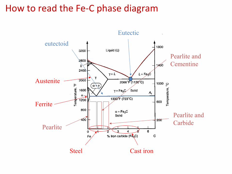
How to read the Fe-C phase diagram
Ferrite
Austenite
Steel Cast iron
Pearlite
Pearlite and Cementine
Pearlite andCarbide
Eutectic
eutectoid
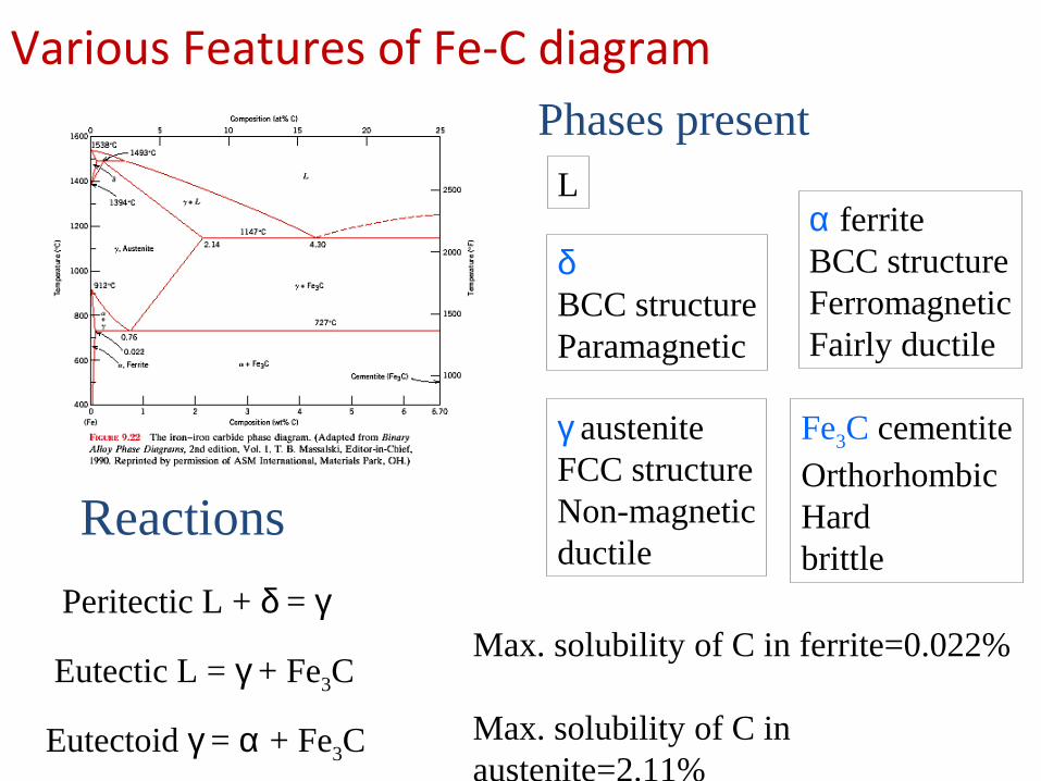
Various Features of Fe-C diagram
Peritectic L + δ = γ
Eutectic L = γ + Fe3C
Eutectoid γ = α + Fe3C
Phases present L
Reactions
δBCC structureParamagnetic
γ austeniteFCC structureNon-magneticductile
α ferriteBCC structureFerromagneticFairly ductile
Fe3C cementiteOrthorhombicHardbrittle
Max. solubility of C in ferrite=0.022%
Max. solubility of C in austenite=2.11%
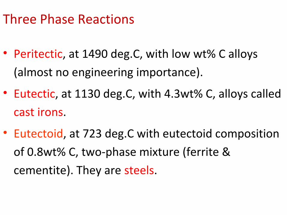
Three Phase Reactions
• Peritectic, at 1490 deg.C, with low wt% C alloys
(almost no engineering importance).
• Eutectic, at 1130 deg.C, with 4.3wt% C, alloys called
cast irons.
• Eutectoid, at 723 deg.C with eutectoid composition
of 0.8wt% C, two-phase mixture (ferrite &
cementite). They are steels.
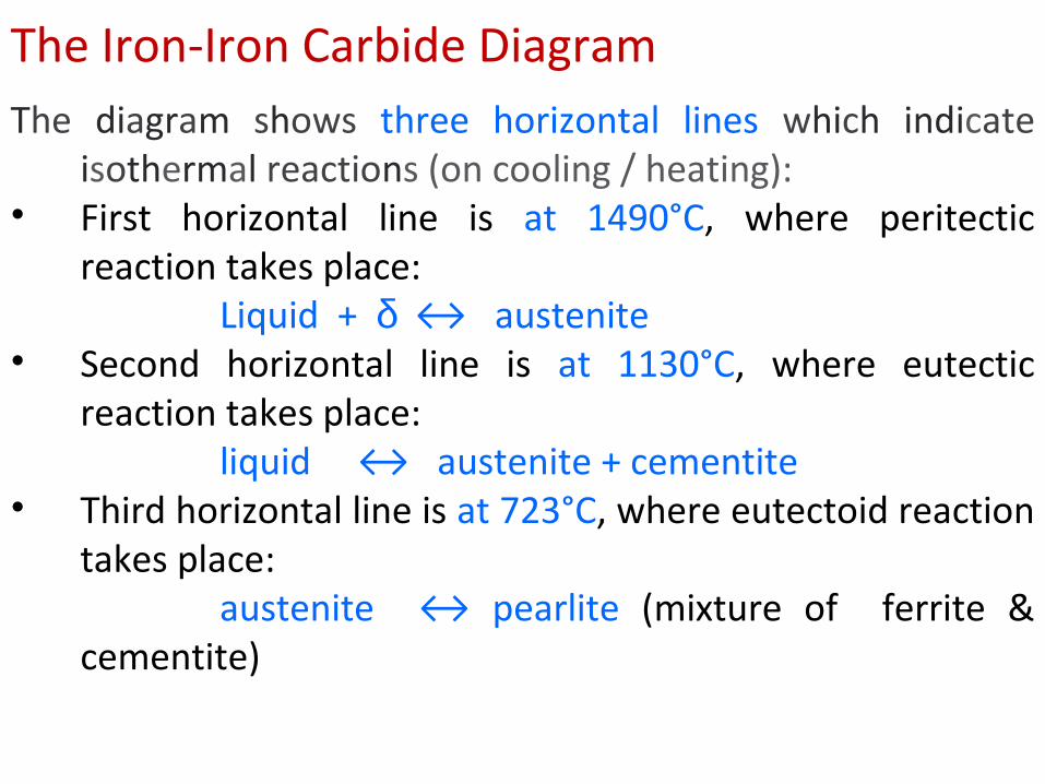
The Iron-Iron Carbide DiagramThe diagram shows three horizontal lines which indicate
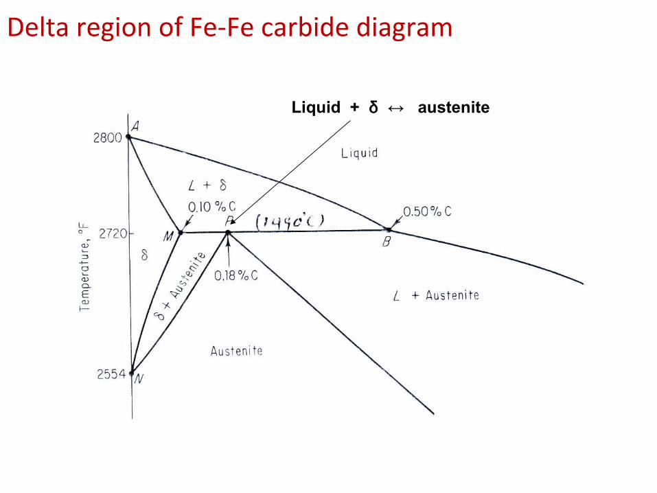
isothermal reactions (on cooling / heating): • First horizontal line is at 1490°C, where peritectic
reaction takes place: Liquid + δ ↔ austenite
• Second horizontal line is at 1130°C, where eutectic reaction takes place:
liquid ↔ austenite + cementite• Third horizontal line is at 723°C, where eutectoid reaction
takes place:austenite ↔ pearlite (mixture of ferrite &
cementite)
Delta region of Fe-Fe carbide diagram
Liquid + δ ↔ austenite
Ferrite region of Fe-Fe Carbide diagram
The Austenite to ferrite / cementite transformation in relation to Fe-C diagram

The Austenite to ferrite / cementite transformation in relation to Fe-C diagram
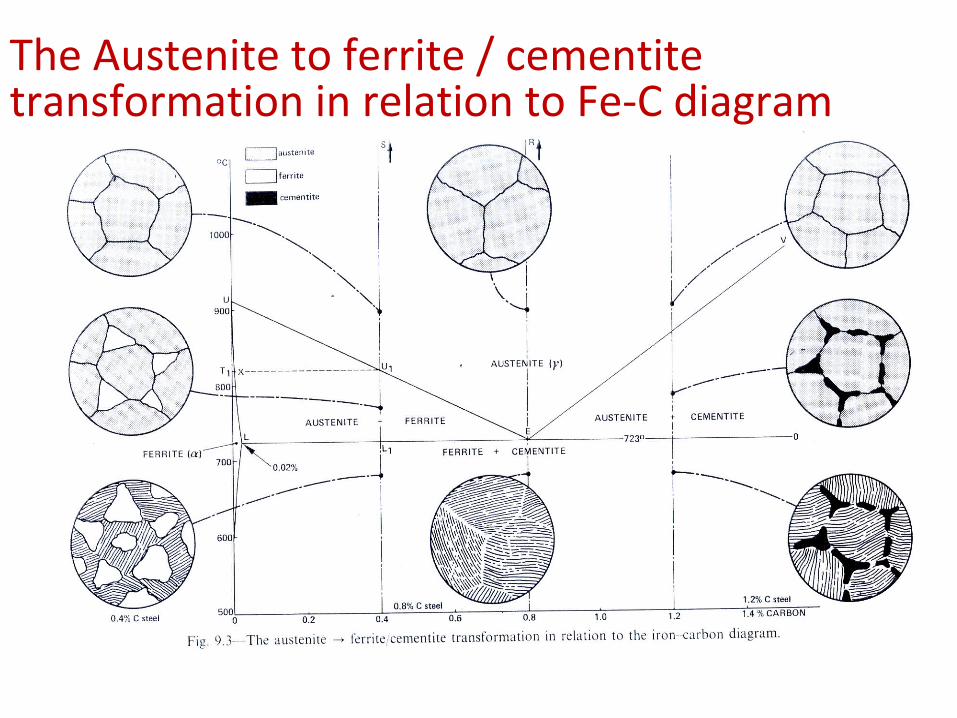
In order to understand the transformation processes,
consider a steel of the eutectoid composition. 0.8% carbon,
being slow cooled along line x-x‘.
• At the upper temperatures, only austenite is present, with
the 0.8% carbon being dissolved in solid solution within the
FCC. When the steel cools through 723°C, several changes
occur simultaneously.
The Austenite to ferrite / cementite transformation in relation to Fe-C diagram• The iron wants to change crystal structure from the FCC
austenite to the BCC ferrite, but the ferrite can only
contain 0.02% carbon in solid solution.
• The excess carbon is rejected and forms the carbon-rich
intermetallic known as cementite.
The Austenite to ferrite / cementite transformation in relation to Fe-C diagram
• Hypo-eutectoid steels: Steels having less than 0.8% carbon are called hypo-eutectoid steels (hypo means "less than").
• Consider the cooling of a typical hypo-eutectoid alloy along line y-y‘.
• At high temperatures the material is entirely austenite.• Upon cooling it enters a region where the stable phases are
ferrite and austenite.• The low-carbon ferrite nucleates and grows, leaving the
remaining austenite richer in carbon.
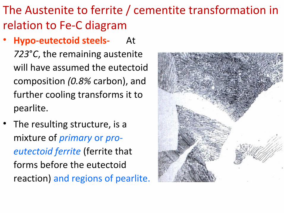
The Austenite to ferrite / cementite transformation in relation to Fe-C diagram• Hypo-eutectoid steels- At
723°C, the remaining austenite will have assumed the eutectoid composition (0.8% carbon), and further cooling transforms it to pearlite.
• The resulting structure, is a mixture of primary or pro-eutectoid ferrite (ferrite that forms before the eutectoid reaction) and regions of pearlite.
The Austenite to ferrite / cementite transformation in relation to Fe-C diagram
• Hyper-eutectoid steels (hyper means "greater than")
are those that contain more than the eutectoid amount of
Carbon.
• When such a steel cools, as along line z-z' , the process is
similar to the hypo-eutectoid steel, except that the primary
or pro-eutectoid phase is now cementite instead of ferrite.
The Austenite to ferrite / cementite transformation in relation to Fe-C diagram
• As the carbon-rich phase nucleates and grows, the
remaining austenite decreases in carbon content, again
reaching the eutectoid composition at 723°C.
• This austenite transforms to pearlite upon slow cooling
through the eutectoid temperature.
• The resulting structure consists of primary cementite and
pearlite.
• The continuous network of primary cementite will cause
the material to be extremely brittle.

The Austenite to ferrite / cementite transformation in relation to Fe-C diagram
Hypo-eutectoid steel showing primary cementite along grain boundaries pearlite
The Austenite to ferrite / cementite transformation in relation to Fe-C diagram
• When the alloys are cooled rapidly, entirely
different results are obtained, since sufficient time
may not be provided for the normal phase
reactions to occur.
• In these cases, the equilibrium phase diagram is no
longer a valid tool for engineering analysis.
• Rapid-cool processes are important in the heat
treatment of steels and other metals (to be
discussed later in H/T of steels).
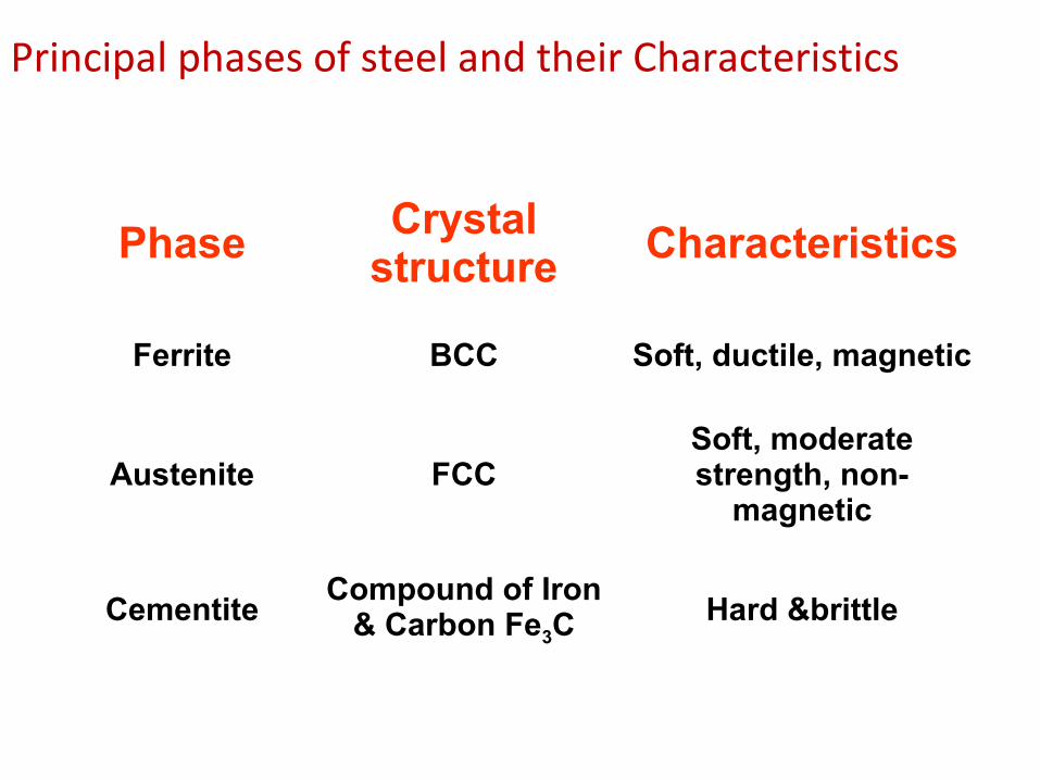
Principal phases of steel and their Characteristics
PhaseCrystal
structure Characteristics
Ferrite BCC Soft, ductile, magnetic
Austenite FCCSoft, moderate strength, non-
magnetic
CementiteCompound of Iron
& Carbon Fe3CHard &brittle

Thank You.!