
Introduction to Leveling · 2019-11-05 · DO NOT DROP RODS!! Keep one hand on rod at all times...
50
Differential and Trigonometric Introduction to Leveling
Transcript of Introduction to Leveling · 2019-11-05 · DO NOT DROP RODS!! Keep one hand on rod at all times...
Differential and Trigonometric
Introduction to Leveling
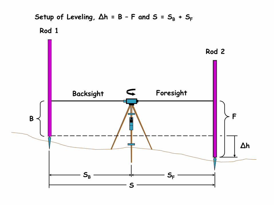
Rod 1
Rod 2
B
Backsight Foresight
F
Δh
SB
S
SF
Setup of Leveling, Δh = B – F and S = SB + SF
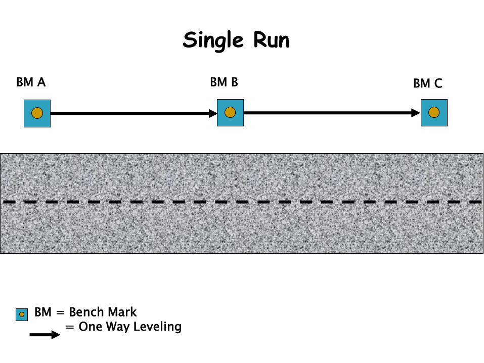
Single Run
BM A BM C BM B
BM = Bench Mark = One Way Leveling
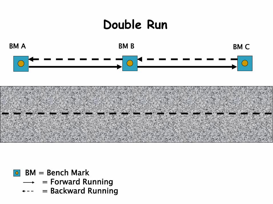
Double Run
BM A BM C BM B
BM = Bench Mark = Forward Running = Backward Running
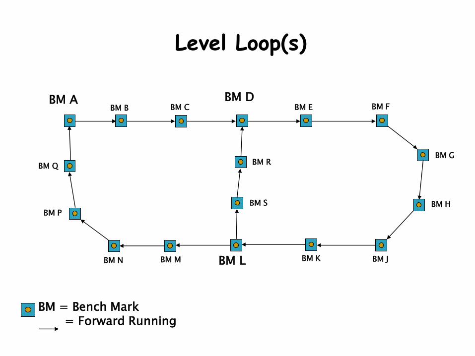
Level Loop(s)
BM A BM D
BM L
BM B
BM R
BM S
BM K BM J
BM H
BM G
BM F BM E BM C
BM M BM N
BM P
BM Q
BM = Bench Mark = Forward Running
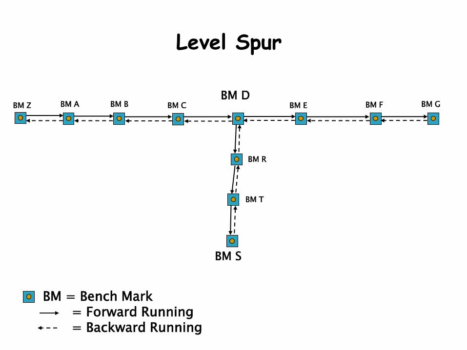
Level Spur
BM A BM D
BM S
BM B
BM R
BM T
BM F BM E BM C BM Z BM G
BM = Bench Mark = Forward Running = Backward Running
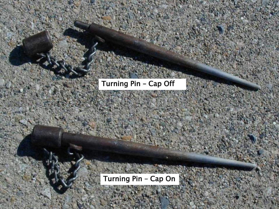
Turning Pin – Cap Off
Turning Pin – Cap On
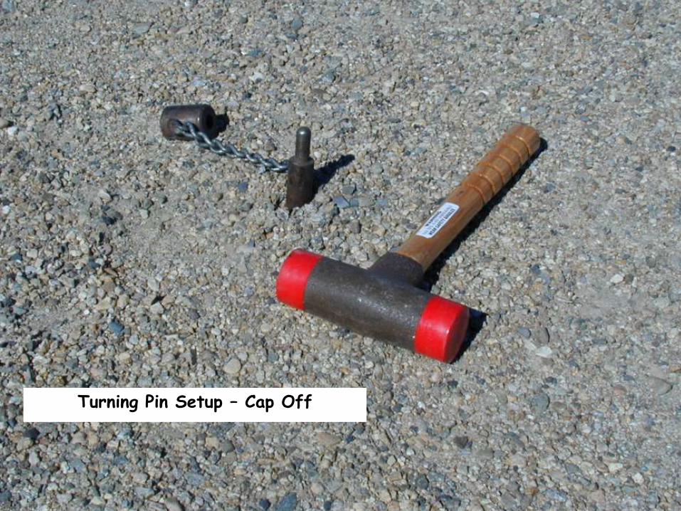
Turning Pin Setup – Cap Off
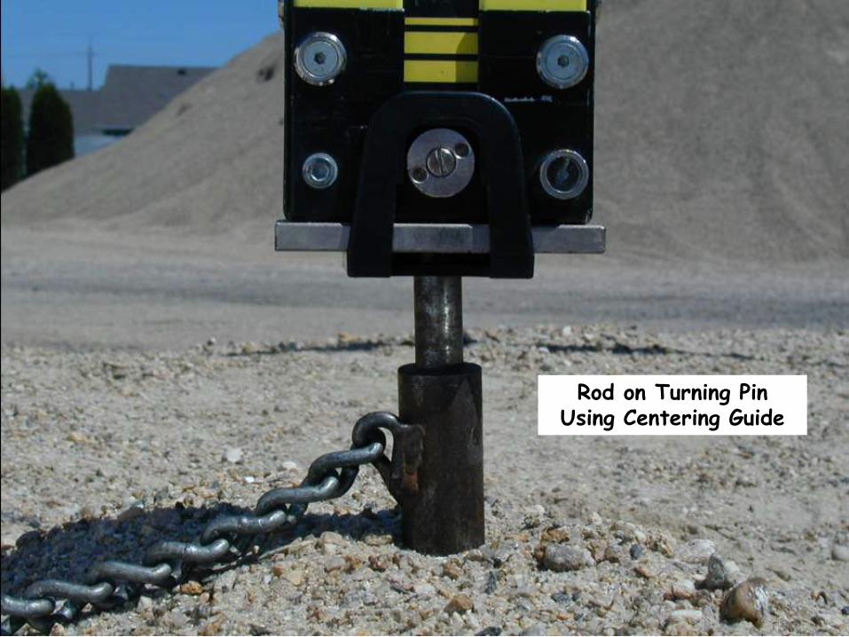
Rod on Turning Pin Using Centering Guide
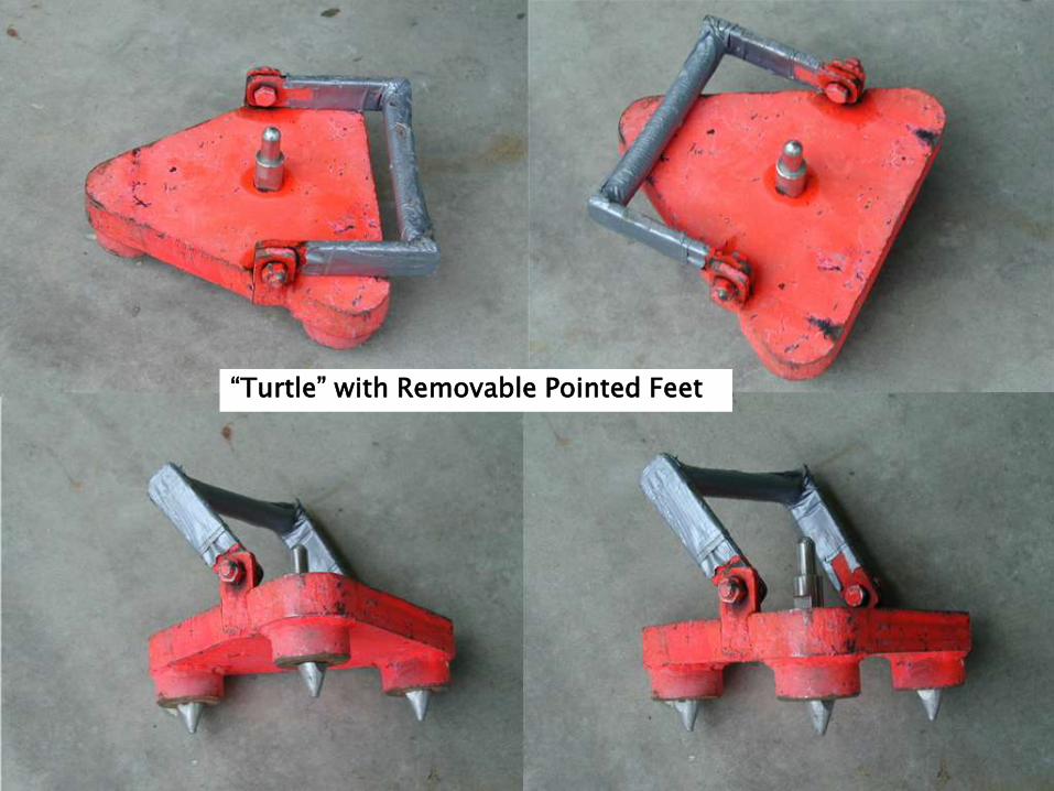
“Turtle” with Removable Pointed Feet
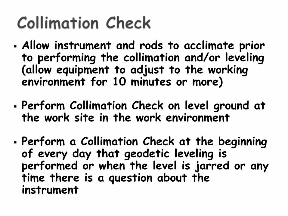
Allow instrument and rods to acclimate prior to performing the collimation and/or leveling (allow equipment to adjust to the working environment for 10 minutes or more)
Perform Collimation Check on level ground at the work site in the work environment
Perform a Collimation Check at the beginning of every day that geodetic leveling is performed or when the level is jarred or any time there is a question about the instrument
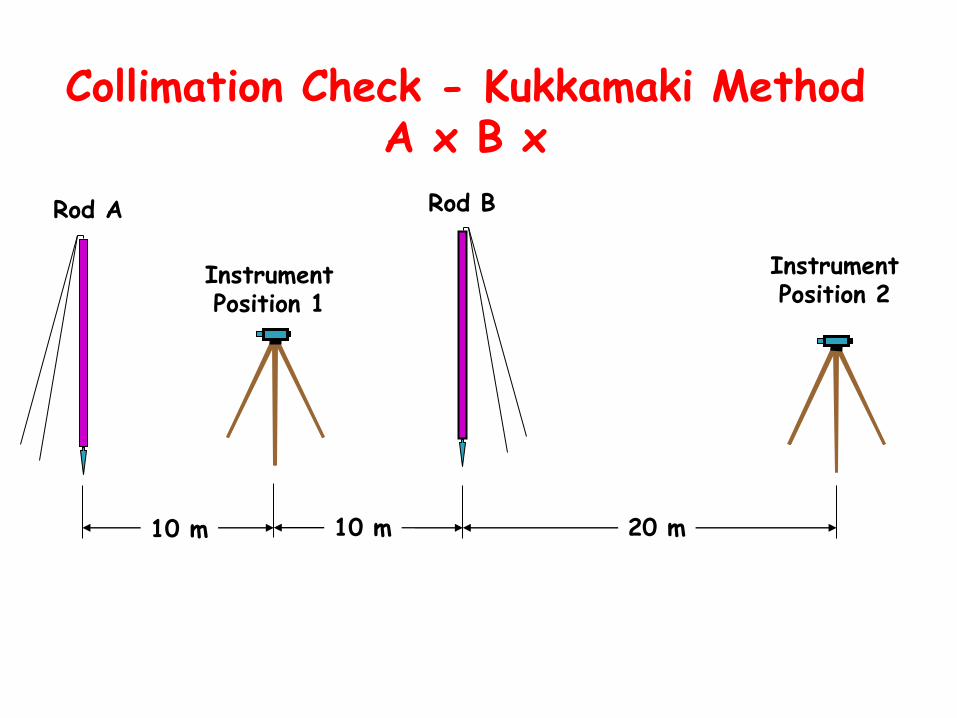
Collimation Check - Kukkamaki Method A x B x
10 m 10 m 20 m
Instrument Position 1
Instrument Position 2
Rod A Rod B
10 m
Rod A Rod B
Instrument Position 1
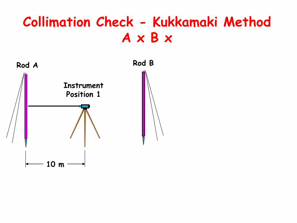
Collimation Check - Kukkamaki Method A x B x
10 m
Rod A Rod B
Instrument Position 1
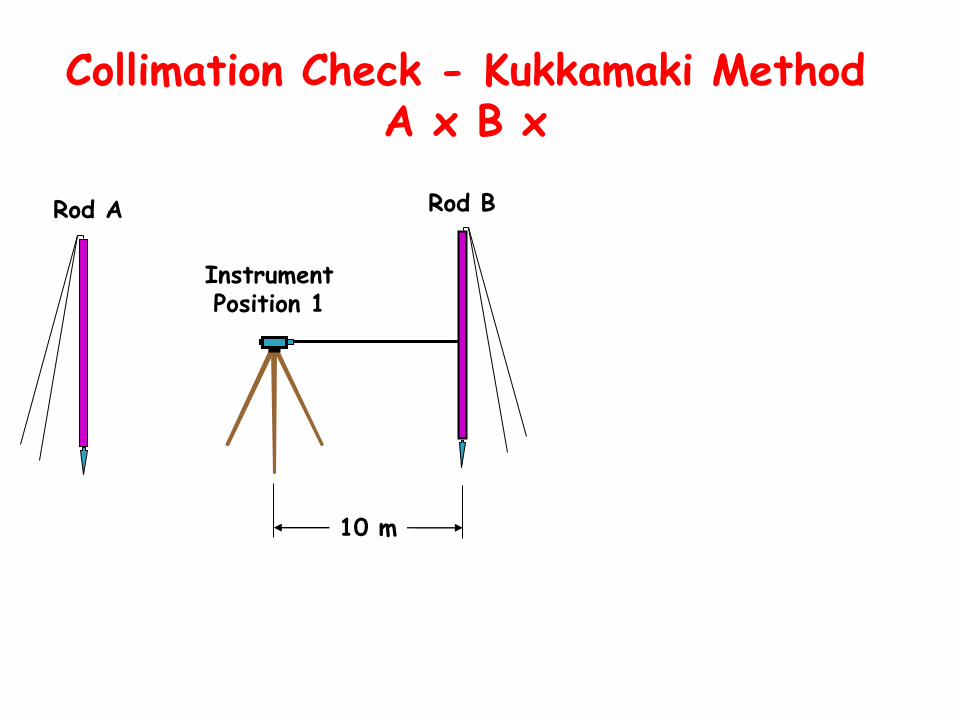
Collimation Check - Kukkamaki Method A x B x
20 m
Rod A Rod B
Instrument Position 2
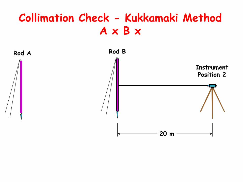
Collimation Check - Kukkamaki Method A x B x
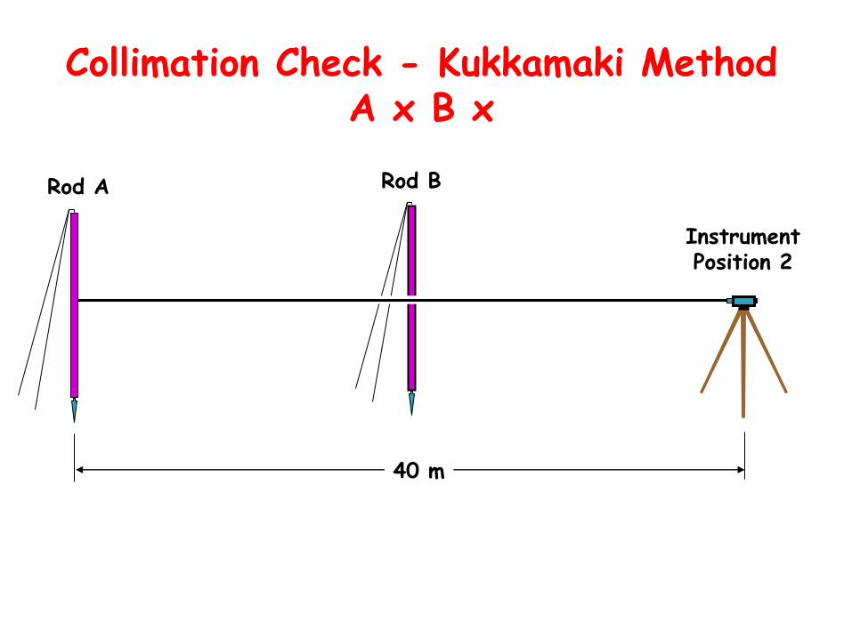
40 m
Rod A Rod B
Instrument Position 2
Collimation Check - Kukkamaki Method A x B x
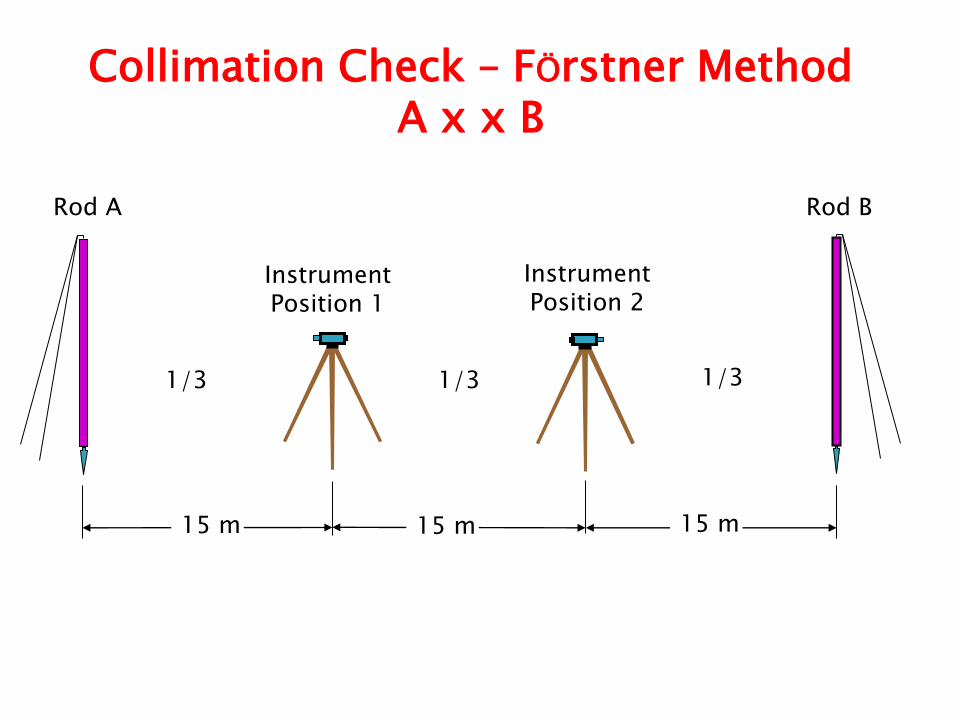
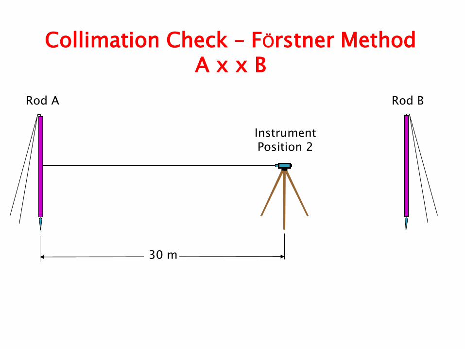
Collimation Check – FÖrstner Method A x x B
15 m 15 m 15 m
Instrument Position 1
Instrument Position 2
Rod A Rod B
1/3 1/3 1/3
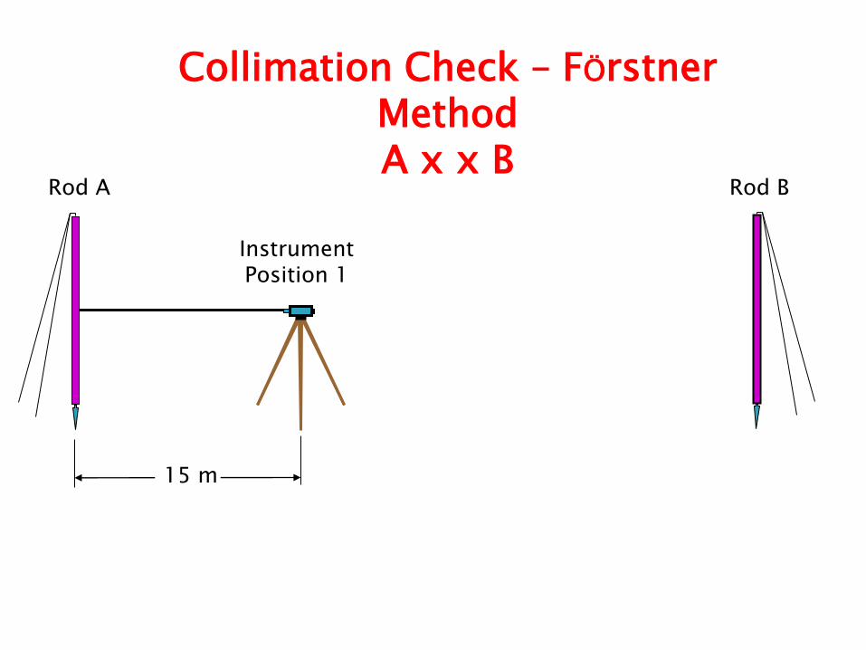
15 m
Instrument Position 1
Rod A Rod B
Collimation Check – FÖrstner Method A x x B
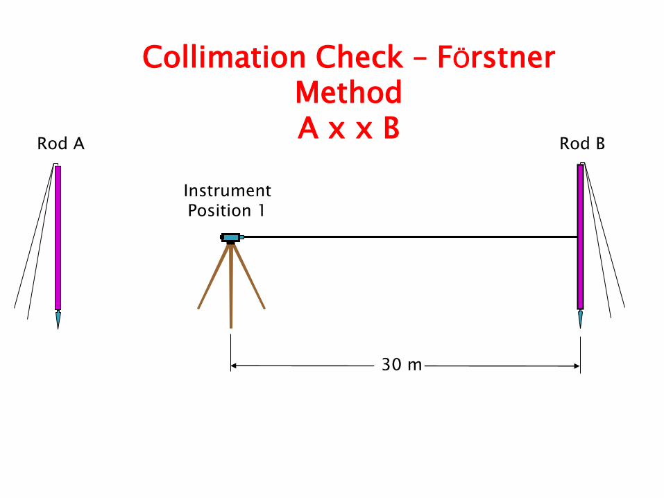
30 m
Instrument Position 1
Rod A Rod B
Collimation Check – FÖrstner Method A x x B
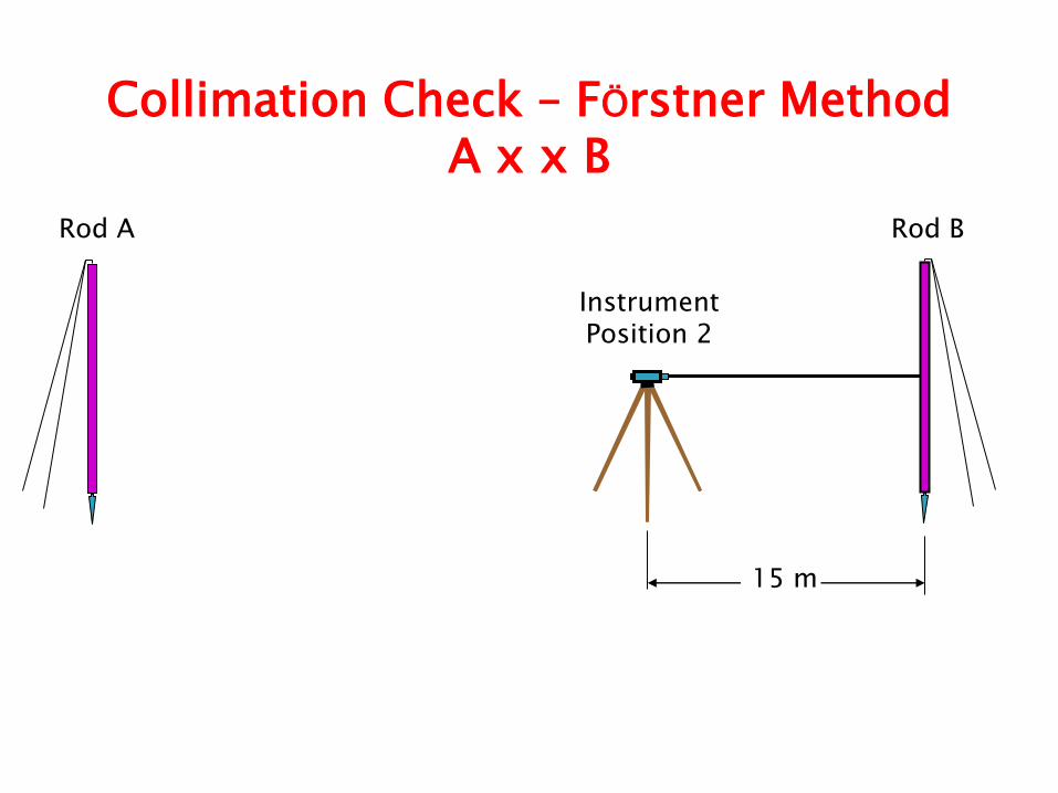
15 m
Instrument Position 2
Rod A Rod B
Collimation Check – FÖrstner Method A x x B
30 m
Instrument Position 2
Rod A Rod B
Collimation Check – FÖrstner Method A x x B
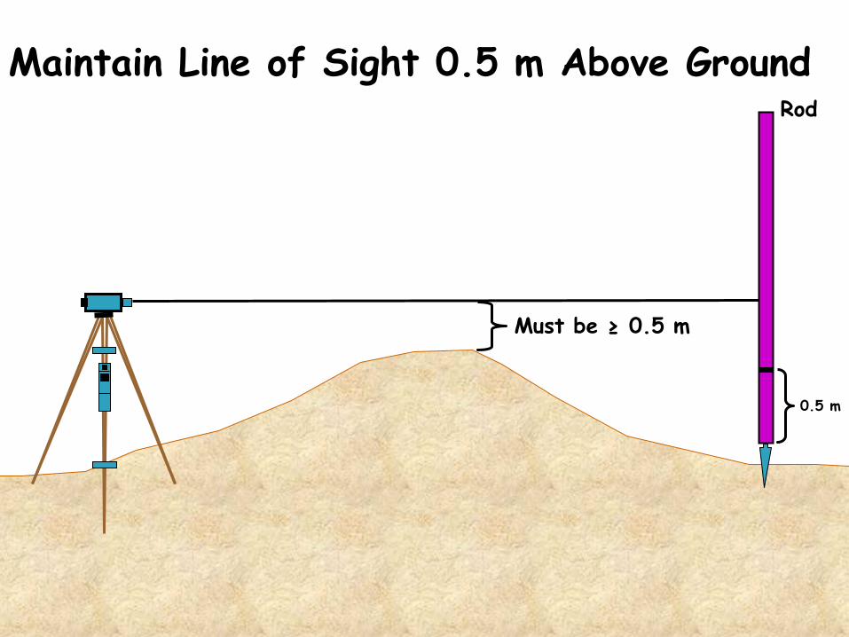
Maintain Line of Sight 0.5 m Above Ground Rod
0.5 m
Must be ≥ 0.5 m
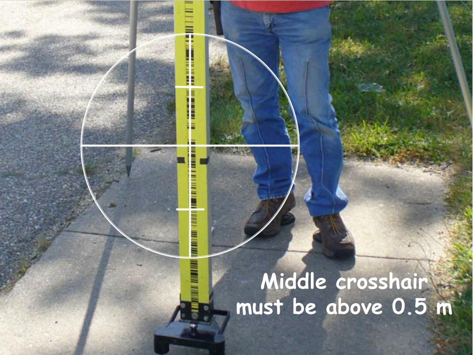
Middle crosshair must be above 0.5 m
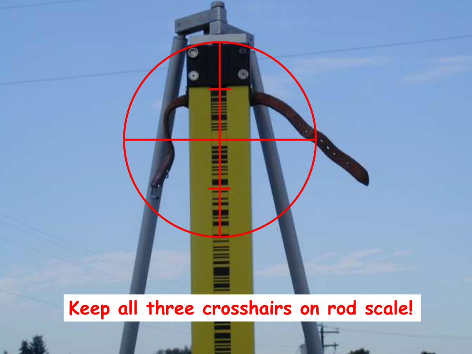
Keep all three crosshairs on rod scale!
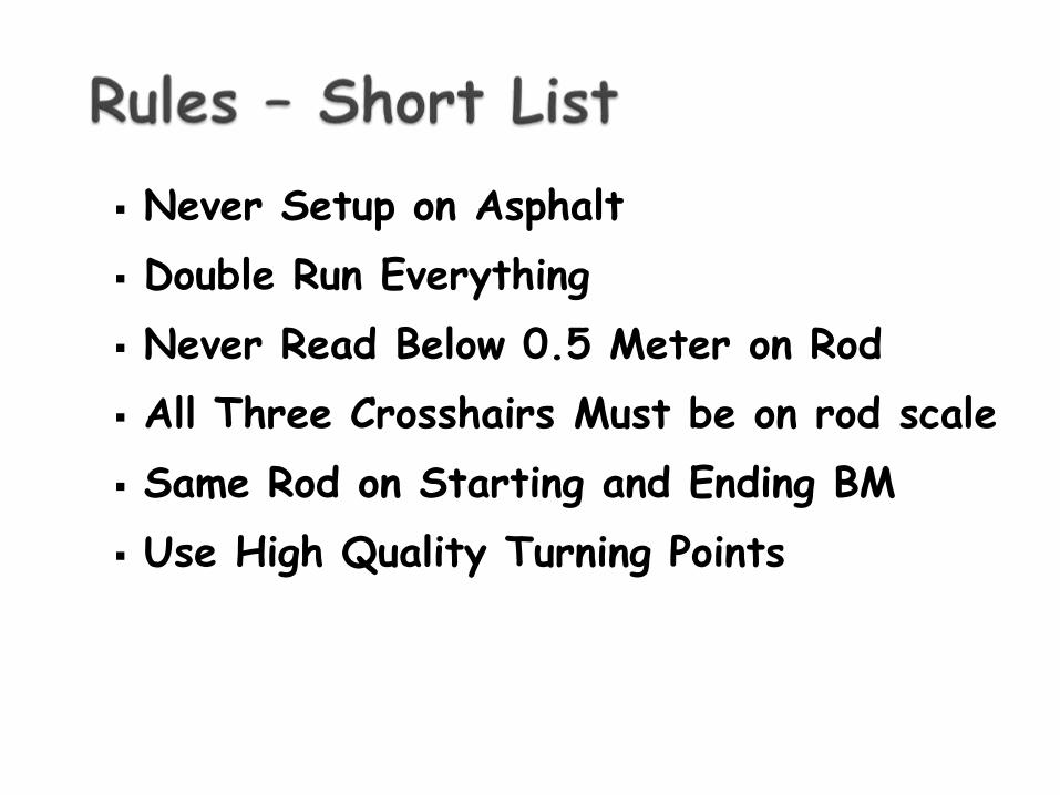
Never Setup on Asphalt
Double Run Everything
Never Read Below 0.5 Meter on Rod
All Three Crosshairs Must be on rod scale
Same Rod on Starting and Ending BM
Use High Quality Turning Points
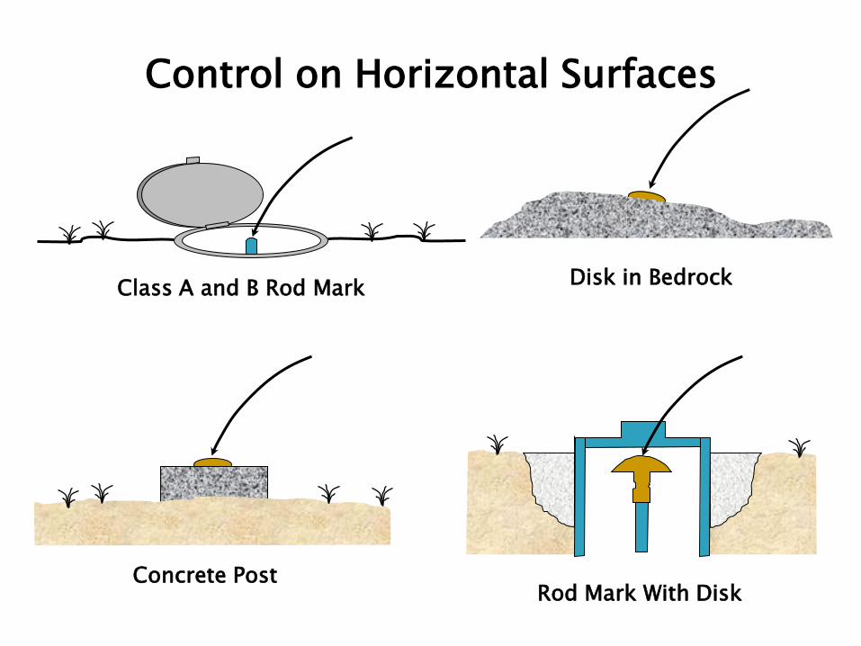
Rod Mark With Disk
Disk in Bedrock
Concrete Post
Class A and B Rod Mark
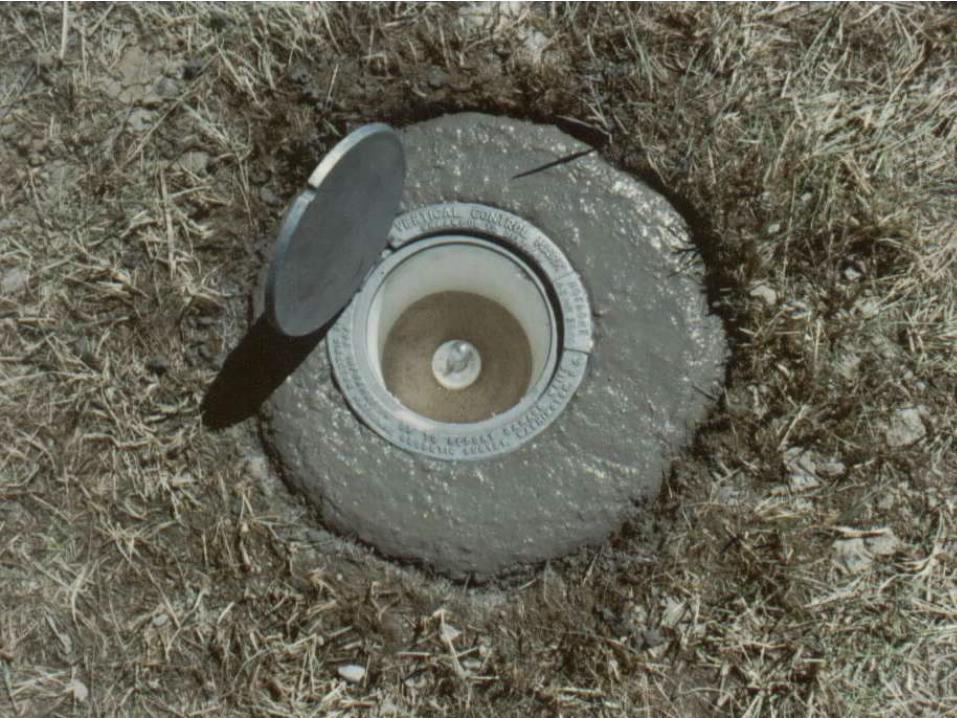
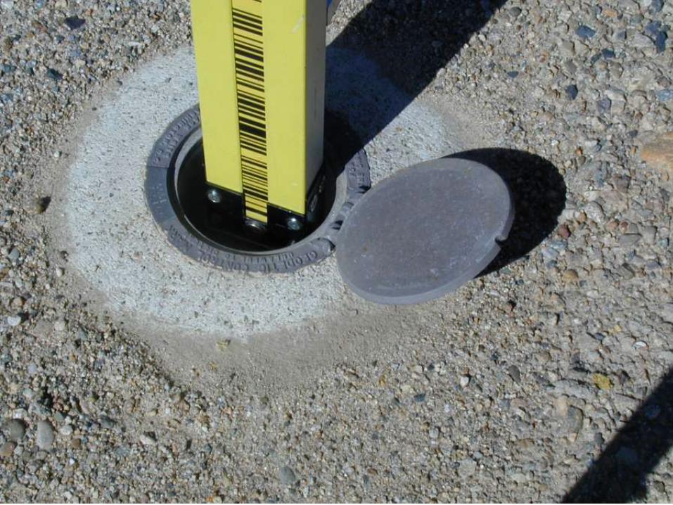
Control on Horizontal Surfaces
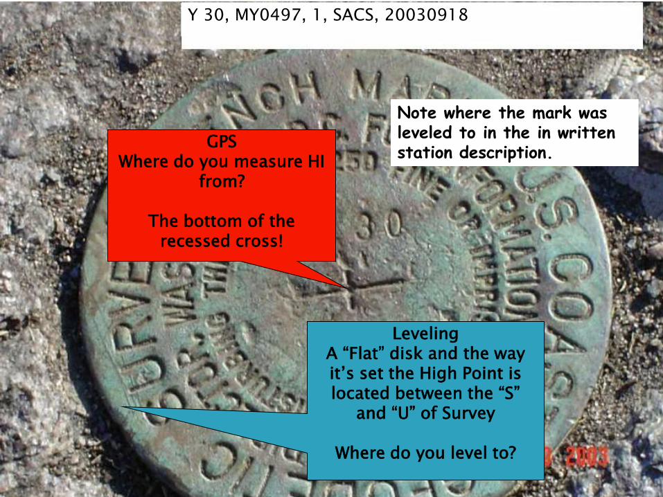
Y 30, MY0497, 1, SACS, 20030918
Leveling A “Flat” disk and the way it’s set the High Point is located between the “S”
and “U” of Survey
Where do you level to?
GPS Where do you measure HI
from?
The bottom of the recessed cross!
Note where the mark was leveled to in the in written station description.
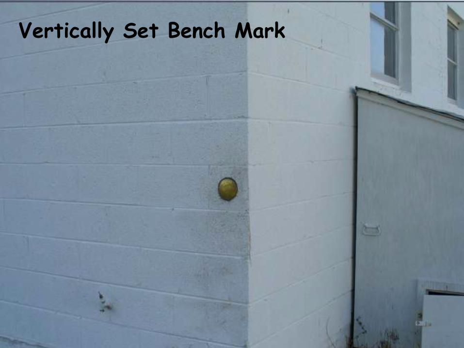
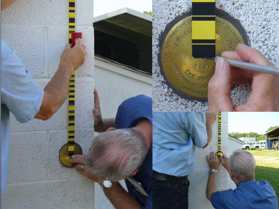
Vertically Set Bench Mark
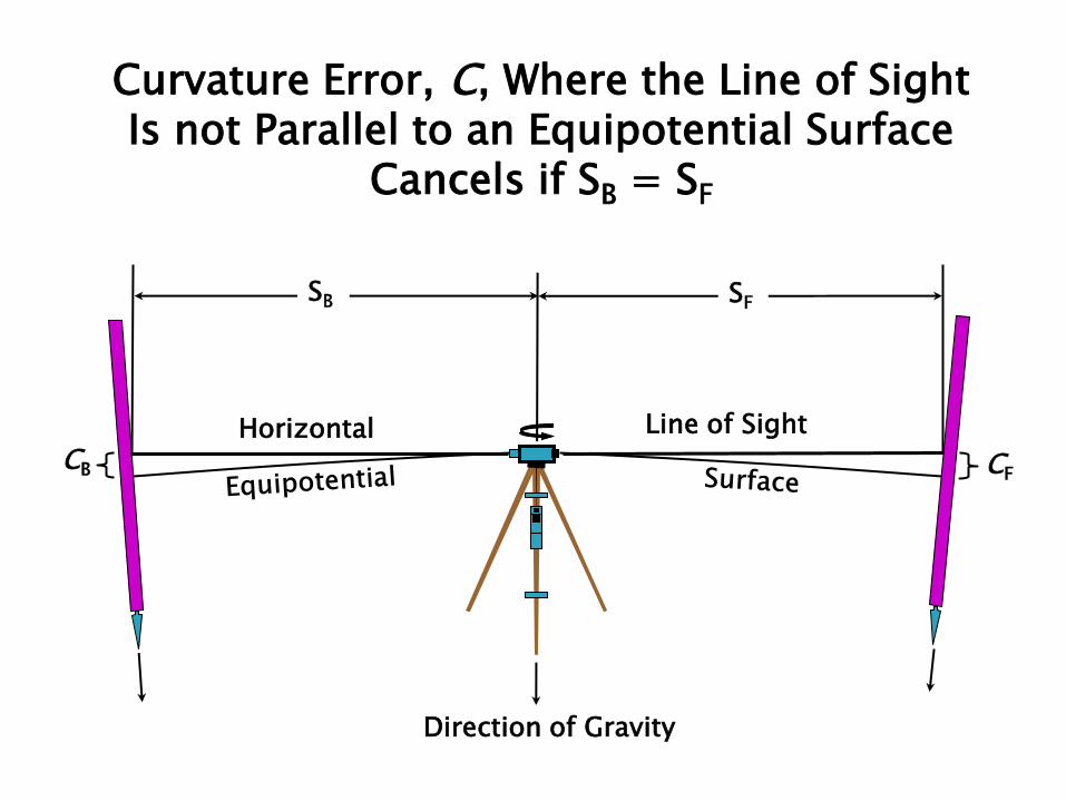
Curvature Error, C, Where the Line of Sight Is not Parallel to an Equipotential Surface
Cancels if SB = SF
Direction of Gravity
SF SB
CB CF
Horizontal Line of Sight
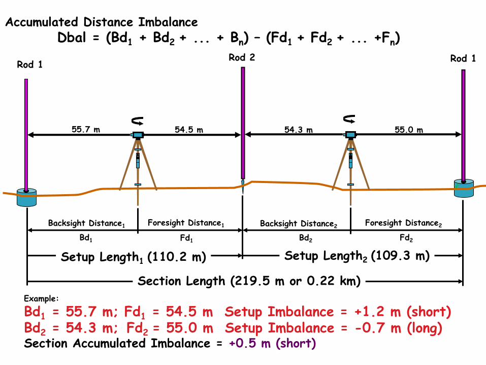
Accumulated Distance Imbalance Dbal = (Bd1 + Bd2 + ... + Bn) – (Fd1 + Fd2 + ... +Fn)
Rod 1 Rod 2 Rod 1
Section Length (219.5 m or 0.22 km)
Backsight Distance1 Foresight Distance1
Setup Length1 (110.2 m) Setup Length2 (109.3 m)
Backsight Distance2 Foresight Distance2
Example:
Bd1 = 55.7 m; Fd1 = 54.5 m Setup Imbalance = +1.2 m (short) Bd2 = 54.3 m; Fd2 = 55.0 m Setup Imbalance = -0.7 m (long) Section Accumulated Imbalance = +0.5 m (short)
55.7 m 54.5 m 54.3 m 55.0 m
Bd1 Fd1 Bd2 Fd2
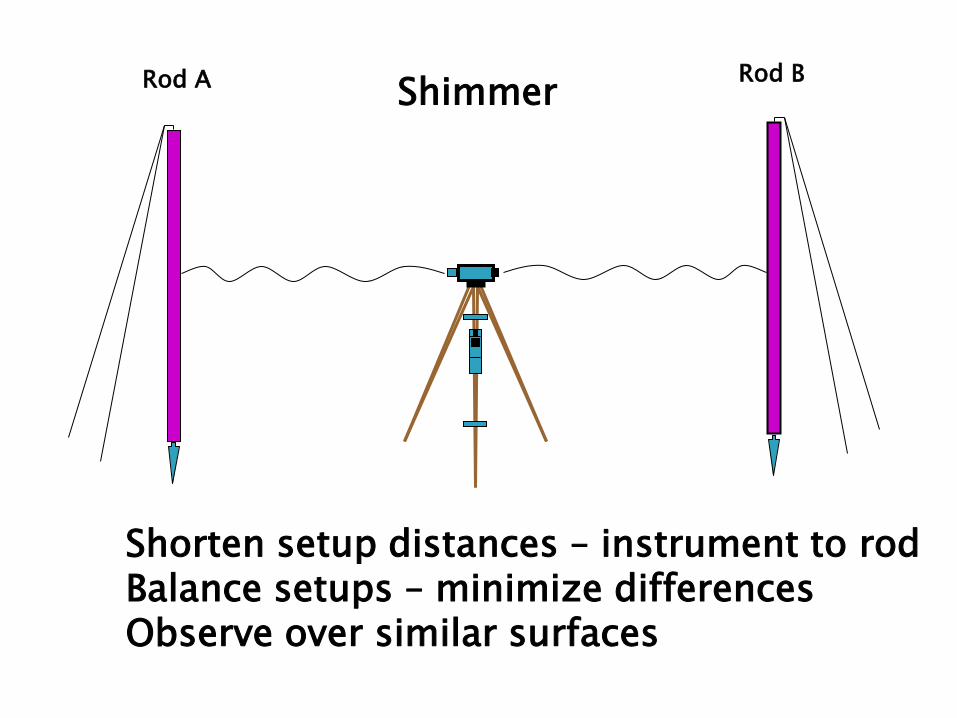
Rod A Rod B Shimmer
Shorten setup distances – instrument to rod Balance setups – minimize differences Observe over similar surfaces
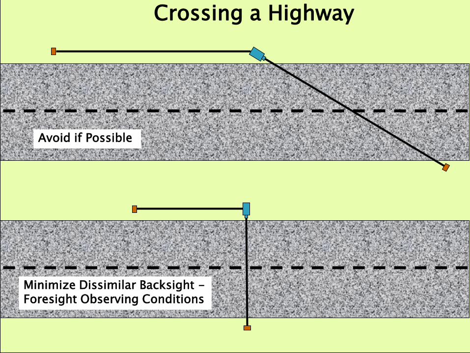
Crossing a Highway
Minimize Dissimilar Backsight - Foresight Observing Conditions
Avoid if Possible
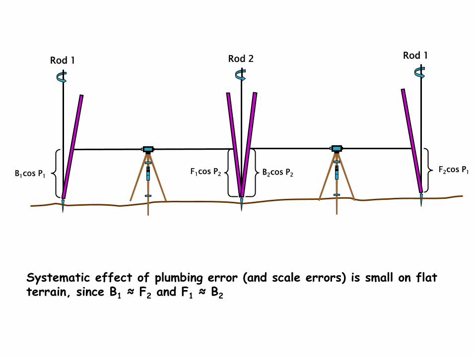
F1cos P2 B2cos P2 B1cos P1
Rod 1 Rod 2 Rod 1
F2cos P1
Systematic effect of plumbing error (and scale errors) is small on flat terrain, since B1 ≈ F2 and F1 ≈ B2
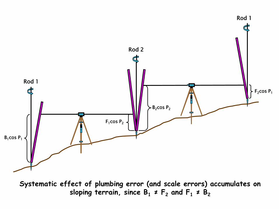
F2cos P1
Systematic effect of plumbing error (and scale errors) accumulates on sloping terrain, since B1 ≠ F2 and F1 ≠ B2
B1cos P1
Rod 1
F1cos P2
B2cos P2
Rod 2
Rod 1
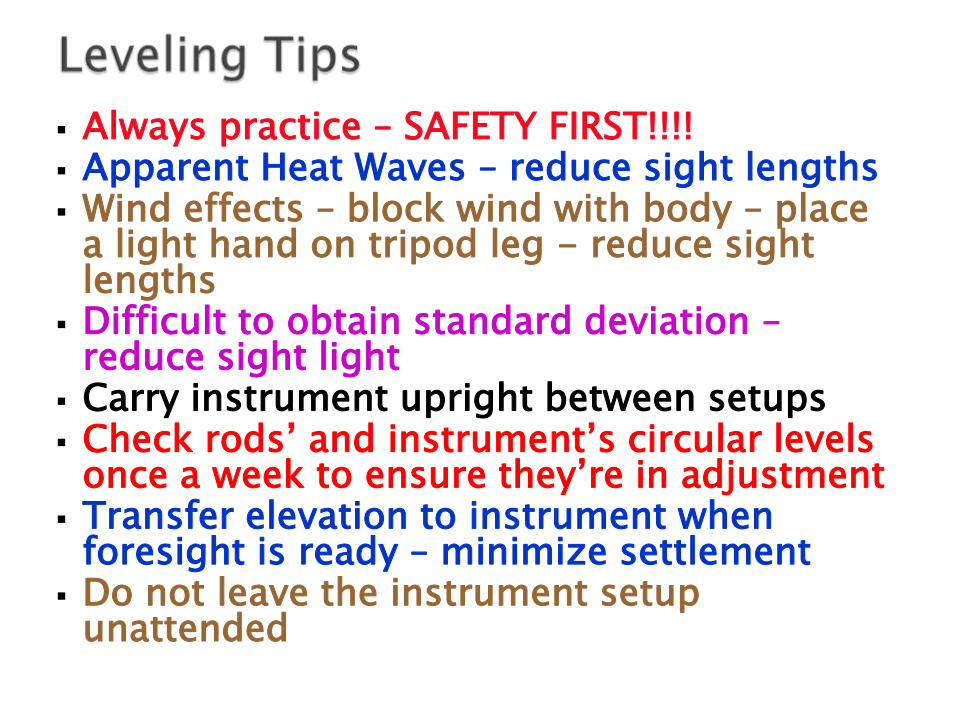
Always practice – SAFETY FIRST!!!! Apparent Heat Waves – reduce sight lengths Wind effects – block wind with body – place
a light hand on tripod leg - reduce sight lengths
Difficult to obtain standard deviation – reduce sight light
Carry instrument upright between setups Check rods’ and instrument’s circular levels
once a week to ensure they’re in adjustment Transfer elevation to instrument when
foresight is ready – minimize settlement Do not leave the instrument setup
unattended
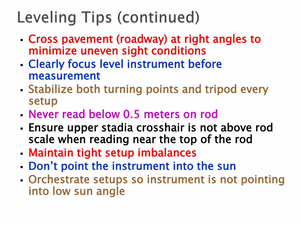
Cross pavement (roadway) at right angles to minimize uneven sight conditions
Clearly focus level instrument before measurement
Stabilize both turning points and tripod every setup
Never read below 0.5 meters on rod Ensure upper stadia crosshair is not above rod
scale when reading near the top of the rod
Maintain tight setup imbalances Don’t point the instrument into the sun Orchestrate setups so instrument is not pointing
into low sun angle
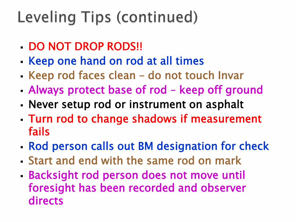
DO NOT DROP RODS!!
Keep one hand on rod at all times
Keep rod faces clean – do not touch Invar
Always protect base of rod – keep off ground
Never setup rod or instrument on asphalt
Turn rod to change shadows if measurement fails
Rod person calls out BM designation for check
Start and end with the same rod on mark
Backsight rod person does not move until foresight has been recorded and observer directs
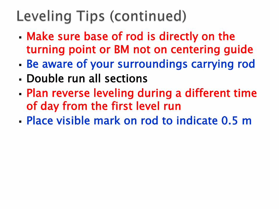
Make sure base of rod is directly on the turning point or BM not on centering guide
Be aware of your surroundings carrying rod
Double run all sections
Plan reverse leveling during a different time of day from the first level run
Place visible mark on rod to indicate 0.5 m
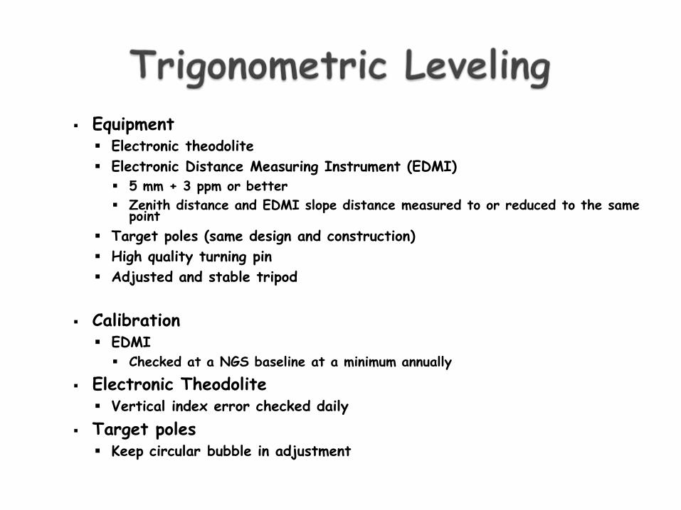
Equipment Electronic theodolite
Electronic Distance Measuring Instrument (EDMI)
5 mm + 3 ppm or better
Zenith distance and EDMI slope distance measured to or reduced to the same point
Target poles (same design and construction)
High quality turning pin
Adjusted and stable tripod
Calibration EDMI
Checked at a NGS baseline at a minimum annually
Electronic Theodolite Vertical index error checked daily
Target poles Keep circular bubble in adjustment
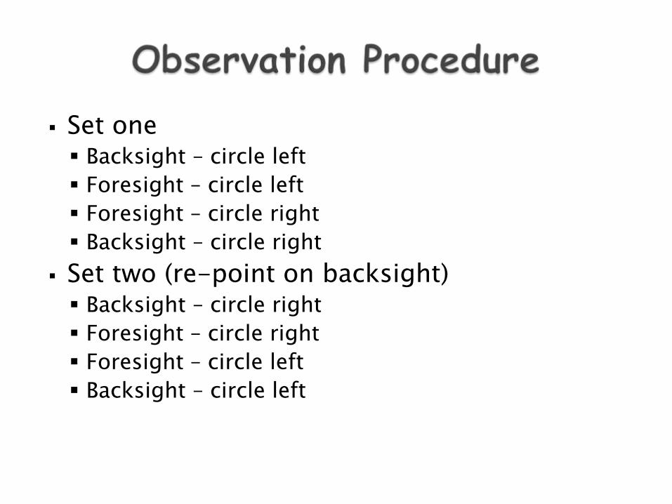
Set one Backsight – circle left
Foresight – circle left
Foresight – circle right
Backsight – circle right
Set two (re-point on backsight) Backsight – circle right
Foresight – circle right
Foresight – circle left
Backsight – circle left
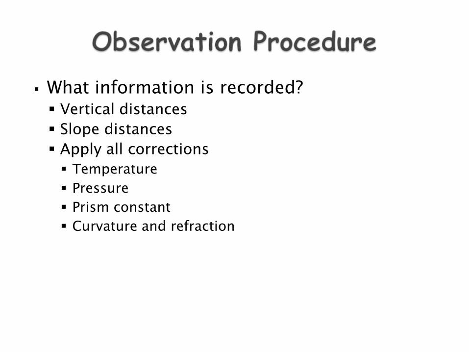
What information is recorded? Vertical distances
Slope distances
Apply all corrections
Temperature
Pressure
Prism constant
Curvature and refraction
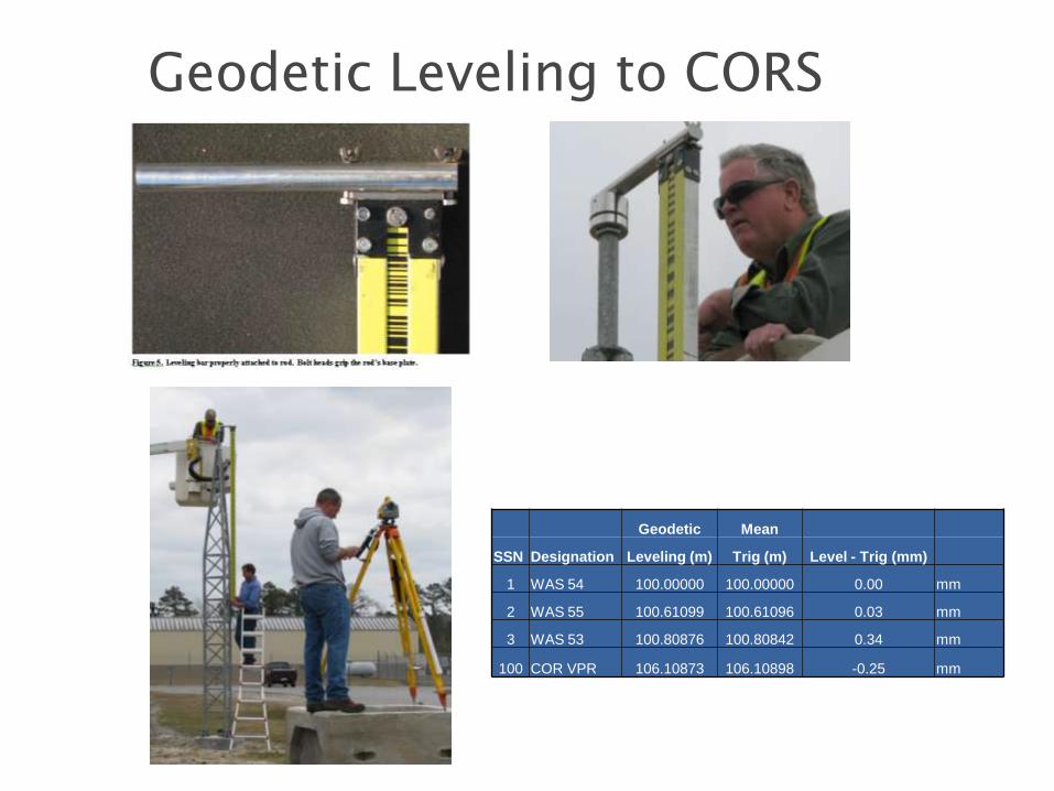
Geodetic Leveling to CORS ARP
Geodetic Mean
SSN Designation Leveling (m) Trig (m) Level - Trig (mm)
1 WAS 54 100.00000 100.00000 0.00 mm
2 WAS 55 100.61099 100.61096 0.03 mm
3 WAS 53 100.80876 100.80842 0.34 mm
100 COR VPR 106.10873 106.10898 -0.25 mm
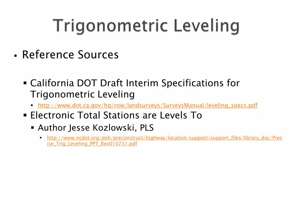
Reference Sources
California DOT Draft Interim Specifications for
Trigonometric Leveling http://www.dot.ca.gov/hq/row/landsurveys/SurveysManual/leveling_specs.pdf
Electronic Total Stations are Levels To
Author Jesse Kozlowski, PLS http://www.ncdot.org/doh/preconstruct/highway/location/support/support_files/library_doc/Prec
ise_Trig_Leveling_PPT_Rev010731.pdf
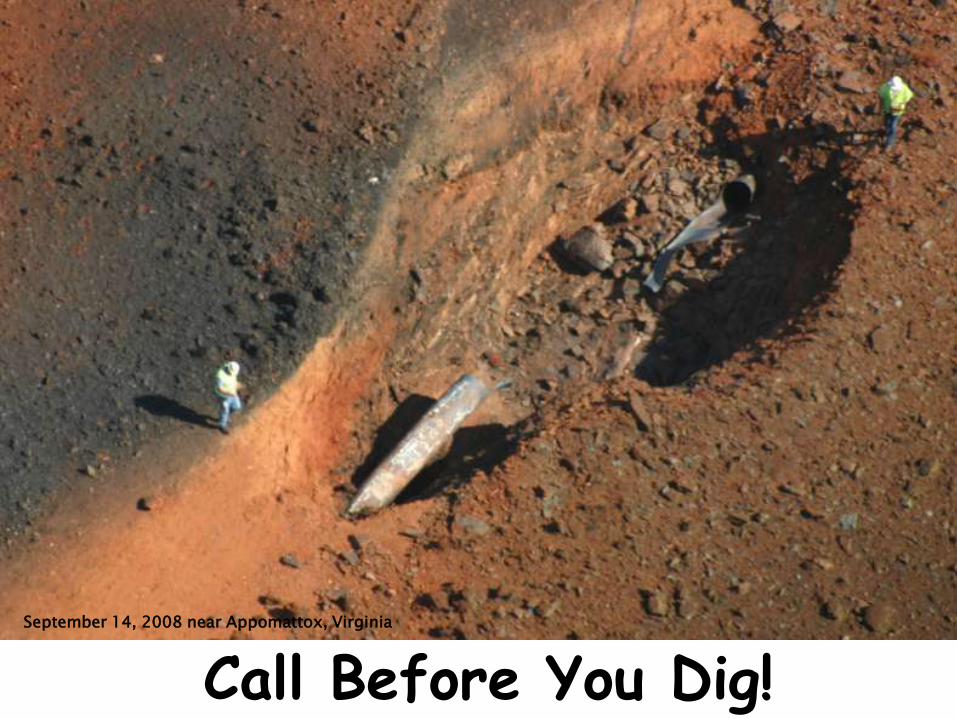
Call Before You Dig! September 14, 2008 near Appomattox, Virginia
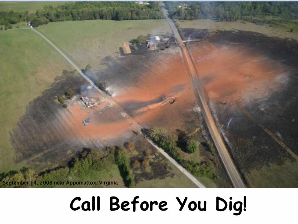
Call Before You Dig!
September 14, 2008 near Appomattox, Virginia

Gary Thompson, PLS NC Geodetic Survey 512 North Salisbury Street Raleigh, NC 27604 919-707-9230 phone [email protected]