Introduction of Damping Resistances in Simulations of ...
16
Introduction of Damping Resistances in Simulations of Electromagnetic Transients Using Alternate Structures Code: 19.009 Melissa de Oliveira Santos, Luis Henrique Jús, Thainá Guimarães Pereira, Aghatta Cioquetta Moreira, Afonso José do Prado UNESP, São João da Boa Vista, Brazil 13/11/2017 1
Transcript of Introduction of Damping Resistances in Simulations of ...
Introduction of Damping Resistances in
Simulations of Electromagnetic
Transients Using Alternate Structures
Code: 19.009
Melissa de Oliveira Santos, Luis Henrique Jús, Thainá
Guimarães Pereira, Aghatta Cioquetta Moreira, Afonso José
do Prado
UNESP, São João da Boa Vista, Brazil
13/11/2017 1
• Apply a different structure of π circuit in
cascade;
• Generate three-dimensional graphics that
show the behavior of the highest voltage
peak in the wave reflection;
• Compare with the model wich includes
damping resistance in all units of π circuits
in cascade;
• Check the results accuracy.
Objectives
13/11/2017 2
• Simulates long-range circuits (power) or circuits
that work in high frequency;
• Model transmission lines: π circuits in cascade;
• Digital simulations cause numerical errors;
• Numerical erros cause Gibbs oscillations;
• 𝑅𝐷 softens the oscillations;
• Initially, 𝑅𝐷 was introduced in all units of π circuits;
• Studies try to reduce computational time without
losing the accuracy.
Introduction
13/11/2017 3
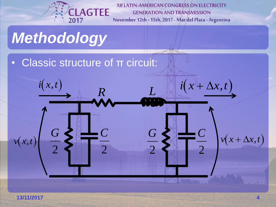
• Classic structure of π circuit:
Methodology
13/11/2017 4
G
2
C
2
R L
G
2
C
2 v x t, v x x t ,
i x t, i x x t ,
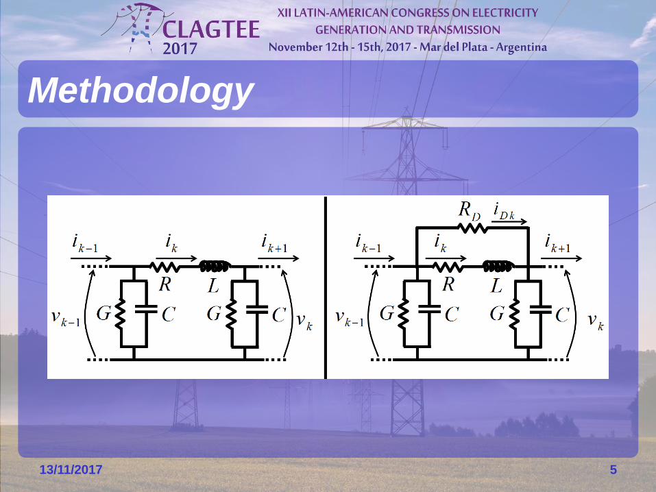
Methodology
13/11/2017 5
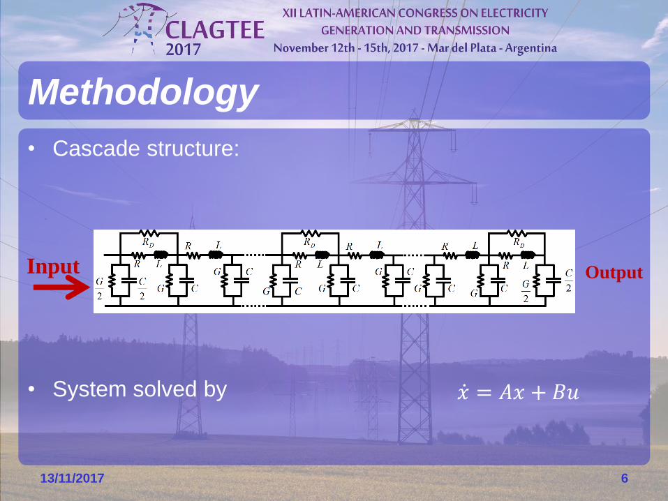
• Cascade structure:
• System solved by
Methodology
13/11/2017 6
Input Output
ሶ𝑥 = 𝐴𝑥 + 𝐵𝑢
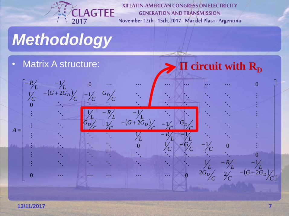
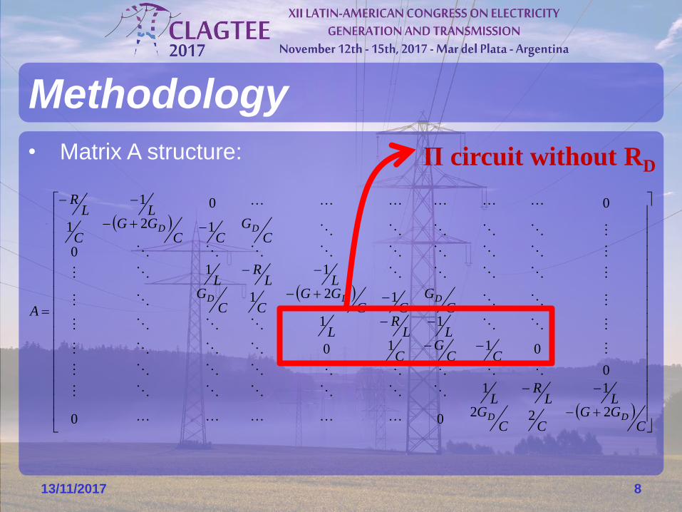
• Matrix A structure:
Methodology
13/11/2017 7
CGG
CCG
LLR
L
CCG
C
LLR
L
CG
CCGG
CCG
LLR
L
CG
CCGG
C
LLR
A
DD
DDD
DD
22200
11
0
0110
11
121
11
0
121
001
Π circuit with RD
• Matrix A structure:
Methodology
13/11/2017 8
CGG
CCG
LLR
L
CCG
C
LLR
L
CG
CCGG
CCG
LLR
L
CG
CCGG
C
LLR
A
DD
DDD
DD
22200
11
0
0110
11
121
11
0
121
001
Π circuit without RD
Methodology
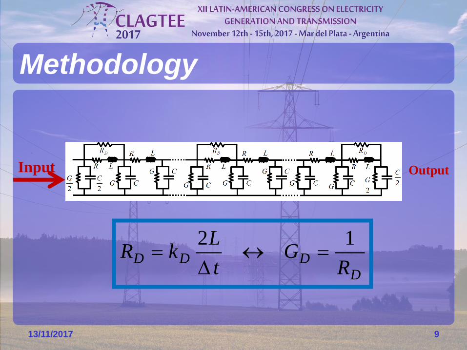
13/11/2017 9
Input Output
DDDD
RG
t
LkR
12
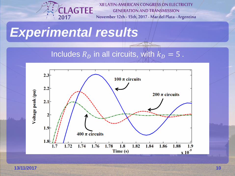
Includes 𝑅𝐷 in all circuits, with 𝑘𝐷 = 5 .
Experimental results
13/11/2017 10
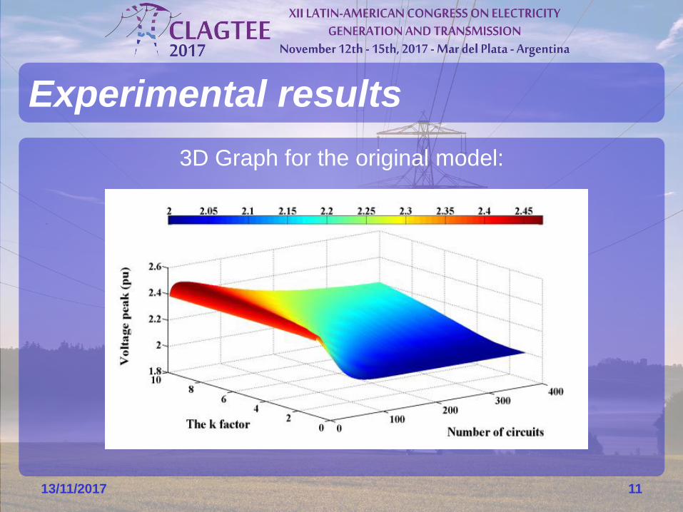
3D Graph for the original model:
Experimental results
13/11/2017 11
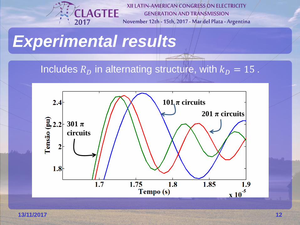
Includes 𝑅𝐷 in alternating structure, with 𝑘𝐷 = 15 .
Experimental results
13/11/2017 12
301 π
circuits
101 π circuits
201 π circuits
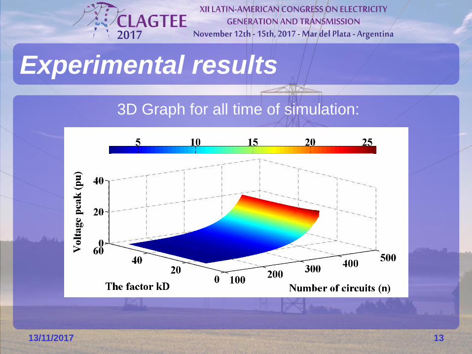
3D Graph for all time of simulation:
Experimental results
13/11/2017 13
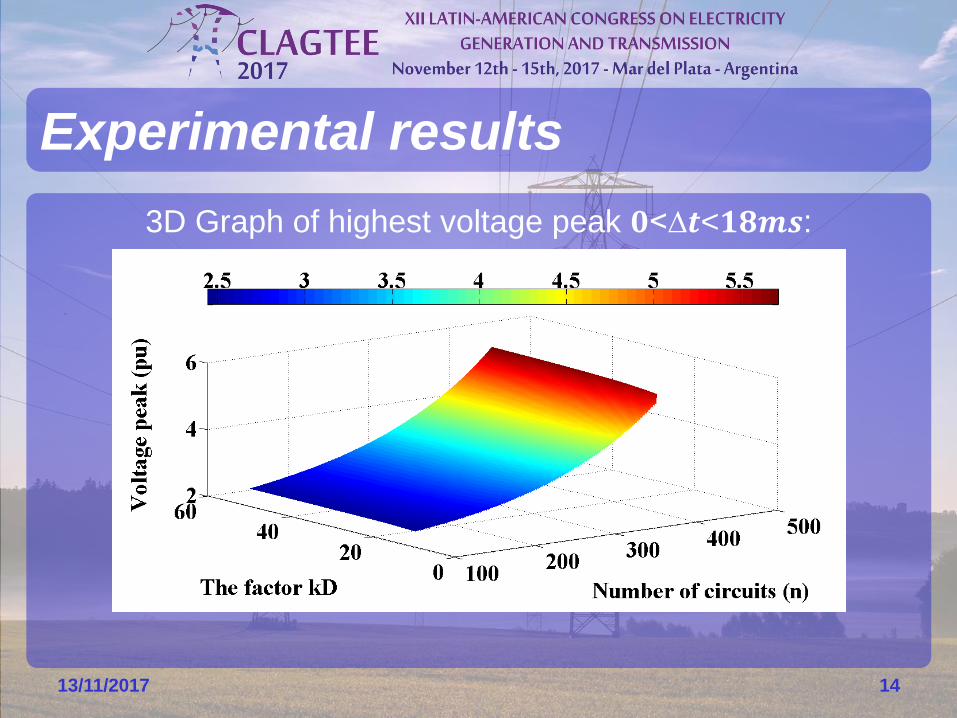
3D Graph of highest voltage peak 𝟎<∆𝒕<𝟏𝟖𝒎𝒔:
Experimental results
13/11/2017 14
• It is not possible to keep the accurate;
• 5% error in original model;
• 25% error in alternating structure
model;
• 20% error difference between the
models;
• 𝑅𝐷 aplication in all π circuits of cascade
still is a simple model better.
Conclusions
13/11/2017 15
Acknowledgments
13/11/2017 16
Process 2015/ 20684-7