CEPC booster and damping ring status
43
CEPC Parameter, Booster and Damping Ring Status Dou Wang on behalf of CEPC AP group Many Thanks to: K. Oide, M. Koratzinos, N. Iida IAS Program on High Energy Physics, Jan. 20-22, 2020. Hong Kong. HKUST Jockey Club Institute for Advanced Study
Transcript of CEPC booster and damping ring status
CEPC Parameter, Booster and Damping Ring Status
Dou Wangon behalf of CEPC AP group
Many Thanks to: K. Oide, M. Koratzinos, N. Iida
IAS Program on High Energy Physics, Jan. 20-22, 2020. Hong Kong.
HKUST Jockey Club Institute for Advanced Study

Outline
Booster progress
Damping ring progress
• Refine of CDR design
• Lower emittance booster study
• Feedback system design status
• Damping ring
• EC / BC2
New goals after CDR: higher lumi. for Higgs & Z
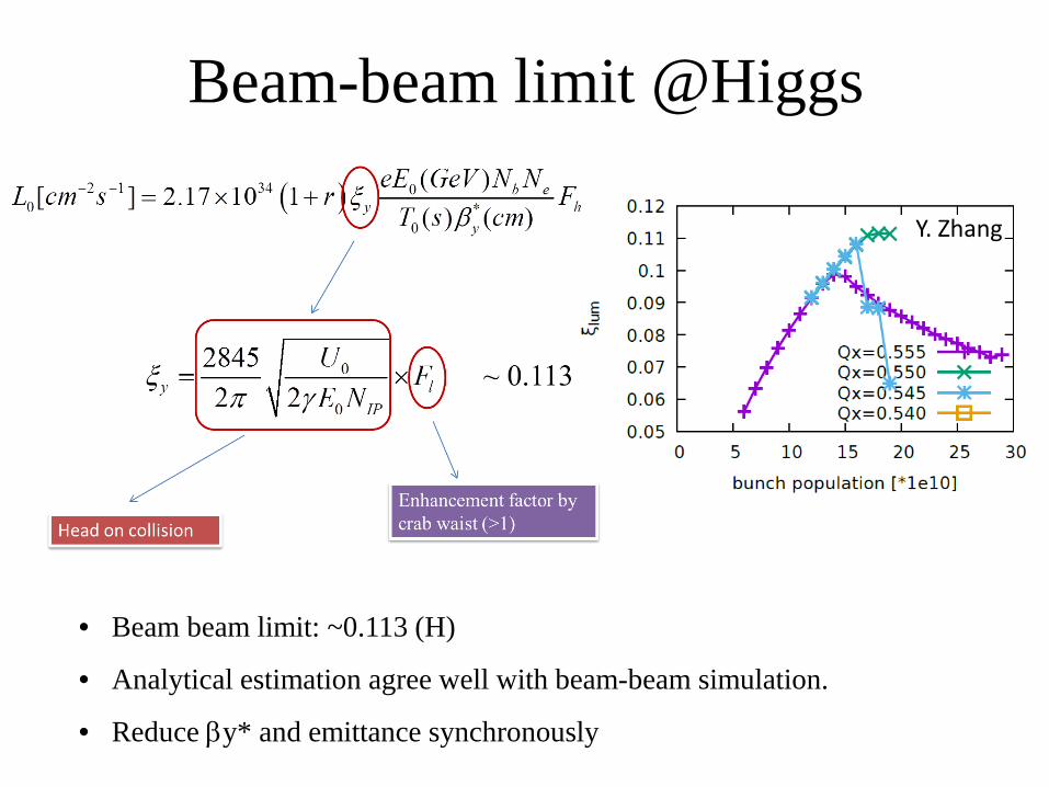
Beam-beam limit @Higgs
• Beam beam limit: ~0.113 (H)
• Analytical estimation agree well with beam-beam simulation.
• Reduce βy* and emittance synchronously
Y. Zhang
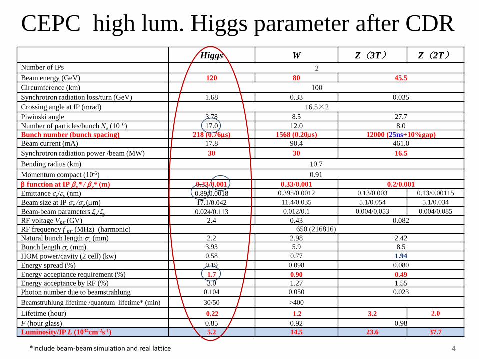
Higgs W Z(3T) Z(2T)Number of IPs 2Beam energy (GeV) 120 80 45.5Circumference (km) 100Synchrotron radiation loss/turn (GeV) 1.68 0.33 0.035Crossing angle at IP (mrad) 16.5×2Piwinski angle 3.78 8.5 27.7Number of particles/bunch Ne (1010) 17.0 12.0 8.0Bunch number (bunch spacing) 218 (0.76µs) 1568 (0.20µs) 12000 (25ns+10%gap)Beam current (mA) 17.8 90.4 461.0Synchrotron radiation power /beam (MW) 30 30 16.5Bending radius (km) 10.7Momentum compact (10-5) 0.91β function at IP βx* / βy* (m) 0.33/0.001 0.33/0.001 0.2/0.001Emittance εx/εy (nm) 0.89/0.0018 0.395/0.0012 0.13/0.003 0.13/0.00115Beam size at IP σx /σy (µm) 17.1/0.042 11.4/0.035 5.1/0.054 5.1/0.034Beam-beam parameters ξx/ξy 0.024/0.113 0.012/0.1 0.004/0.053 0.004/0.085RF voltage VRF (GV) 2.4 0.43 0.082RF frequency f RF (MHz) (harmonic) 650 (216816)Natural bunch length σz (mm) 2.2 2.98 2.42Bunch length σz (mm) 3.93 5.9 8.5HOM power/cavity (2 cell) (kw) 0.58 0.77 1.94Energy spread (%) 0.19 0.098 0.080Energy acceptance requirement (%) 1.7 0.90 0.49Energy acceptance by RF (%) 3.0 1.27 1.55Photon number due to beamstrahlung 0.104 0.050 0.023Beamstruhlung lifetime /quantum lifetime* (min) 30/50 >400Lifetime (hour) 0.22 1.2 3.2 2.0F (hour glass) 0.85 0.92 0.98Luminosity/IP L (1034cm-2s-1) 5.2 14.5 23.6 37.7
CEPC high lum. Higgs parameter after CDR
4*include beam-beam simulation and real lattice

𝟏𝟏𝟏𝟏𝝈𝝈𝒙𝒙 × 𝟐𝟐𝟐𝟐𝝈𝝈𝒚𝒚 × 𝟏𝟏.𝟏𝟏𝟓Strong limitation @ NP=11E10
DA optimization for the βy* =1mm @ Higgs
• Good for the injected beam
• Worse for the circulating
beam
We have strong requirement to understandfluctuation, beamstruhlung and beam-beamduring the simulations.
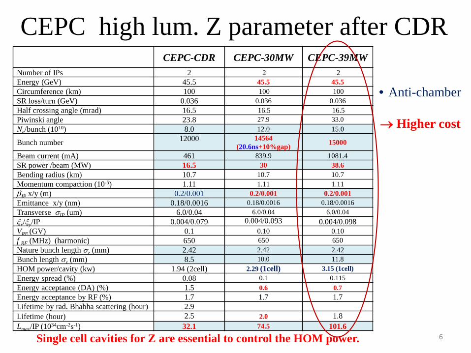
CEPC high lum. Z parameter after CDR
6
CEPC-CDR CEPC-30MW CEPC-39MWNumber of IPs 2 2 2Energy (GeV) 45.5 45.5 45.5Circumference (km) 100 100 100SR loss/turn (GeV) 0.036 0.036 0.036Half crossing angle (mrad) 16.5 16.5 16.5Piwinski angle 23.8 27.9 33.0Ne/bunch (1010) 8.0 12.0 15.0
Bunch number 12000 14564(20.6ns+10%gap) 15000
Beam current (mA) 461 839.9 1081.4SR power /beam (MW) 16.5 30 38.6Bending radius (km) 10.7 10.7 10.7Momentum compaction (10-5) 1.11 1.11 1.11βIP x/y (m) 0.2/0.001 0.2/0.001 0.2/0.001Emittance x/y (nm) 0.18/0.0016 0.18/0.0016 0.18/0.0016 Transverse σIP (um) 6.0/0.04 6.0/0.04 6.0/0.04ξx/ξy/IP 0.004/0.079 0.004/0.093 0.004/0.098VRF (GV) 0.1 0.10 0.10f RF (MHz) (harmonic) 650 650 650Nature bunch length σz (mm) 2.42 2.42 2.42Bunch length σz (mm) 8.5 10.0 11.8HOM power/cavity (kw) 1.94 (2cell) 2.29 (1cell) 3.15 (1cell)Energy spread (%) 0.08 0.1 0.115Energy acceptance (DA) (%) 1.5 0.6 0.7Energy acceptance by RF (%) 1.7 1.7 1.7Lifetime by rad. Bhabha scattering (hour) 2.9Lifetime (hour) 2.5 2.0 1.8Lmax/IP (1034cm-2s-1) 32.1 74.5 101.6
Single cell cavities for Z are essential to control the HOM power.
• Anti-chamber
→ Higher cost
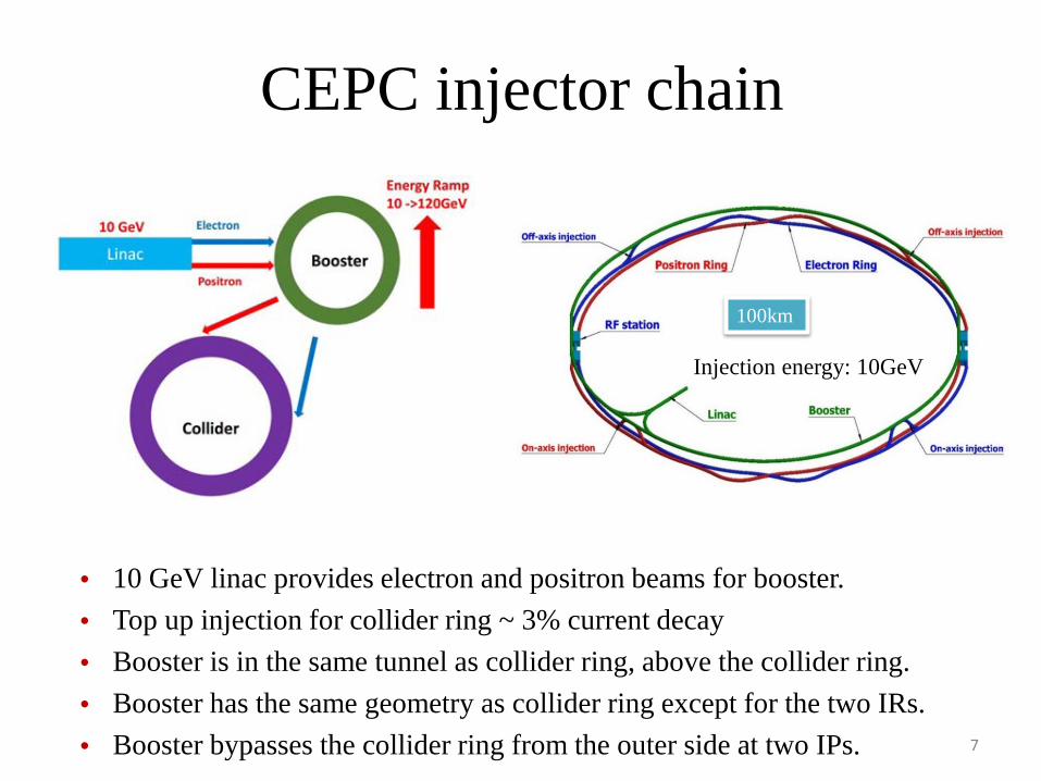
CEPC injector chain
• 10 GeV linac provides electron and positron beams for booster. • Top up injection for collider ring ~ 3% current decay• Booster is in the same tunnel as collider ring, above the collider ring.• Booster has the same geometry as collider ring except for the two IRs.• Booster bypasses the collider ring from the outer side at two IPs.
Injection energy: 10GeV
100km
7

Booster parameters (CDR)
8
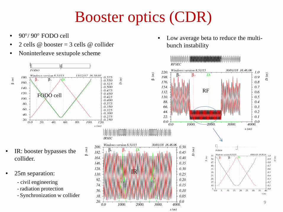
Booster optics (CDR)
FODO cell
• 90°/ 90° FODO cell• 2 cells @ booster = 3 cells @ collider• Noninterleave sextupole scheme
9
RF
• Low average beta to reduce the multi-bunch instability
IR
• IR: booster bypasses the collider.
• 25m separation: - civil engineering- radiation protection- Synchronization w collider
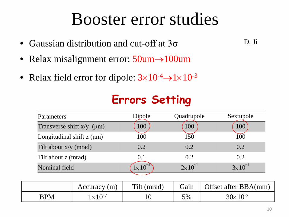
Booster error studies• Gaussian distribution and cut-off at 3σ
Errors Setting
Accuracy (m) Tilt (mrad) Gain Offset after BBA(mm)BPM 1×10⁻⁷ 10 5% 30×10-3
Parameters Dipole Quadrupole SextupoleTransverse shift x/y (μm) 100 100 100Longitudinal shift z (μm) 100 150 100Tilt about x/y (mrad) 0.2 0.2 0.2Tilt about z (mrad) 0.1 0.2 0.2Nominal field 1×10⁻³ 2×10⁻⁴ 3×10⁻⁴
10
D. Ji
• Relax misalignment error: 50um→100um
• Relax field error for dipole: 3×10⁻⁴→1×10⁻³
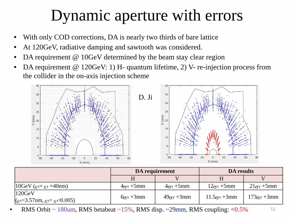
Dynamic aperture with errors
DA requirement DA resultsH V H V
10GeV (εx= εy =40nm) 4σx +5mm 4σy +5mm 12σx +5mm 21σy +5mm120GeV(εx=3.57nm, εy= εx*0.005) 6σx +3mm 49σy +3mm 11.5σx +3mm 173σy +3mm
• With only COD corrections, DA is nearly two thirds of bare lattice• At 120GeV, radiative damping and sawtooth was considered.• DA requirement @ 10GeV determined by the beam stay clear region• DA requirement @ 120GeV: 1) H- quantum lifetime, 2) V- re-injection process from
the collider in the on-axis injection scheme
11• RMS Orbit ~ 180um, RMS betabeat ~15%, RMS disp. ~29mm, RMS coupling: <0.5%
D. Ji
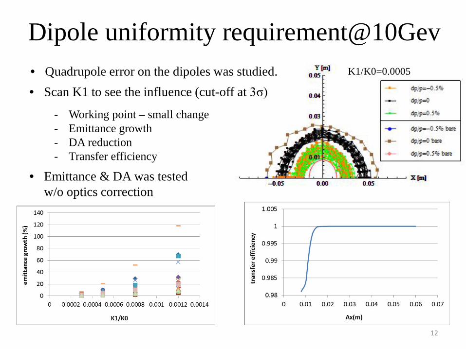
Dipole uniformity requirement@10Gev
12
K1/K0=0.0005• Quadrupole error on the dipoles was studied.• Scan K1 to see the influence (cut-off at 3σ)
- Working point – small change- Emittance growth- DA reduction- Transfer efficiency
• Emittance & DA was tested w/o optics correction
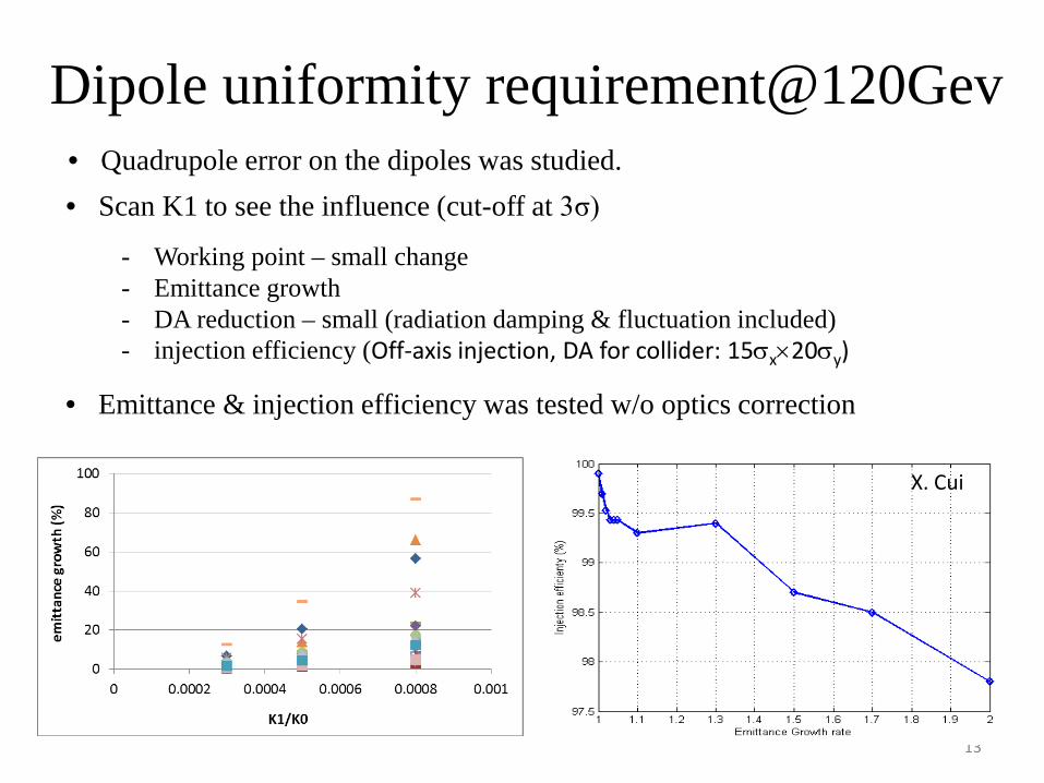
Dipole uniformity requirement@120Gev
13
• Quadrupole error on the dipoles was studied.• Scan K1 to see the influence (cut-off at 3σ)
- Working point – small change- Emittance growth- DA reduction – small (radiation damping & fluctuation included)- injection efficiency (Off-axis injection, DA for collider: 15σx×20σy)
• Emittance & injection efficiency was tested w/o optics correction
X. Cui

Multipole errors @ booster
• Reference radius: 27.5mm
14
dipole quadrupole sextupole
B1/B0 ≤ 3×10⁻⁴
B2/B0 ≤ 2×10⁻⁴ B2/B1 ≤ 4×10⁻⁴
B3/B0 ≤ 2×10⁻⁵ B3/B1 ≤ 1×10⁻⁴ B3/B2≤ 1×10⁻³
B4/B0 ≤ 8×10⁻⁵ B4/B1 ≤ 1×10⁻⁴ B4/B2 ≤ 3×10⁻⁴
B5/B0 ≤ 2×10⁻⁵ B5/B1 ≤ 1×10⁻⁴ B5/B2 ≤ 1×10⁻³
B6/B0 ≤ 8×10⁻⁵ B6/B1 ≤ 5×10⁻⁵ B6/B2 ≤ 3×10⁻⁴
B7/B0 ≤ 2×10⁻⁵ B7/B1 ≤ 5×10⁻⁵ B7/B2 ≤ 1×10⁻³
B8/B0 ≤ 8×10⁻⁵ B8/B1 ≤ 5×10⁻⁵ B8/B2 ≤ 3×10⁻⁴
B9/B0 ≤ 2×10⁻⁵ B9/B1 ≤ 5×10⁻⁵ B9/B2 ≤ 1×10⁻³
B10/B0 ≤ 8×10⁻⁵ B10/B1 ≤ 5×10⁻⁵ B10/B2 ≤ 3×10⁻⁴
• 10GeV
• w/o optics correction

Dipole reproducibility requirement@10Gev• Increase/decrease the strength of all the dipoles by the same amount.• Decrease/increase the strength of quadrupoles & sextupoles → energy mismatch• Evaluate the influence: working point, closed orbit, DA, energy acceptance • Working point should not pass through the lower order resonance • No shrink for dynamic aperture• Reproducibility requirement for dipoles: ~0.02%• Stability requirement for power supply: ~0.01%
original +0.01% -0.01% +0.05% -0.05%
nux 263.18 263.12 263.25 262.84 263.52
nuy 261.28 261.21 261.34 260.94 261.61
∆x (um) 0 -54 54 -270 270
DA (%) 100 100 100 90 90
15
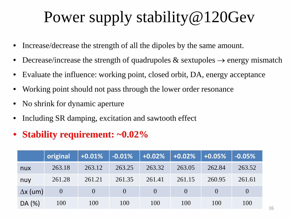
Power supply stability@120Gev• Increase/decrease the strength of all the dipoles by the same amount.
• Decrease/increase the strength of quadrupoles & sextupoles → energy mismatch
• Evaluate the influence: working point, closed orbit, DA, energy acceptance
• Working point should not pass through the lower order resonance
• No shrink for dynamic aperture
• Including SR damping, excitation and sawtooth effect
• Stability requirement: ~0.02%
16
original +0.01% -0.01% +0.02% +0.02% +0.05% -0.05%
nux 263.18 263.12 263.25 263.32 263.05 262.84 263.52
nuy 261.28 261.21 261.35 261.41 261.15 260.95 261.61
∆x (um) 0 0 0 0 0 0 0
DA (%) 100 100 100 100 100 100 100

Effect of earthfield @10GeV• ~20% vacuum pipe (drift) is exposed in earthfield directly.• treat drifts as week dipole to simulate the effect of earthfield• Assume earthfield: 0.3~0.6 gauss (simple model: perpendicular component only )• Working point can be corrected by weaken the dipoles systematically (-0.07%)• Global COD correction was tested for 0.3 gauss earthfield.• DA is acceptable after COD correction.
0.3 gauss
17
D. Ji
first turn trajectory
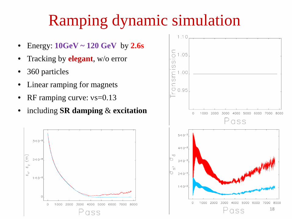
Ramping dynamic simulation• Energy: 10GeV ~ 120 GeV by 2.6s• Tracking by elegant, w/o error• 360 particles• Linear ramping for magnets• RF ramping curve: νs=0.13• including SR damping & excitation
18
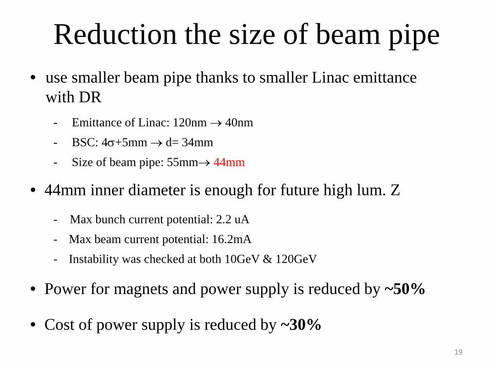
Reduction the size of beam pipe• use smaller beam pipe thanks to smaller Linac emittance
with DR- Emittance of Linac: 120nm → 40nm- BSC: 4σ+5mm → d= 34mm- Size of beam pipe: 55mm→ 44mm
• 44mm inner diameter is enough for future high lum. Z
- Max bunch current potential: 2.2 uA- Max beam current potential: 16.2mA- Instability was checked at both 10GeV & 120GeV
• Power for magnets and power supply is reduced by ~50%
• Cost of power supply is reduced by ~30%19
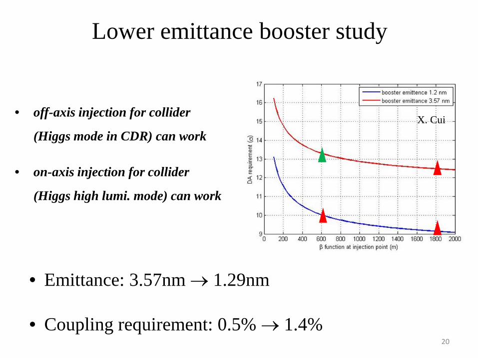
Lower emittance booster study
• off-axis injection for collider
(Higgs mode in CDR) can work
• on-axis injection for collider
(Higgs high lumi. mode) can work
• Emittance: 3.57nm → 1.29nm
• Coupling requirement: 0.5% → 1.4% 20
X. Cui
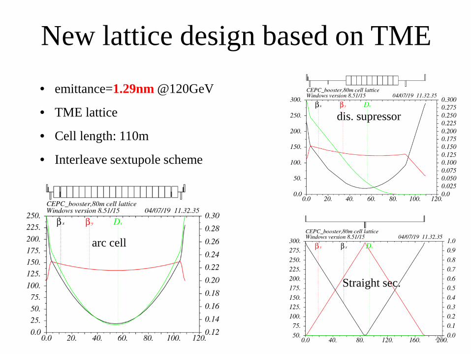
New lattice design based on TME
• emittance=1.29nm @120GeV
• TME lattice
• Cell length: 110m
• Interleave sextupole scheme
dis. supressor
arc cell
Straight sec.
21
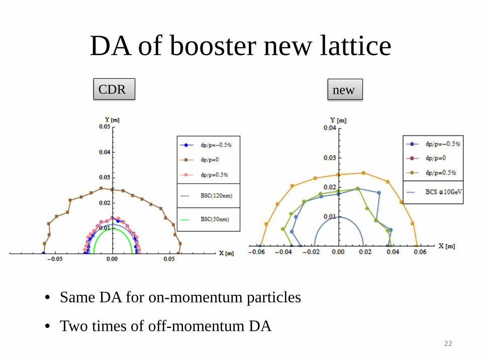
DA of booster new latticeCDR new
22
• Same DA for on-momentum particles
• Two times of off-momentum DA
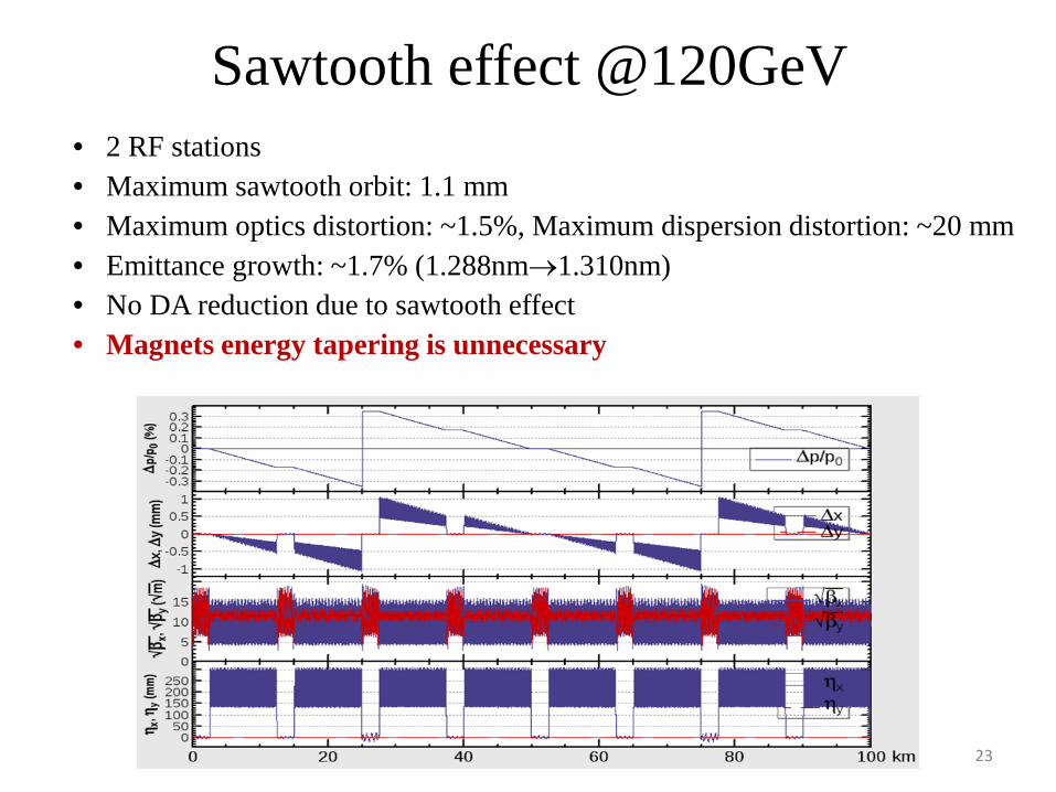
Sawtooth effect @120GeV
23
• 2 RF stations• Maximum sawtooth orbit: 1.1 mm• Maximum optics distortion: ~1.5%, Maximum dispersion distortion: ~20 mm• Emittance growth: ~1.7% (1.288nm→1.310nm)• No DA reduction due to sawtooth effect• Magnets energy tapering is unnecessary

DA requirement DA resultsH V H V
10GeV (εx= εy =40nm) 4σx +5mm 4σy +5mm 14σx +5mm 18σy +5mm120GeV (εx=1.29nm, εy= εx*0.014) 6σx +3mm 13σy +3mm 9.4σx +3mm 22σy +3mm
Dynamic aperture w/o errors
120GeV 120GeV
24
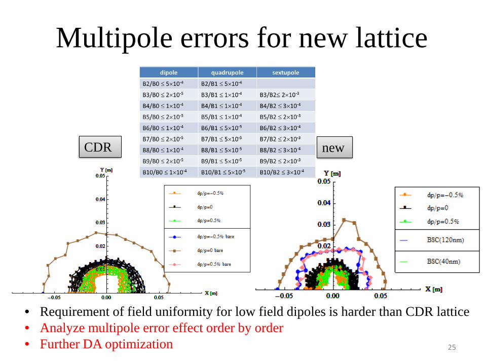
Multipole errors for new lattice
• Requirement of field uniformity for low field dipoles is harder than CDR lattice• Analyze multipole error effect order by order• Further DA optimization
CDR new
25
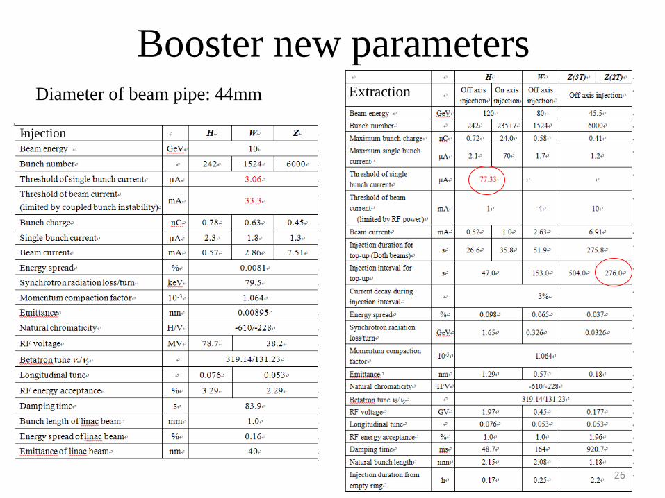
Booster new parameters
Injection
Extraction
26
Diameter of beam pipe: 44mm

Geometry design of new lattice
• Exact match for three rings-- error=±0.17m 27

Multi-bunch instability
28
• Feedback system is essential @10 GeV.- Damping time: 90s- Growth time (T): 3.1ms- Growth time (L): 6.3ms
• tap number always more than 2.
• Quick feedback + large ring → low order filter
J. Yue, Y Sui et al.

Transverse feedback status
GeEh
f kmrf
FB
⋅⋅⋅
=/2ββ
τ1
K
FB
RVP
2
21 ∆⋅=
E=10GeV,βm=βk=120m,Δx=0.3mm, τFB
=1.45 ms,so ΔVFB⊥=9.27kV, P=344w.
• 4-tap filter was considered
• One BPM and One kicker, 90 degree phase shift and DC rejection both are got in FPGA.
• 2 amplifiers, 300W for each
J. Yue, Y Sui et al.
29
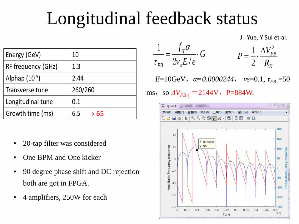
Longitudinal feedback status
→ 65
GeE
f
s
rf
FB
⋅=/να
τ 2
1
K
FB
RVP
2
21 ∆⋅=
E=10GeV,α=0.0000244, νs=0.1, τFB =50
ms,so ΔVFB|| =2144V,P=884W.
• 20-tap filter was considered
• One BPM and One kicker
• 90 degree phase shift and DC rejection both are got in FPGA.
• 4 amplifiers, 250W for each
30
J. Yue, Y Sui et al.
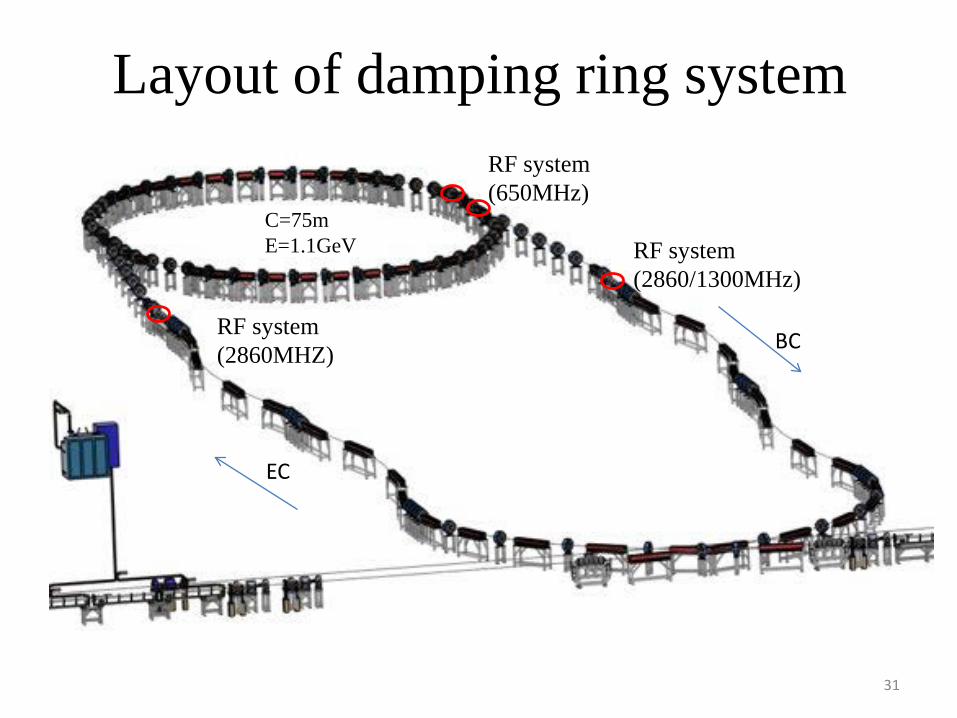
RF system(2860/1300MHz)
RF system(2860MHZ)
Layout of damping ring systemRF system(650MHz)
EC
BC
31
C=75mE=1.1GeV

DR parameters
DR V2.0 Energy (Gev) 1.1 Circumference (m) 75.4 Bending radius (m) 3.6 Dipole strength B0 (T) 1.03 U0 (kev/turn) 36.3 Damping time x/y/z (ms) 15.2/15.2/7.6 δ0 (%) 0.05 ε0 (mm.mrad) 376.7 injection σz (mm) 5 Extract σz (mm) 7.5 εinj (mm.mrad) 2500 εext x/y (mm.mrad) 530/180 δinj /δext (%) 0.18 /0.05 Energy acceptance by RF(%) 1.0 fRF (MHz) 650 VRF (MV) 2.0
• Linac repetition: 100Hz
• two-bunch storage scheme
• Storage time: 20 ms
• Emittance (norm.): 2500→ 530 mm.mrad
• Large trans. acceptance→ inj. efficiency
32
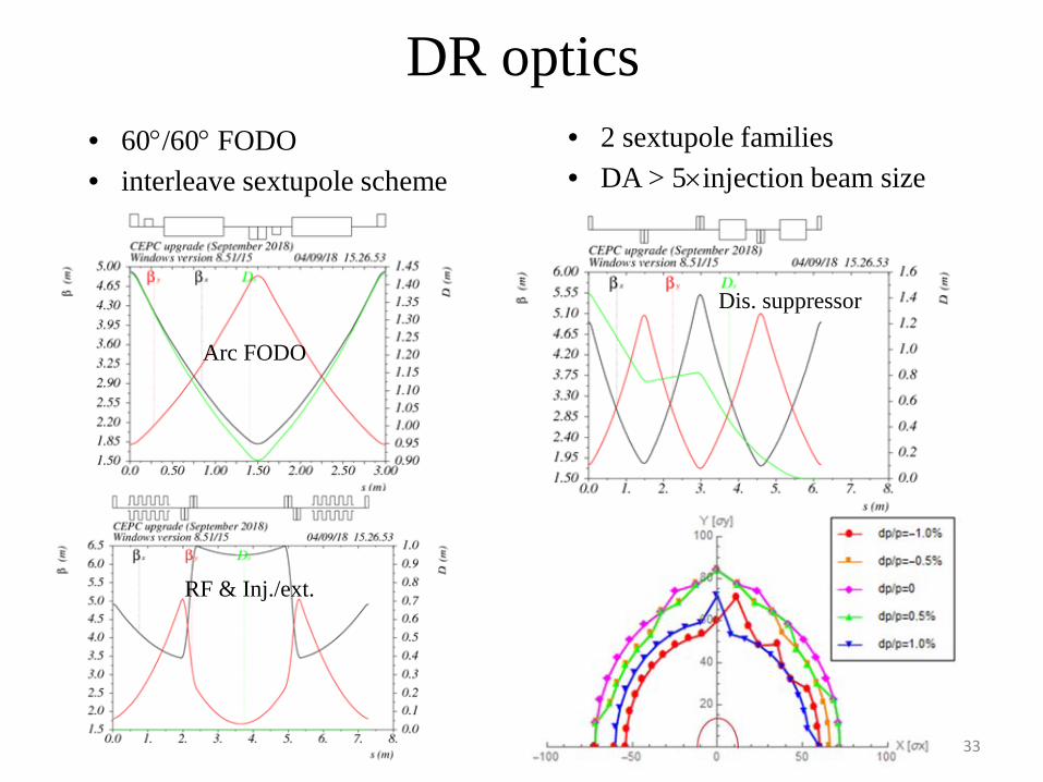
DR optics• 60°/60° FODO• interleave sextupole scheme
• 2 sextupole families• DA > 5×injection beam size
Arc FODO
Dis. suppressor
RF & Inj./ext.
33
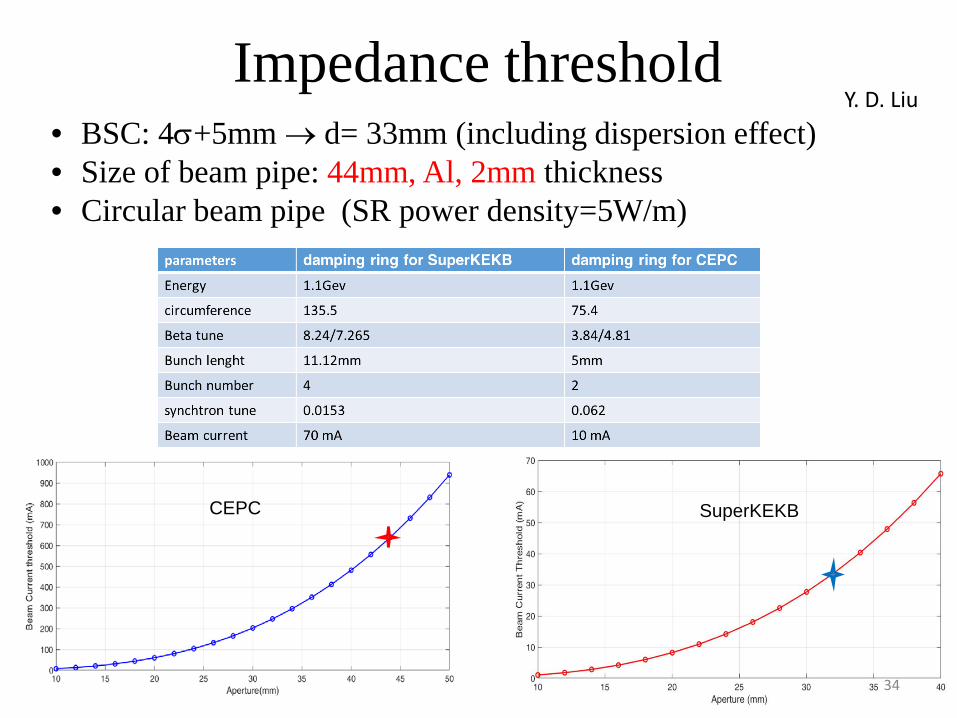
Impedance threshold• BSC: 4σ+5mm → d= 33mm (including dispersion effect)• Size of beam pipe: 44mm, Al, 2mm thickness• Circular beam pipe (SR power density=5W/m)
SuperKEKBCEPC
Y. D. Liu
34

CSR threshold• The beam is assumed to be moving in a circle of radius ρ
between two parallel plates at locations y=±h
• The threshold of bunch population for CSR is given by
• For CEPC DR, σzρ1/2/h3/2=4.4 (=> CSR shielded)
• The CSR threshold in CEPC DR is Nb,Th = 1.46×10¹¹ >> Nb = 9.36×10⁹.
- Inner diameter of beam pipe: 44 mm
35

IBS effect• Equilibrium emittance (H/V): 359/18 mm⋅mrad• No emittance growth at design bunch current (1.5nC/bunch)• IBS threshold: ~100nC/bunch• IBS is not a concern in CEPC DR.
S. K. Tian
36

EC/BC parametersEC
E0 (Gev) 1.1
δ0 (%) 0.6
σz0 (mm) 1.5
fRF (MHz) 2860
VRF (MV) 22.0Length of acc. Structure (m) 0.82
φRF (degree) 89.7
R56 (m) -0.833
Ef (Gev) 1.1
δf (%) 0.18
σzf (mm) 5
BC
E0 (Gev) 1.1
δ0 (%) 0.05
σz0 (mm) 7.5
fRF (MHz) 2860/1300
VRF (MV) 13.1/29Length of acc. Structure (m) 0.48/2.5
φRF (degree) 89.6
R56 (m) -1.4
Ef (Gev) 1.1
δf (%) 0.54
σzf (mm) 0.7
37
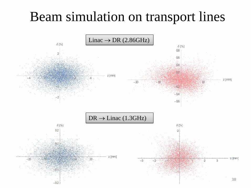
Beam simulation on transport lines
4 2 2 4z mm
2
1
1
2
20 10 10z mm
0.6
0.4
0.2
0.2
0.4
0.6
0.8
Linac → DR (2.86GHz)
DR → Linac (1.3GHz)
38

Emittance evolution on transport lines
39
• Dipole strength for the chicane: 0.49T• No error included• No emittance growth due to radiation effect
Linac → DR DR → Linac
X. H. Cui
Summary
• Booster design in CDR was refined. Become more solid.
• A lot of effort to find a new design for booster with lower emittance
- Higgs off-axis injection in CDR- Higgs on-axis injection in high lumi. mode
• No principle difficulties to use the new booster. Still comprehensive assessment of error effect is necessary.
• DR system was specified. Key beam parameters can be realized. Error studies on the way.
• Both transverse and longitudinal feedback system has substantive progress.
• Propose new parameters with higher luminosity after CDR.

Thanks for your attention!
Back up
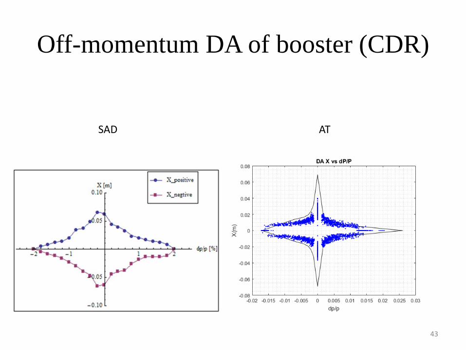
Off-momentum DA of booster (CDR)
43
SAD AT


![Gilbert damping in binary magnetic multilayers · E. BARATI AND M. CINAL PHYSICAL REVIEW B 95, 134440 (2017) ons-d exchangeattheinterfaces,hasbeenproposedbyBerger [53]. More recently,](https://static.fdocument.org/doc/165x107/5d4e675988c99303708b99e1/gilbert-damping-in-binary-magnetic-multilayers-e-barati-and-m-cinal-physical.jpg)