INSTALLATION MANUAL - Daikin€¦ · • For installation of the outdoor unit, refer to the...
21
English Deutsch Français Español Italiano Nederlands Portugues Русский Ελληνικά MODELS (Ceiling Suspended type) FHQ35CAVEB FHQ100CAVEB FHQ50CAVEB FHQ125CAVEB FHQ60CAVEB FHQ140CAVEB FHQ71CAVEB FHQ140CAVEA SPLIT SYSTEM Air Conditioners INSTALLATION MANUAL CAREFULLY READ THESE INSTRUCTIONS BEFORE INSTALLATION. KEEP THIS MANUAL IN A HANDY PLACE FOR FUTURE REFERENCE. LESEN SIE DIESE HINWEISE VOR DER INSTALLATION SORGFÄLTIG DURCH. BEWAHREN SIE DIESE ANLEITUNG AN EINEM LEICHT ZUGÄNGLICHEN ORT FÜR SPÄTERES NACHSCHLAGEN AUF. VEUILLEZ LIRE ATTENTIVEMENT CES INSTRUCTIONS AVANT L'INSTALLATION. CONSERVEZ CE MANUEL EN LIEU SÛR POUR POUVOIR VOUS Y REPORTER ULTÉRI- EUREMENT. LEA DETENIDAMENTE ESTAS INSTRUCCIONES ANTES DE LA INSTALACIÓN CONSERVE ESTE MANUAL PARA POSIBLES CONSULTAS FUTURAS. PRIMA DELL'INSTALLAZIONE, LEGGERE ATTENTAMENTE LE PRESENTI ISTRUZIONI. CONSERVARE IL PRESENTE MANUALE IN UN LUOGO FACILMENTE ACCESSIBILE PER RIFERIMENTO FUTURO. ΔΙΑΒΑΣΤΕ ΠΡΟΣΕΚΤΙΚΑ ΑΥΤΕΣ ΤΙΣ ΟΔΗΓΙΕΣ ΠΡΙΝ ΤΗΝ ΕΓΚΑΤΑΣΤΑΣΗ ΦΥΛΑΞΤΕ ΑΥΤΟ ΤΟ ΕΓΧΕΙΡΙΔΙΟ ΣΕ ΒΟΛΙΚΟ ΜΕΡΟΣ ΓΙΑ ΜΕΛΛΟΝΤΙΚΗ ΑΝΑΦΟΡΑ. LEES DEZE INSTRUCTIES ZOGVULDIG DOOR VOORDAT MET DE INSTALLATIE WORDT BEGONNEN. BEWAAR DEZE HANDLEIDING VOOR TOEKOMSTIG GEBRUIK OP EEN GESCHIKTE PLAATS ONDER HANDBEREIK. LEIA ATENTAMENTE ESTAS INSTRUÇÕES ANTES DA INSTALAÇÃO. MANTENHA ESTE MANUAL NUM LOCAL DE FÁCIL ACESSO PARA CONSULTA. ПЕРЕД УСТАНОВКОЙ ВНИМАТЕЛЬНО ПРОЧИТАЙТЕ ДАННЫЕ ИНСТРУКЦИИ. ХРАНИТЕ ДАННОЕ РУКОВОДСТВО В ЛЕГКО ДОСТУПНОМ МЕСТЕ ДЛЯ ЕГО ПОСЛЕДУЮЩЕГО ИСПОЛЬЗОВАНИЯ. MONTAJDAN ÖNCE BU YÖNERGELERİ DİKKATLİCE OKUYUN DAHA SONRA BAKMAK ÜZERE BU KILAVUZU SAKLAYIN
Transcript of INSTALLATION MANUAL - Daikin€¦ · • For installation of the outdoor unit, refer to the...
English
Deutsch
Français
Español
Italiano
Nederlands
Portugues
Русский
Ελληνικά
MODELS
(Ceiling Suspended type)
FHQ35CAVEB FHQ100CAVEB
FHQ50CAVEB FHQ125CAVEB
FHQ60CAVEB FHQ140CAVEB
FHQ71CAVEB FHQ140CAVEA
SPLIT SYSTEM Air Conditioners
INSTALLATION MANUAL
CAREFULLY READ THESE INSTRUCTIONS BEFORE INSTALLATION.KEEP THIS MANUAL IN A HANDY PLACE FOR FUTURE REFERENCE.
LESEN SIE DIESE HINWEISE VOR DER INSTALLATION SORGFÄLTIG DURCH.BEWAHREN SIE DIESE ANLEITUNG AN EINEM LEICHT ZUGÄNGLICHEN ORT FÜR SPÄTERES NACHSCHLAGEN AUF.
VEUILLEZ LIRE ATTENTIVEMENT CES INSTRUCTIONS AVANT L'INSTALLATION.CONSERVEZ CE MANUEL EN LIEU SÛR POUR POUVOIR VOUS Y REPORTER ULTÉRI-EUREMENT.
LEA DETENIDAMENTE ESTAS INSTRUCCIONES ANTES DE LA INSTALACIÓNCONSERVE ESTE MANUAL PARA POSIBLES CONSULTAS FUTURAS.
PRIMA DELL'INSTALLAZIONE, LEGGERE ATTENTAMENTE LE PRESENTI ISTRUZIONI.CONSERVARE IL PRESENTE MANUALE IN UN LUOGO FACILMENTE ACCESSIBILE PER RIFERIMENTO FUTURO.
ΔΙΑΒΑΣΤΕ ΠΡΟΣΕΚΤΙΚΑ ΑΥΤΕΣ ΤΙΣ ΟΔΗΓΙΕΣ ΠΡΙΝ ΤΗΝ ΕΓΚΑΤΑΣΤΑΣΗΦΥΛΑΞΤΕ ΑΥΤΟ ΤΟ ΕΓΧΕΙΡΙΔΙΟ ΣΕ ΒΟΛΙΚΟ ΜΕΡΟΣ ΓΙΑ ΜΕΛΛΟΝΤΙΚΗ ΑΝΑΦΟΡΑ.
LEES DEZE INSTRUCTIES ZOGVULDIG DOOR VOORDAT MET DE INSTALLATIE WORDT BEGONNEN.BEWAAR DEZE HANDLEIDING VOOR TOEKOMSTIG GEBRUIK OP EEN GESCHIKTE PLAATS ONDER HANDBEREIK.
LEIA ATENTAMENTE ESTAS INSTRUÇÕES ANTES DA INSTALAÇÃO.MANTENHA ESTE MANUAL NUM LOCAL DE FÁCIL ACESSO PARA CONSULTA.
ПЕРЕД УСТАНОВКОЙ ВНИМАТЕЛЬНО ПРОЧИТАЙТЕ ДАННЫЕ ИНСТРУКЦИИ.ХРАНИТЕ ДАННОЕ РУКОВОДСТВО В ЛЕГКО ДОСТУПНОМ МЕСТЕ ДЛЯ ЕГО ПОСЛЕДУЮЩЕГО ИСПОЛЬЗОВАНИЯ.
MONTAJDAN ÖNCE BU YÖNERGELERİ DİKKATLİCE OKUYUNDAHA SONRA BAKMAK ÜZERE BU KILAVUZU SAKLAYIN
00_CV_3P368557-1.fm Page 1 Wednesday, November 26, 2014 5:21 PM
1 English
FHQ35CAVEBFHQ50CAVEBFHQ60CAVEBFHQ71CAVEB
FHQ100CAVEBFHQ125CAVEBFHQ140CAVEBFHQ140CAVEA
SPLIT SYSTEM Air Conditioners Installation manual
CONTENTS
1. SAFETY PRECAUTIONS ................................................1
2. BEFORE INSTALLATION.................................................2
3. SELECTION OF INSTALLATION LOCATION..................3
4. PREPARATION BEFORE INSTALLATION.......................4
5. INSTALLATION OF THE INDOOR UNIT .........................5
6. REFRIGERANT PIPING WORK......................................6
7. DRAIN PIPING WORK.....................................................9
8. ELECTRIC WIRING WORK...........................................10
9. HOW TO CONNECT WIRINGS AND
WIRING EXAMPLE........................................................11
10. MOUNTING SUCTION GRILLE ·
DECORATION SIDE PANEL..........................................14
11. FIELD SETTING ............................................................14
12. TEST OPERATION ........................................................16
13. WIRING DIAGRAM ........................................................18
The original instructions are written in English. All other lan-
guages are translations of the original instructions.
1. SAFETY PRECAUTIONS
Be sure to follow this “SAFETY PRECAUTIONS”.
This product comes under the term “appliances not accessible
to the general public”.
• This manual classifies the precautions into WARNINGS and
CAUTIONS.
Be sure to follow all the precautions below: They are all
important for ensuring safety.
WARNING .................... Indicates a potentially hazard-
ous situation which, if not
avoided, could result in death
or serious injury.
CAUTION ..................... Indicates a potentially hazard-
ous situation which, if not
avoided, may result in minor or
moderate injury.
It may also be used to alert
against unsafe practices.
• After the installation is completed, test the air conditioner and
check if the air conditioner operates properly. Give the user
adequate instructions concerning the use and cleaning of the
indoor unit according to the Operation Manual. Ask the user
to keep this manual and the Operation Manual together in a
handy place for future reference.
WARNING
• Ask your local dealer or qualified personnel to carry out
installation work.
Improper installation may result in water leakage, electric
shocks or a fire.
• Perform installation work in accordance with this installation
manual.
Improper installation may result in water leakage, electric
shocks or a fire.
• Consult your dealer regarding what to do in case of refriger-
ant leakage.
When the air conditioner is installed in a small room, it is nec-
essary to take proper measures so that the amount of any
leaked refrigerant does not exceed the concentration limit in
the event of a leakage.
Otherwise, this may lead to an accident due to oxygen defi-
ciency.
• Be sure to use only the specified parts and accessories for
installation work.
Failure to use the specified parts may result in the air condi-
tioner falling down, water leakage, electric shocks, a fire, etc.
• Install the air conditioner on a foundation that can withstand
its mass.
Insufficient strength may result in the air conditioner falling
down and causing injury.
In addition, it may lead to vibration of indoor units and cause
unpleasant chattering noise.
• Carry out the specified installation work in consideration of
strong winds, typhoons, or earthquakes.
Improper installation may result in an accident such as air
conditioner falling.
• Make certain that all electrical work is carried out by qualified
personnel according to the applicable legislation (note 1) and
this installation manual, using a separate circuit.
In addition, even if the wiring is short, make sure to use a wir-
ing that has sufficient length and never connect additional
wiring to make the length sufficient.
Insufficient capacity of the power supply circuit or improper
electrical construction may lead to electric shocks or a fire.
(note 1) applicable legislation means “All international,
national and local directives, laws, regulations and/
or codes which are relevant and applicable for a
certain product or domain”.
• Earth the air conditioner.
Do not connect the earth wiring to gas or water piping, light-
ning conductor or telephone earth wiring.
Incomplete earthing may cause electric shocks or a fire.
• Be sure to install an earth leakage breaker.
Failure to do so may cause electric shocks and a fire.
• Disconnect the power supply before touching the electric
components.
If you touch the live part, you may get an electric shocks.
• Make sure that all wiring is secure, using the specified wir-
ings and ensuring that external forces do not act on the ter-
minal connections or wirings.
Incomplete connection or fixing may cause an overheat or a
fire.
• When wiring between the indoor and outdoor units, and wir-
ing the power supply, form the wirings orderly so that the con-
trol box lid can be securely fastened.
If the control box lid is not in place, overheat of the terminals,
electric shocks or a fire may be caused.
• If refrigerant gas leaks during installation work, ventilate the
area immediately.
Toxic gas may be produced if refrigerant gas comes into con-
tact with a fire.
• After completing the installation work, check to make sure
that there is no leakage of refrigerant gas.
Toxic gas may be produced if refrigerant gas leaks into the
room and comes into contact with a source of a fire, such as
a fan heater, stove or cooker.
• Never directly touch any accidental leaking refrigerant. This
could result in severe wounds caused by frostbite.
01_EN_3P368557-1.fm Page 1 Wednesday, December 10, 2014 10:31 AM
English 2
CAUTION
• Install drain piping according to this installation manual to
ensure good drainage, and insulate the piping to prevent
condensation.
Improper drain piping may cause water leakage, make the
furniture get wet.
• Install the air conditioner, power supply wiring, remote con-
troller wiring and transmission wiring at least 1 meter away
from televisions or radios to prevent image interference or
noise.
(Depending on the radio waves, a distance of 1 meter may
not be sufficient to eliminate the noise.)
• Install the indoor unit as far as possible from fluorescent
lamps.
If a wireless remote controller kit is installed, the transmission
distance may be shorter in a room where an electronic light-
ing type (inverter or rapid start type) fluorescent lamp is
installed.
• Do not install the air conditioner in places such as the follow-
ing:
1. Where there is mist of oil, oil spray or vapour for example
a kitchen.
Resin parts may deteriorate, and cause them to fall out or
water to leak.
2. Where corrosive gas, such as sulfurous acid gas, is pro-
duced.
Corrosion of copper pipings or brazed parts may cause
the refrigerant to leak.
3. Where there is machinery which emits electromagnetic
waves.
Electromagnetic waves may disturb the control system,
and cause malfunction of the equipment.
4. Where flammable gases may leak, where carbon fibre or
ignitable dust is suspended in the air or where volatile
flammables, such as thinner or gasoline, are handled.
If the gas should leak and remained around the air condi-
tioner, it may cause ignition.
• The air conditioner is not intended for use in a potentially
explosive atomosphere.
2. BEFORE INSTALLATION
When unpacking and moving the indoor unit after
unpacked, do not apply force to the piping (refrigerant and
drain) and resin parts.
• Make sure to check in advance that the refrigerant to be used
for installation work is R410A.
(The air conditioner will not properly operate if a wrong refrig-
erant is used.)
• For installation of the outdoor unit, refer to the installation
manual attached to the outdoor unit.
• Do not throw away the accessories until the installation work
is completed.
• After the indoor unit is carried into the room, to avoid the
indoor unit from getting damaged, take measures to protect
the indoor unit with packing materials.
(1) Determine the route to carry the unit into the room.
(2) Do not unpack the unit until it is carried to the installation
location.
Where unpacking is unavoidable, use a sling of soft
material or protective plates together with a rope when
lifting, to avoid damage or scratches to the indoor units.
• Have the customer actually operate the air conditioner while
looking at the manual.
Instruct the customer how to operate the air conditioner (par-
ticularly cleaning of the air filters, operation procedures, and
temperature adjustment).
• For selection of installation location, use the installation pat-
tern paper (used in common with the packing case.) as refer-
ence.
• Do not use the air conditioner where in the salty atmosphere
such as coastal areas, vehicles, vessels or the voltage fluc-
tuation is frequent such as factories.
• Take off static electricity from the body when carrying out wir-
ing and the control box lid is removed.
The electric parts may be damaged.
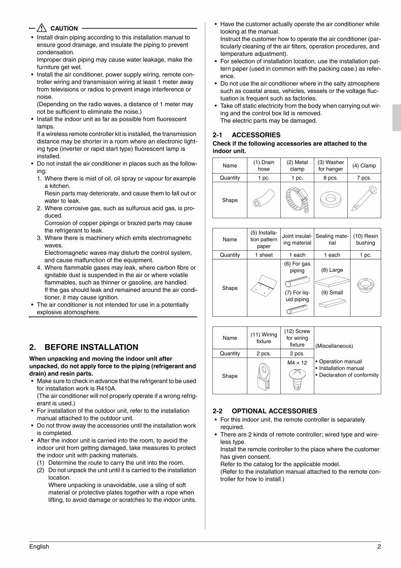
2-1 ACCESSORIES
Check if the following accessories are attached to the
indoor unit.
2-2 OPTIONAL ACCESSORIES
• For this indoor unit, the remote controller is separately
required.
• There are 2 kinds of remote controller; wired type and wire-
less type.
Install the remote controller to the place where the customer
has given consent.
Refer to the catalog for the applicable model.
(Refer to the installation manual attached to the remote con-
troller for how to install.)
Name(1) Drain
hose
(2) Metal
clamp
(3) Washer
for hanger(4) Clamp
Quantity 1 pc. 1 pc. 8 pcs. 7 pcs.
Shape
Name
(5) Installa-
tion pattern
paper
Joint insulat-
ing material
Sealing mate-
rial
(10) Resin
bushing
Quantity 1 sheet 1 each 1 each 1 pc.
Shape
(6) For gas
piping
(7) For liq-
uid piping
(8) Large
(9) Small
Name(11) Wiring
fixture
(12) Screw
for wiring
fixture (Miscellaneous)
• Operation manual
• Installation manual
• Declaration of conformity
Quantity 2 pcs. 2 pcs.
Shape
M4 × 12
01_EN_3P368557-1.fm Page 2 Wednesday, December 10, 2014 10:31 AM
3 English
CARRY OUT THE WORK GIVING CAUTION TO THE
FOLLOWING ITEMS AND AFTER THE WORK IS
COMPLETED CHECK THESE AGAIN.
1. Items to be checked after the installation work is com-
pleted
*Make sure to recheck the items of “SAFETY PRECAUTIONS”
2. Items to be checked at delivery
Points of the operation explanation
3. SELECTION OF INSTALLATION LOCA-
TION
When unpacking and moving the indoor unit after
unpacked, do not apply force to the piping (refrigerant and
drain) and resin parts.
(1) Select the installation location that meets the following
conditions and get approval of the customer.
• Where the cool and warm air spreads evenly in the room.
• Where there is no obstacles in the air passage.
• Where drainage can be ensured.
• Where the ceiling lower surface is not inclined.
• Where there is sufficient strength to withstand the mass
of the indoor unit (if the strength is insufficient, the indoor
unit may vibrate and get in contact with the ceiling and
generate unpleasant chattering noise).
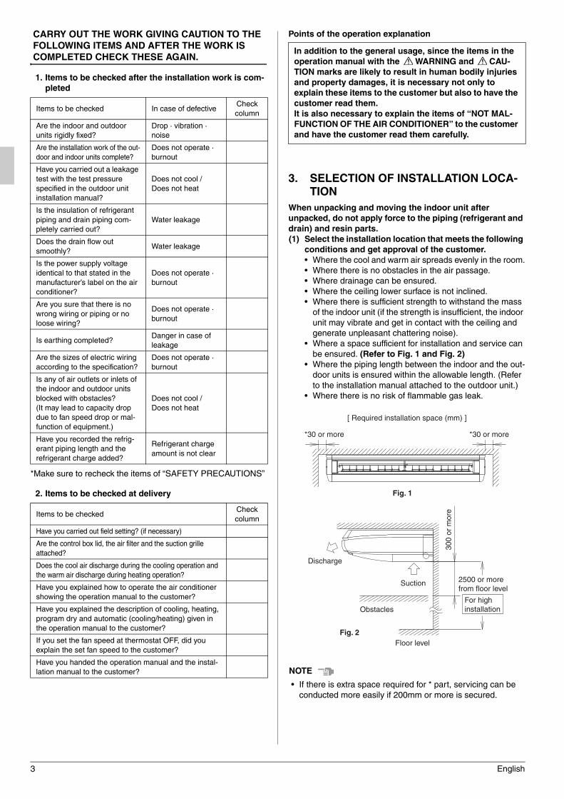
• Where a space sufficient for installation and service can
be ensured. (Refer to Fig. 1 and Fig. 2)
• Where the piping length between the indoor and the out-
door units is ensured within the allowable length. (Refer
to the installation manual attached to the outdoor unit.)
• Where there is no risk of flammable gas leak.
NOTENOTENOTENOTE
• If there is extra space required for * part, servicing can be
conducted more easily if 200mm or more is secured.
Items to be checked In case of defectiveCheck
column
Are the indoor and outdoor
units rigidly fixed?
Drop · vibration ·
noise
Are the installation work of the out-
door and indoor units complete?
Does not operate ·
burnout
Have you carried out a leakage
test with the test pressure
specified in the outdoor unit
installation manual?
Does not cool /
Does not heat
Is the insulation of refrigerant
piping and drain piping com-
pletely carried out?
Water leakage
Does the drain flow out
smoothly?Water leakage
Is the power supply voltage
identical to that stated in the
manufacturer’s label on the air
conditioner?
Does not operate ·
burnout
Are you sure that there is no
wrong wiring or piping or no
loose wiring?
Does not operate ·
burnout
Is earthing completed?Danger in case of
leakage
Are the sizes of electric wiring
according to the specification?
Does not operate ·
burnout
Is any of air outlets or inlets of
the indoor and outdoor units
blocked with obstacles?
(It may lead to capacity drop
due to fan speed drop or mal-
function of equipment.)
Does not cool /
Does not heat
Have you recorded the refrig-
erant piping length and the
refrigerant charge added?
Refrigerant charge
amount is not clear
Items to be checkedCheck
column
Have you carried out field setting? (if necessary)
Are the control box lid, the air filter and the suction grille
attached?
Does the cool air discharge during the cooling operation and
the warm air discharge during heating operation?
Have you explained how to operate the air conditioner
showing the operation manual to the customer?
Have you explained the description of cooling, heating,
program dry and automatic (cooling/heating) given in
the operation manual to the customer?
If you set the fan speed at thermostat OFF, did you
explain the set fan speed to the customer?
Have you handed the operation manual and the instal-
lation manual to the customer?
In addition to the general usage, since the items in the
operation manual with the WARNING and CAU-
TION marks are likely to result in human bodily injuries
and property damages, it is necessary not only to
explain these items to the customer but also to have the
customer read them.
It is also necessary to explain the items of “NOT MAL-
FUNCTION OF THE AIR CONDITIONER” to the customer
and have the customer read them carefully.
Fig. 1
[ Required installation space (mm) ]
*30 or more *30 or more
Fig. 2
Discharge
Obstacles
2500 or more from floor level
For high installation
Floor level
300
or m
ore
Suction
01_EN_3P368557-1.fm Page 3 Wednesday, December 10, 2014 10:31 AM
English 4
CAUTION
• Install the indoor and outdoor units, power supply wiring,
remote controller wiring and transmission wiring at least 1
meter away from televisions or radios to prevent image inter-
ference or noise.
(Depending on the radio waves, a distance of 1 meter may
not be sufficient to eliminate the noise.)
• Install the indoor unit as far as possible from fluorescent
lamps.
If a wireless remote controller kit is installed, the transmission
distance may be shorter in a room where an electronic lighting
type (inverter or rapid start type) fluorescent lamp is installed.
(2) Use hanging bolts for installation.
Investigate if the installation place can withstand the mass
of the indoor unit and, if necessary, hang the indoor unit
with bolts after it is reinforced by beams etc. (Refer to the
installation pattern paper (5) for the mounting pitch.).
(3) Ceiling height
This indoor unit can be installed up to 4.3m (for 35-71
model, 3.5m) of the ceiling.
4. PREPARATION BEFORE INSTALLATION
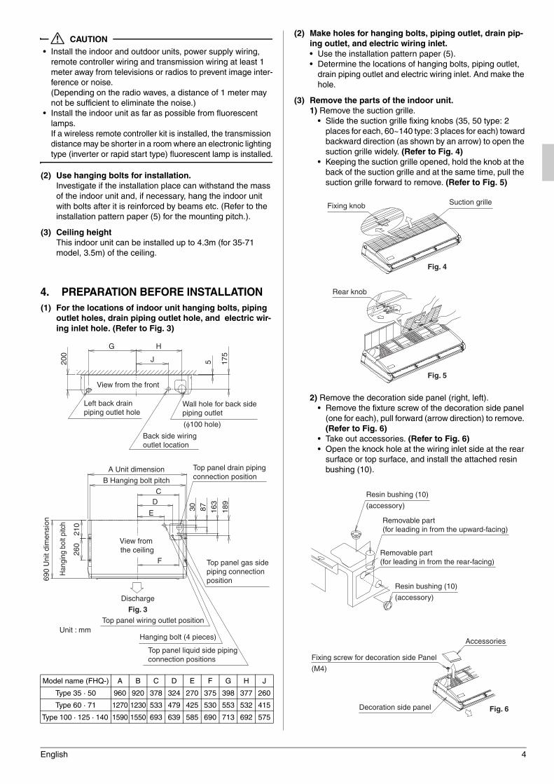
(1) For the locations of indoor unit hanging bolts, piping
outlet holes, drain piping outlet hole, and electric wir-
ing inlet hole. (Refer to Fig. 3)
(2) Make holes for hanging bolts, piping outlet, drain pip-
ing outlet, and electric wiring inlet.
• Use the installation pattern paper (5).
• Determine the locations of hanging bolts, piping outlet,
drain piping outlet and electric wiring inlet. And make the
hole.
(3) Remove the parts of the indoor unit.
1) Remove the suction grille.
• Slide the suction grille fixing knobs (35, 50 type: 2
places for each, 60~140 type: 3 places for each) toward
backward direction (as shown by an arrow) to open the
suction grille widely. (Refer to Fig. 4)
• Keeping the suction grille opened, hold the knob at the
back of the suction grille and at the same time, pull the
suction grille forward to remove. (Refer to Fig. 5)
2) Remove the decoration side panel (right, left).
• Remove the fixture screw of the decoration side panel
(one for each), pull forward (arrow direction) to remove.
(Refer to Fig. 6)
• Take out accessories. (Refer to Fig. 6)
• Open the knock hole at the wiring inlet side at the rear
surface or top surface, and install the attached resin
bushing (10).
Model name (FHQ-) A B C D E F G H J
Type 35 · 50 960 920 378 324 270 375 398 377 260
Type 60 · 71 1270 1230 533 479 425 530 553 532 415
Type 100 · 125 · 140 1590 1550 693 639 585 690 713 692 575
G H
J 5 175
200
View from the front
Left back drainpiping outlet hole
Wall hole for back side piping outlet
(φ100 hole)
Back side wiring outlet location
Fig. 3
F
690
Uni
t dim
ensi
on
210
D
A Unit dimension
B Hanging bolt pitch
View from the ceiling26
0
30 163
E 189
87
C
Discharge
Unit : mm
Top panel drain piping connection position
Top panel gas side piping connection position
Top panel liquid side piping connection positions
Top panel wiring outlet position
Hanging bolt (4 pieces)
Han
ging
bol
t pitc
h
Fig. 4
Fig. 5
Fixing knob Suction grille
Rear knob
Resin bushing (10)
(accessory)
Removable part (for leading in from the upward-facing)
Resin bushing (10)
(accessory)
Removable part (for leading in from the rear-facing)
Fig. 6
Fixing screw for decoration side Panel
(M4)
Decoration side panel
Accessories
01_EN_3P368557-1.fm Page 4 Wednesday, December 10, 2014 10:31 AM
5 English
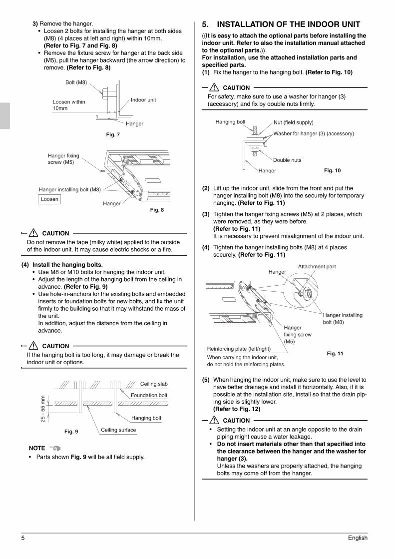
3) Remove the hanger.
• Loosen 2 bolts for installing the hanger at both sides
(M8) (4 places at left and right) within 10mm.
(Refer to Fig. 7 and Fig. 8)
• Remove the fixture screw for hanger at the back side
(M5), pull the hanger backward (the arrow direction) to
remove. (Refer to Fig. 8)
CAUTION
Do not remove the tape (milky white) applied to the outside
of the indoor unit. It may cause electric shocks or a fire.
(4) Install the hanging bolts.
• Use M8 or M10 bolts for hanging the indoor unit.
• Adjust the length of the hanging bolt from the ceiling in
advance. (Refer to Fig. 9)
• Use hole-in-anchors for the existing bolts and embedded
inserts or foundation bolts for new bolts, and fix the unit
firmly to the building so that it may withstand the mass of
the unit.
In addition, adjust the distance from the ceiling in
advance.
CAUTION
If the hanging bolt is too long, it may damage or break the
indoor unit or options.
NOTE
• Parts shown Fig. 9 will be all field supply.
5. INSTALLATION OF THE INDOOR UNIT
It is easy to attach the optional parts before installing the
indoor unit. Refer to also the installation manual attached
to the optional parts.For installation, use the attached installation parts and
specified parts.
(1) Fix the hanger to the hanging bolt. (Refer to Fig. 10)
CAUTION
For safety, make sure to use a washer for hanger (3)
(accessory) and fix by double nuts firmly.
(2) Lift up the indoor unit, slide from the front and put the
hanger installing bolt (M8) into the securely for temporary
hanging. (Refer to Fig. 11)
(3) Tighten the hanger fixing screws (M5) at 2 places, which
were removed, as they were before.
(Refer to Fig. 11)
It is necessary to prevent misalignment of the indoor unit.
(4) Tighten the hanger installing bolts (M8) at 4 places
securely. (Refer to Fig. 11)
(5) When hanging the indoor unit, make sure to use the level to
have better drainage and install it horizontally. Also, if it is
possible at the installation site, install so that the drain pip-
ing side is slightly lower.
(Refer to Fig. 12)
CAUTION
• Setting the indoor unit at an angle opposite to the drain
piping might cause a water leakage.
• Do not insert materials other than that specified into
the clearance between the hanger and the washer for
hanger (3).
Unless the washers are properly attached, the hanging
bolts may come off from the hanger.
Fig. 7
Bolt (M8)
Indoor unit
Hanger
Loosen within10mm
Fig. 8
Hanger fixing screw (M5)
Hanger installing bolt (M8)
HangerLoosen
Fig. 9 Ceiling surface
Hanging bolt
Foundation bolt
Ceiling slab
25 -
55
mm
Hanger
Nut (field supply)Hanging bolt
Washer for hanger (3) (accessory)
Double nuts
Fig. 10
Hanger fixing screw (M5)
Attachment partHanger
Reinforcing plate (left/right)
When carrying the indoor unit, do not hold the reinforcing plates.
Hanger installing bolt (M8)
Fig. 11
01_EN_3P368557-1.fm Page 5 Wednesday, December 10, 2014 10:31 AM
English 6
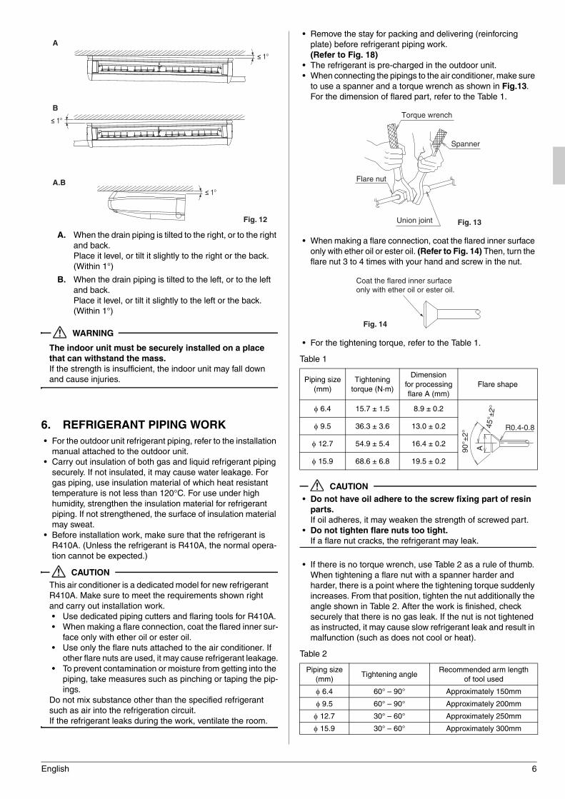
A. When the drain piping is tilted to the right, or to the right
and back.
Place it level, or tilt it slightly to the right or the back.
(Within 1°)
B. When the drain piping is tilted to the left, or to the left
and back.
Place it level, or tilt it slightly to the left or the back.
(Within 1°)
WARNING
The indoor unit must be securely installed on a place
that can withstand the mass.
If the strength is insufficient, the indoor unit may fall down
and cause injuries.
6. REFRIGERANT PIPING WORK
• For the outdoor unit refrigerant piping, refer to the installation
manual attached to the outdoor unit.
• Carry out insulation of both gas and liquid refrigerant piping
securely. If not insulated, it may cause water leakage. For
gas piping, use insulation material of which heat resistant
temperature is not less than 120°C. For use under high
humidity, strengthen the insulation material for refrigerant
piping. If not strengthened, the surface of insulation material
may sweat.
• Before installation work, make sure that the refrigerant is
R410A. (Unless the refrigerant is R410A, the normal opera-
tion cannot be expected.)
CAUTION
This air conditioner is a dedicated model for new refrigerant
R410A. Make sure to meet the requirements shown right
and carry out installation work.
• Use dedicated piping cutters and flaring tools for R410A.
• When making a flare connection, coat the flared inner sur-
face only with ether oil or ester oil.
• Use only the flare nuts attached to the air conditioner. If
other flare nuts are used, it may cause refrigerant leakage.
• To prevent contamination or moisture from getting into the
piping, take measures such as pinching or taping the pip-
ings.
Do not mix substance other than the specified refrigerant
such as air into the refrigeration circuit.
If the refrigerant leaks during the work, ventilate the room.
• Remove the stay for packing and delivering (reinforcing
plate) before refrigerant piping work.
(Refer to Fig. 18)
• The refrigerant is pre-charged in the outdoor unit.
• When connecting the pipings to the air conditioner, make sure
to use a spanner and a torque wrench as shown in Fig.13.
For the dimension of flared part, refer to the Table 1.
• When making a flare connection, coat the flared inner surface
only with ether oil or ester oil. (Refer to Fig. 14) Then, turn the
flare nut 3 to 4 times with your hand and screw in the nut.
• For the tightening torque, refer to the Table 1.
Table 1
CAUTION
• Do not have oil adhere to the screw fixing part of resin
parts.
If oil adheres, it may weaken the strength of screwed part.
• Do not tighten flare nuts too tight.
If a flare nut cracks, the refrigerant may leak.
• If there is no torque wrench, use Table 2 as a rule of thumb.
When tightening a flare nut with a spanner harder and
harder, there is a point where the tightening torque suddenly
increases. From that position, tighten the nut additionally the
angle shown in Table 2. After the work is finished, check
securely that there is no gas leak. If the nut is not tightened
as instructed, it may cause slow refrigerant leak and result in
malfunction (such as does not cool or heat).
Table 2
A
A.B
B
≤ 1°
≤ 1°
≤ 1°
Fig. 12
Piping size
(mm)
Tightening
torque (N·m)
Dimension
for processing
flare A (mm)
Flare shape
6.4 15.7 ± 1.5 8.9 ± 0.2
9.5 36.3 ± 3.6 13.0 ± 0.2
12.7 54.9 ± 5.4 16.4 ± 0.2
15.9 68.6 ± 6.8 19.5 ± 0.2
Piping size
(mm)Tightening angle
Recommended arm length
of tool used
6.4 60° – 90° Approximately 150mm
9.5 60° – 90° Approximately 200mm
12.7 30° – 60° Approximately 250mm
15.9 30° – 60° Approximately 300mm
Torque wrench
Spanner
Flare nut
Union joint Fig. 13
Coat the flared inner surface only with ether oil or ester oil.
Fig. 14
R0.4-0.8
90°±
2°
A45
°±2°
01_EN_3P368557-1.fm Page 6 Wednesday, December 10, 2014 10:31 AM
7 English
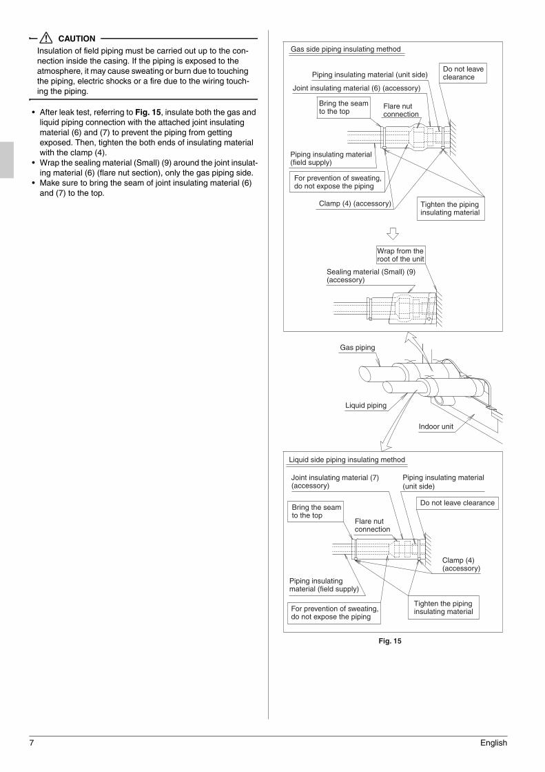
CAUTION
Insulation of field piping must be carried out up to the con-
nection inside the casing. If the piping is exposed to the
atmosphere, it may cause sweating or burn due to touching
the piping, electric shocks or a fire due to the wiring touch-
ing the piping.
• After leak test, referring to Fig. 15, insulate both the gas and
liquid piping connection with the attached joint insulating
material (6) and (7) to prevent the piping from getting
exposed. Then, tighten the both ends of insulating material
with the clamp (4).
• Wrap the sealing material (Small) (9) around the joint insulat-
ing material (6) (flare nut section), only the gas piping side.
• Make sure to bring the seam of joint insulating material (6)
and (7) to the top.
Joint insulating material (6) (accessory)
Gas side piping insulating method
Piping insulating material (unit side)Do not leave clearance
Wrap from the root of the unit
Sealing material (Small) (9)(accessory)
Bring the seam to the top
Flare nut connection
Piping insulating material(field supply)
For prevention of sweating, do not expose the piping
Clamp (4) (accessory) Tighten the piping insulating material
Liquid side piping insulating method
Joint insulating material (7)(accessory)
Flare nut connection
Piping insulating material (field supply)
For prevention of sweating, do not expose the piping
Fig. 15
Gas piping
Liquid piping
Indoor unit
Bring the seam to the top
Piping insulating material(unit side)
Do not leave clearance
Clamp (4) (accessory)
Tighten the piping insulating material
01_EN_3P368557-1.fm Page 7 Wednesday, December 10, 2014 10:31 AM
English 8
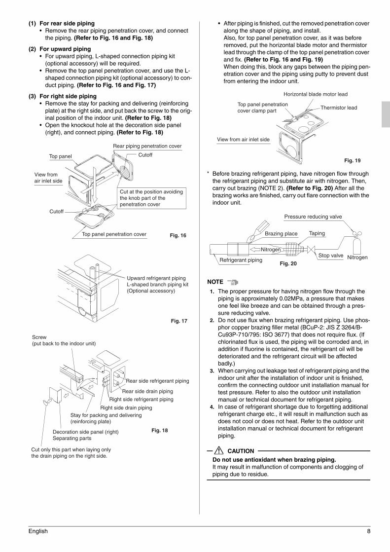
(1) For rear side piping
• Remove the rear piping penetration cover, and connect
the piping. (Refer to Fig. 16 and Fig. 18)
(2) For upward piping
• For upward piping, L-shaped connection piping kit
(optional accessory) will be required.
• Remove the top panel penetration cover, and use the L-
shaped connection piping kit (optional accessory) to con-
duct piping. (Refer to Fig. 16 and Fig. 17)
(3) For right side piping
• Remove the stay for packing and delivering (reinforcing
plate) at the right side, and put back the screw to the orig-
inal position of the indoor unit. (Refer to Fig. 18)
• Open the knockout hole at the decoration side panel
(right), and connect piping. (Refer to Fig. 18)
• After piping is finished, cut the removed penetration cover
along the shape of piping, and install.
Also, for top panel penetration cover, as it was before
removed, put the horizontal blade motor and thermistor
lead through the clamp of the top panel penetration cover
and fix. (Refer to Fig. 16 and Fig. 19)
When doing this, block any gaps between the piping pen-
etration cover and the piping using putty to prevent dust
from entering the indoor unit.
* Before brazing refrigerant piping, have nitrogen flow through
the refrigerant piping and substitute air with nitrogen. Then,
carry out brazing (NOTE 2). (Refer to Fig. 20) After all the
brazing works are finished, carry out flare connection with the
indoor unit.
NOTENOTENOTENOTE
1. The proper pressure for having nitrogen flow through the
piping is approximately 0.02MPa, a pressure that makes
one feel like breeze and can be obtained through a pres-
sure reducing valve.
2. Do not use flux when brazing refrigerant piping. Use phos-
phor copper brazing filler metal (BCuP-2: JIS Z 3264/B-
Cu93P-710/795: ISO 3677) that does not require flux. (If
chlorinated flux is used, the piping will be corroded and, in
addition if fluorine is contained, the refrigerant oil will be
deteriorated and the refrigerant circuit will be affected
badly.)
3. When carrying out leakage test of refrigerant piping and the
indoor unit after the installation of indoor unit is finished,
confirm the connecting outdoor unit installation manual for
test pressure. Refer to also the outdoor unit installation
manual or technical document for refrigerant piping.
4. In case of refrigerant shortage due to forgetting additional
refrigerant charge etc., it will result in malfunction such as
does not cool or does not heat. Refer to the outdoor unit
installation manual or technical document for refrigerant
piping.
CAUTION
Do not use antioxidant when brazing piping.
It may result in malfunction of components and clogging of
piping due to residue.
Top panel penetration cover
Cut at the position avoidingthe knob part of the penetration cover
Rear piping penetration cover
View from air inlet side
Cutoff
Cutoff
Top panel
Fig. 16
Upward refrigerant piping L-shaped branch piping kit (Optional accessory)
Fig. 17
Screw(put back to the indoor unit)
Decoration side panel (right)Separating parts
Cut only this part when laying only the drain piping on the right side.
Stay for packing and delivering(reinforcing plate)
Right side refrigerant piping
Rear side drain piping
Rear side refrigerant piping
Right side drain piping
Fig. 18
Thermistor lead
Horizontal blade motor lead
Top panel penetration cover clamp part
Fig. 19
View from air inlet side
Pressure reducing valve
Brazing place Taping
Stop valveNitrogen
NitrogenRefrigerant pipingFig. 20
01_EN_3P368557-1.fm Page 8 Wednesday, December 10, 2014 10:31 AM
9 English
7. DRAIN PIPING WORK
(1) Carry out drain piping.
• Carry out drain piping so that drainage can ensured.
• Drain piping can be connected from the following direc-
tions: For right rear/right side, refer to Fig. 18 of ‘‘6.
REFRIGERANT PIPING WORK’’, and for left rear/left
side, refer to Fig. 21.
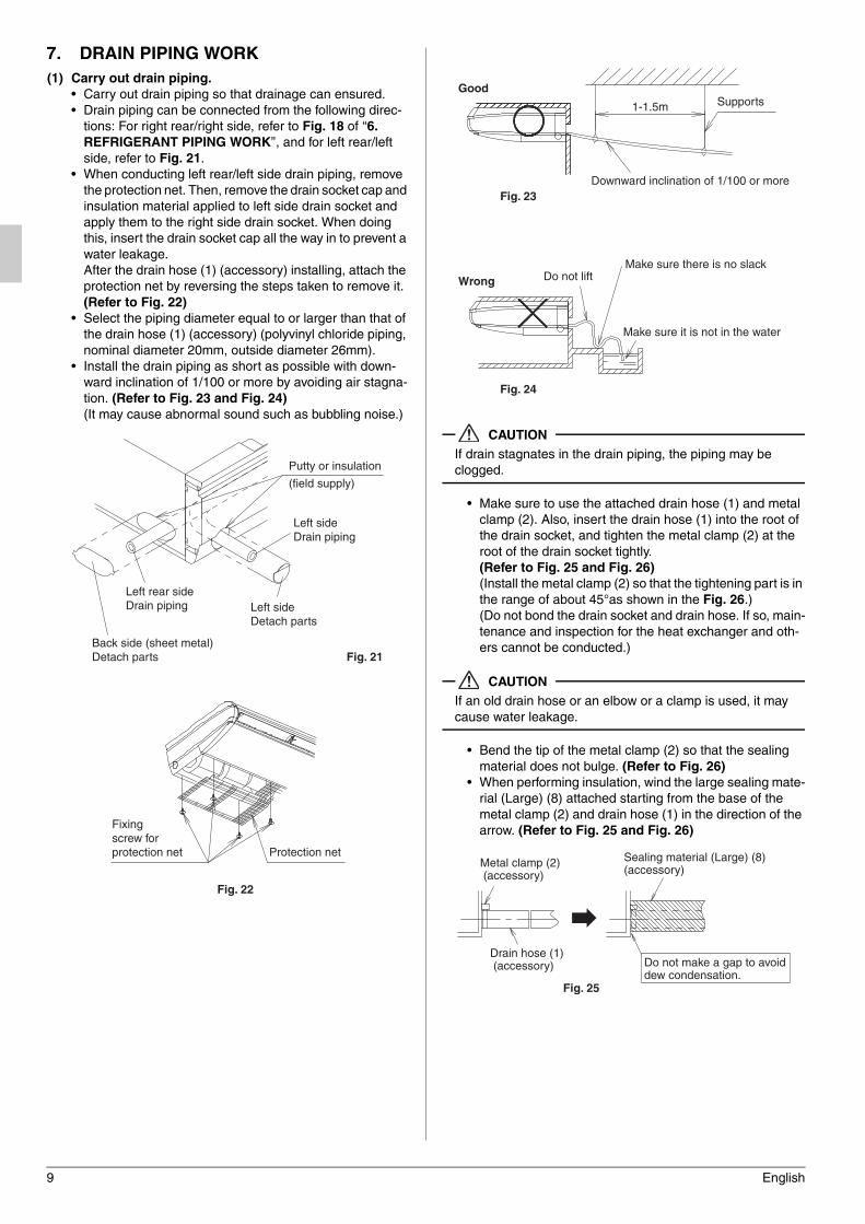
• When conducting left rear/left side drain piping, remove
the protection net. Then, remove the drain socket cap and
insulation material applied to left side drain socket and
apply them to the right side drain socket. When doing
this, insert the drain socket cap all the way in to prevent a
water leakage.
After the drain hose (1) (accessory) installing, attach the
protection net by reversing the steps taken to remove it.
(Refer to Fig. 22)
• Select the piping diameter equal to or larger than that of
the drain hose (1) (accessory) (polyvinyl chloride piping,
nominal diameter 20mm, outside diameter 26mm).
• Install the drain piping as short as possible with down-
ward inclination of 1/100 or more by avoiding air stagna-
tion. (Refer to Fig. 23 and Fig. 24)
(It may cause abnormal sound such as bubbling noise.)
CAUTION
If drain stagnates in the drain piping, the piping may be
clogged.
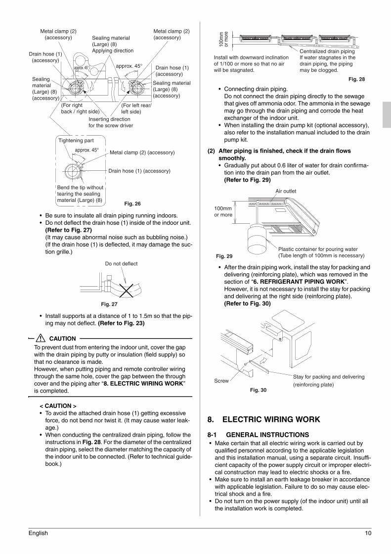
• Make sure to use the attached drain hose (1) and metal
clamp (2). Also, insert the drain hose (1) into the root of
the drain socket, and tighten the metal clamp (2) at the
root of the drain socket tightly.
(Refer to Fig. 25 and Fig. 26)
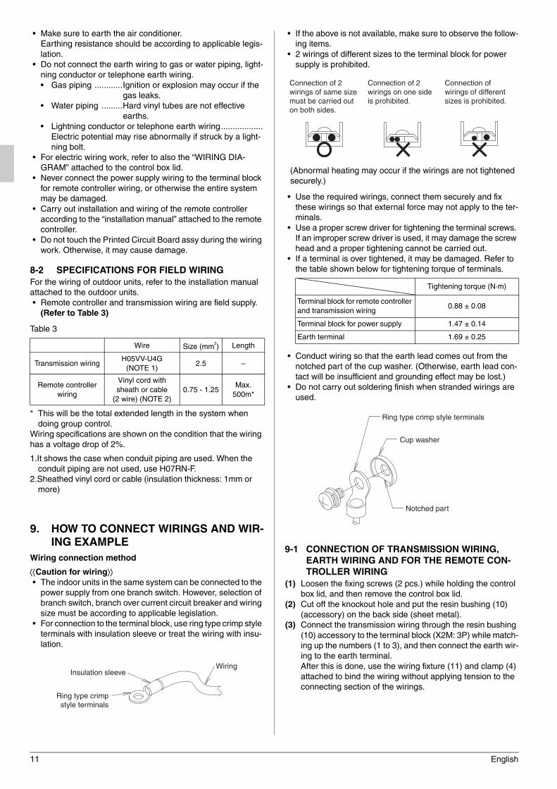
(Install the metal clamp (2) so that the tightening part is in
the range of about 45°as shown in the Fig. 26.)
(Do not bond the drain socket and drain hose. If so, main-
tenance and inspection for the heat exchanger and oth-
ers cannot be conducted.)
CAUTION
If an old drain hose or an elbow or a clamp is used, it may
cause water leakage.
• Bend the tip of the metal clamp (2) so that the sealing
material does not bulge. (Refer to Fig. 26)
• When performing insulation, wind the large sealing mate-
rial (Large) (8) attached starting from the base of the
metal clamp (2) and drain hose (1) in the direction of the
arrow. (Refer to Fig. 25 and Fig. 26)
Back side (sheet metal)Detach parts
Putty or insulation
(field supply)
Left sideDrain piping
Left sideDetach parts
Left rear sideDrain piping
Fig. 21
Protection net
Fixing screw forprotection net
Fig. 22
Good
Wrong
Supports1-1.5m
Downward inclination of 1/100 or more
Do not liftMake sure there is no slack
Make sure it is not in the water
Fig. 23
Fig. 24
Sealing material (Large) (8)(accessory)
Metal clamp (2) (accessory)
Drain hose (1) (accessory)
Fig. 25
Do not make a gap to avoid dew condensation.
01_EN_3P368557-1.fm Page 9 Wednesday, December 10, 2014 10:31 AM
English 10
• Be sure to insulate all drain piping running indoors.
• Do not deflect the drain hose (1) inside of the indoor unit.
(Refer to Fig. 27)
(It may cause abnormal noise such as bubbling noise.)
(If the drain hose (1) is deflected, it may damage the suc-
tion grille.)
• Install supports at a distance of 1 to 1.5m so that the pip-
ing may not deflect. (Refer to Fig. 23)
CAUTION
To prevent dust from entering the indoor unit, cover the gap
with the drain piping by putty or insulation (field supply) so
that no clearance is made.
However, when putting piping and remote controller wiring
through the same hole, cover the gap between the through
cover and the piping after ‘‘8. ELECTRIC WIRING WORK’’
is completed.
< CAUTION >
• To avoid the attached drain hose (1) getting excessive
force, do not bend nor twist it. (It may cause water leak-
age.)
• When conducting the centralized drain piping, follow the
instructions in Fig. 28. For the diameter of the centralized
drain piping, select the diameter matching the capacity of
the indoor unit to be connected. (Refer to technical guide-
book.)
• Connecting drain piping.
Do not connect the drain piping directly to the sewage
that gives off ammonia odor. The ammonia in the sewage
may go through the drain piping and corrode the heat
exchanger of the indoor unit.
• When installing the drain pump kit (optional accessory),
also refer to the installation manual included to the drain
pump kit.
(2) After piping is finished, check if the drain flows
smoothly.
• Gradually put about 0.6 liter of water for drain confirma-
tion into the drain pan from the air outlet.
(Refer to Fig. 29)
• After the drain piping work, install the stay for packing and
delivering (reinforcing plate), which was removed in the
section of ‘‘6. REFRIGERANT PIPING WORK’’.
However, it is not necessary to install the stay for packing
and delivering at the right side (reinforcing plate).
(Refer to Fig. 30)
8. ELECTRIC WIRING WORK
8-1 GENERAL INSTRUCTIONS
• Make certain that all electric wiring work is carried out by
qualified personnel according to the applicable legislation
and this installation manual, using a separate circuit. Insuffi-
cient capacity of the power supply circuit or improper electri-
cal construction may lead to electric shocks or a fire.
• Make sure to install an earth leakage breaker in accordance
with applicable legislation. Failure to do so may cause elec-
trical shock and a fire.
• Do not turn on the power supply (of the indoor unit) until all
the installation work is completed.
Sealing material (Large) (8)(accessory)
Sealing material (Large) (8)(accessory)
Metal clamp (2)(accessory)
Metal clamp (2)(accessory)
Drain hose (1)(accessory)
Drain hose (1)(accessory)
(For left rear/left side)
(For right back / right side)
Inserting direction for the screw driver
approx. 45° approx. 45°
Sealing material (Large) (8)Applying direction
Fig. 26
Tightening part
Metal clamp (2) (accessory)
Drain hose (1) (accessory)
approx. 45°
Bend the tip without tearing the sealing material (Large) (8)
Do not deflect
Fig. 27
Centralized drain pipingIf water stagnates in the drain piping, the piping may be clogged.
100m
m
or m
ore
Install with downward inclination of 1/100 or more so that no air will be stagnated.
Fig. 28
Plastic container for pouring water(Tube length of 100mm is necessary)
100mm or more
Air outlet
Fig. 29
ScrewStay for packing and delivering
(reinforcing plate)Fig. 30
01_EN_3P368557-1.fm Page 10 Wednesday, December 10, 2014 10:31 AM
11 English
• Make sure to earth the air conditioner.
Earthing resistance should be according to applicable legis-
lation.
• Do not connect the earth wiring to gas or water piping, light-
ning conductor or telephone earth wiring.
• Gas piping ............Ignition or explosion may occur if the
gas leaks.
• Water piping .........Hard vinyl tubes are not effective
earths.
• Lightning conductor or telephone earth wiring..................
Electric potential may rise abnormally if struck by a light-
ning bolt.
• For electric wiring work, refer to also the “WIRING DIA-
GRAM” attached to the control box lid.
• Never connect the power supply wiring to the terminal block
for remote controller wiring, or otherwise the entire system
may be damaged.
• Carry out installation and wiring of the remote controller
according to the “installation manual” attached to the remote
controller.
• Do not touch the Printed Circuit Board assy during the wiring
work. Otherwise, it may cause damage.
8-2 SPECIFICATIONS FOR FIELD WIRING
For the wiring of outdoor units, refer to the installation manual
attached to the outdoor units.
• Remote controller and transmission wiring are field supply.
(Refer to Table 3)
Table 3
* This will be the total extended length in the system when
doing group control.
Wiring specifications are shown on the condition that the wiring
has a voltage drop of 2%.
1.It shows the case when conduit piping are used. When the
conduit piping are not used, use H07RN-F.
2.Sheathed vinyl cord or cable (insulation thickness: 1mm or
more)
9. HOW TO CONNECT WIRINGS AND WIR-
ING EXAMPLE
Wiring connection method
Caution for wiring• The indoor units in the same system can be connected to the
power supply from one branch switch. However, selection of
branch switch, branch over current circuit breaker and wiring
size must be according to applicable legislation.
• For connection to the terminal block, use ring type crimp style
terminals with insulation sleeve or treat the wiring with insu-
lation.
• If the above is not available, make sure to observe the follow-
ing items.
• 2 wirings of different sizes to the terminal block for power
supply is prohibited.
(Abnormal heating may occur if the wirings are not tightened
securely.)
• Use the required wirings, connect them securely and fix
these wirings so that external force may not apply to the ter-
minals.
• Use a proper screw driver for tightening the terminal screws.
If an improper screw driver is used, it may damage the screw
head and a proper tightening cannot be carried out.
• If a terminal is over tightened, it may be damaged. Refer to
the table shown below for tightening torque of terminals.
• Conduct wiring so that the earth lead comes out from the
notched part of the cup washer. (Otherwise, earth lead con-
tact will be insufficient and grounding effect may be lost.)
• Do not carry out soldering finish when stranded wirings are
used.
9-1 CONNECTION OF TRANSMISSION WIRING,
EARTH WIRING AND FOR THE REMOTE CON-
TROLLER WIRING
(1) Loosen the fixing screws (2 pcs.) while holding the control
box lid, and then remove the control box lid.
(2) Cut off the knockout hole and put the resin bushing (10)
(accessory) on the back side (sheet metal).
(3) Connect the transmission wiring through the resin bushing
(10) accessory to the terminal block (X2M: 3P) while match-
ing up the numbers (1 to 3), and then connect the earth wir-
ing to the earth terminal.
After this is done, use the wiring fixture (11) and clamp (4)
attached to bind the wiring without applying tension to the
connecting section of the wirings.
Wire Size (mm2
) Length
Transmission wiringH05VV-U4G
(NOTE 1)2.5 –
Remote controller
wiring
Vinyl cord with
sheath or cable
(2 wire) (NOTE 2)
0.75 - 1.25Max.
500m*
Insulation sleeve
Ring type crimp style terminals
Wiring
Tightening torque (N·m)
Terminal block for remote controller
and transmission wiring0.88 ± 0.08
Terminal block for power supply 1.47 ± 0.14
Earth terminal 1.69 ± 0.25
Connection of 2 wirings of same size must be carried out on both sides.
Connection of wirings of different sizes is prohibited.
Connection of 2 wirings on one side is prohibited.
Notched part
Ring type crimp style terminals
Cup washer
01_EN_3P368557-1.fm Page 11 Wednesday, December 10, 2014 10:31 AM
English 12
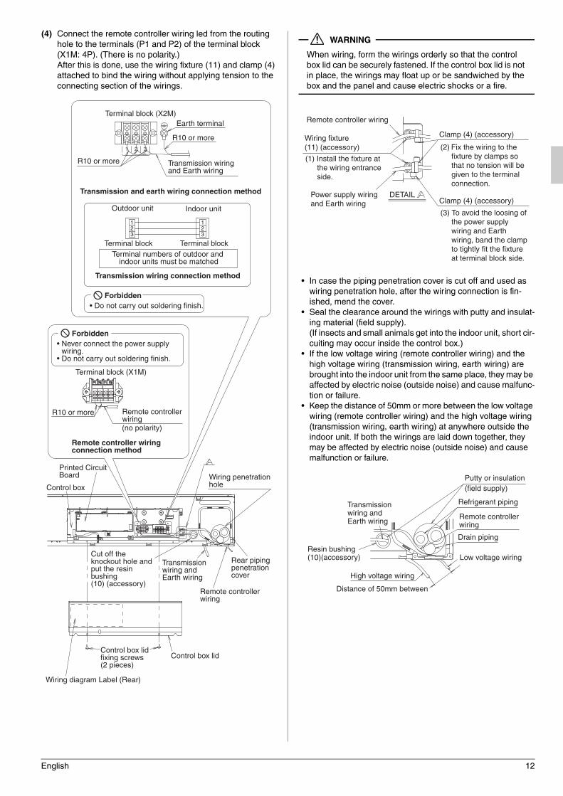
(4) Connect the remote controller wiring led from the routing
hole to the terminals (P1 and P2) of the terminal block
(X1M: 4P). (There is no polarity.)
After this is done, use the wiring fixture (11) and clamp (4)
attached to bind the wiring without applying tension to the
connecting section of the wirings.
WARNING
When wiring, form the wirings orderly so that the control
box lid can be securely fastened. If the control box lid is not
in place, the wirings may float up or be sandwiched by the
box and the panel and cause electric shocks or a fire.
• In case the piping penetration cover is cut off and used as
wiring penetration hole, after the wiring connection is fin-
ished, mend the cover.
• Seal the clearance around the wirings with putty and insulat-
ing material (field supply).
(If insects and small animals get into the indoor unit, short cir-
cuiting may occur inside the control box.)
• If the low voltage wiring (remote controller wiring) and the
high voltage wiring (transmission wiring, earth wiring) are
brought into the indoor unit from the same place, they may be
affected by electric noise (outside noise) and cause malfunc-
tion or failure.
• Keep the distance of 50mm or more between the low voltage
wiring (remote controller wiring) and the high voltage wiring
(transmission wiring, earth wiring) at anywhere outside the
indoor unit. If both the wirings are laid down together, they
may be affected by electric noise (outside noise) and cause
malfunction or failure.
Remote controller wiring
R10 or more
Terminal block (X2M)
R10 or more
Transmission and earth wiring connection method
R10 or more
Earth terminal
Outdoor unit Indoor unit
Terminal block Terminal blockTerminal numbers of outdoor and
indoor units must be matched
Transmission wiring connection method
Remote controller wiring connection method
(no polarity)
Wiring penetration hole
Rear piping penetration cover
Remote controller wiring
Cut off the knockout hole and put the resin bushing (10) (accessory)
Printed Circuit Board
Control box
Wiring diagram Label (Rear)
Control box lidfixing screws (2 pieces)
Control box lid
Transmission wiring and Earth wiring
Transmission wiring and Earth wiring
Terminal block (X1M)
Forbidden• Never connect the power supply
wiring.• Do not carry out soldering finish.
Forbidden• Do not carry out soldering finish.
Remote controller wiring
(1) Install the fixture at the wiring entrance side.
Power supply wiring and Earth wiring
DETAIL
Wiring fixture (11) (accessory)
Clamp (4) (accessory)
Clamp (4) (accessory)
(3) To avoid the loosing of the power supply wiring and Earth wiring, band the clamp to tightly fit the fixture at terminal block side.
(2) Fix the wiring to the fixture by clamps so that no tension will be given to the terminal connection.
Putty or insulation(field supply)
Refrigerant piping
Remote controller wiring
Low voltage wiring
Drain piping
Distance of 50mm between
High voltage wiring
Resin bushing (10)(accessory)
Transmission wiring and Earth wiring
01_EN_3P368557-1.fm Page 12 Wednesday, December 10, 2014 10:31 AM
13 English
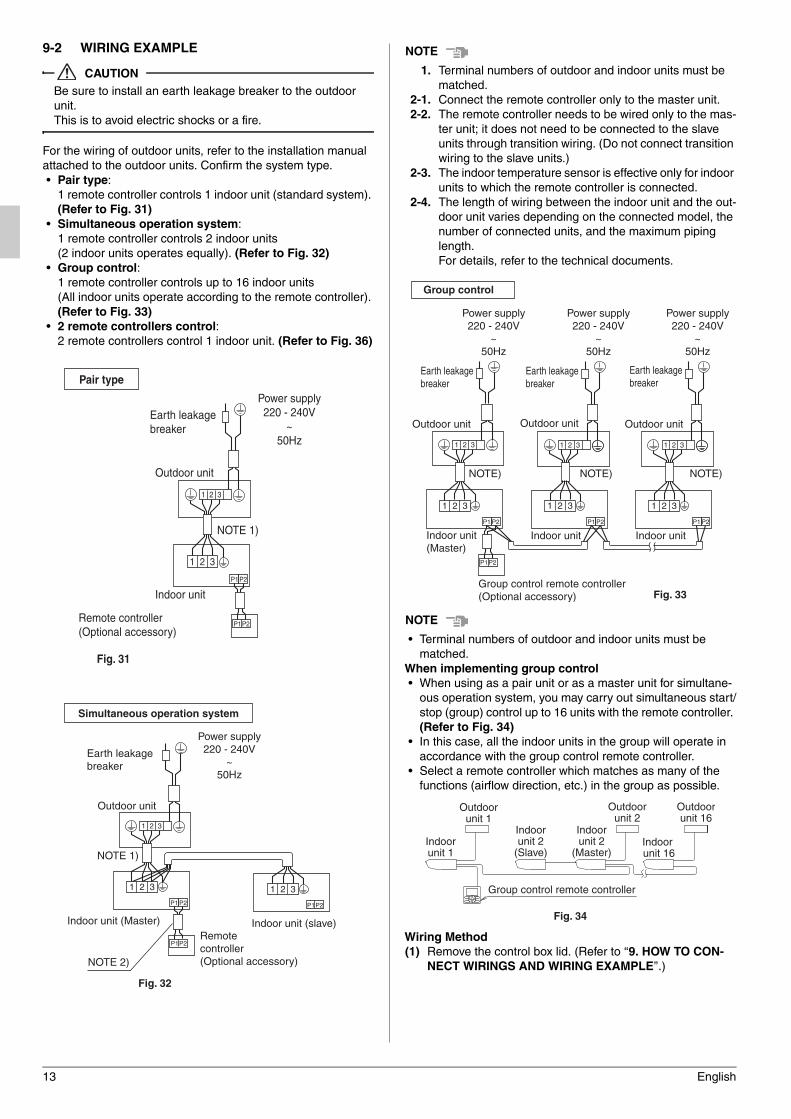
9-2 WIRING EXAMPLE
CAUTION
Be sure to install an earth leakage breaker to the outdoor
unit.
This is to avoid electric shocks or a fire.
For the wiring of outdoor units, refer to the installation manual
attached to the outdoor units. Confirm the system type.
• Pair type:
1 remote controller controls 1 indoor unit (standard system).
(Refer to Fig. 31)
• Simultaneous operation system:
1 remote controller controls 2 indoor units
(2 indoor units operates equally). (Refer to Fig. 32)
• Group control:
1 remote controller controls up to 16 indoor units
(All indoor units operate according to the remote controller).
(Refer to Fig. 33)
• 2 remote controllers control:
2 remote controllers control 1 indoor unit. (Refer to Fig. 36)
NOTENOTENOTENOTE
1. Terminal numbers of outdoor and indoor units must be
matched.
2-1. Connect the remote controller only to the master unit.
2-2. The remote controller needs to be wired only to the mas-
ter unit; it does not need to be connected to the slave
units through transition wiring. (Do not connect transition
wiring to the slave units.)
2-3. The indoor temperature sensor is effective only for indoor
units to which the remote controller is connected.
2-4. The length of wiring between the indoor unit and the out-
door unit varies depending on the connected model, the
number of connected units, and the maximum piping
length.
For details, refer to the technical documents.
NOTENOTENOTENOTE
• Terminal numbers of outdoor and indoor units must be
matched.
When implementing group control
• When using as a pair unit or as a master unit for simultane-
ous operation system, you may carry out simultaneous start/
stop (group) control up to 16 units with the remote controller.
(Refer to Fig. 34)
• In this case, all the indoor units in the group will operate in
accordance with the group control remote controller.
• Select a remote controller which matches as many of the
functions (airflow direction, etc.) in the group as possible.
Wiring Method
(1) Remove the control box lid. (Refer to ‘‘9. HOW TO CON-
NECT WIRINGS AND WIRING EXAMPLE’’.)
P1P2
1 2 3
P1 P2
1 2 3
Power supply220 - 240V
~50Hz
Earth leakage breaker
Outdoor unit
NOTE 1)
Indoor unit
Remote controller (Optional accessory)
Pair type
Fig. 31
1 2 3
P1P2
P1P2
P1 P2
1 2 3 1 2 3
Outdoor unit
Indoor unit (Master) Indoor unit (slave)Remote controller (Optional accessory)
Simultaneous operation system
Earth leakage breaker
NOTE 1)
Power supply220 - 240V
~50Hz
NOTE 2)
Fig. 32
P1P2
1 2 3 1 2 3 1 2 3
P1 P2 P1 P2 P1 P2
1 2 3 1 2 3 1 2 3
Outdoor unit
Indoor unit(Master)
Outdoor unit
Indoor unit Indoor unit
Outdoor unit
Group control remote controller (Optional accessory)
Earth leakage breaker
Earth leakage breaker
Earth leakage breaker
NOTE) NOTE) NOTE)
Power supply220 - 240V
~50Hz
Power supply220 - 240V
~50Hz
Power supply220 - 240V
~50Hz
Group control
Fig. 33
Fig. 34
Outdoorunit 1
Outdoorunit 2
Outdoorunit 16
Indoorunit 1
Group control remote controller
Indoorunit 2
(Slave)
Indoorunit 2
(Master)Indoor unit 16
01_EN_3P368557-1.fm Page 13 Wednesday, December 10, 2014 10:31 AM
English 14
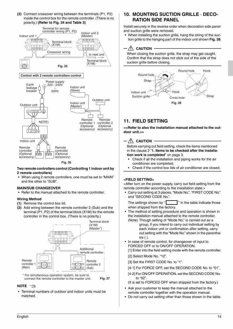
(2) Connect crossover wiring between the terminals (P1, P2)
inside the control box for the remote controller. (There is no
polarity.) (Refer to Fig. 34 and Table 3)
Two remote controllers control (Controlling 1 indoor unit by
2 remote controllers)
• When using 2 remote controllers, one must be set to “MAIN”
and the other to “SUB”.
MAIN/SUB CHANGEOVER
• Refer to the manual attached to the remote controller.
Wiring Method
(1) Remove the control box lid.
(2) Add wiring between the remote controller 2 (Sub) and the
terminal (P1, P2) of the terminal block (X1M) for the remote
controller in the control box. (There is no polarity.)
NOTENOTENOTENOTE
• Terminal numbers of outdoor and indoor units must be
matched.
10. MOUNTING SUCTION GRILLE · DECO-
RATION SIDE PANEL
Install securely in the reverse order when decoration side panel
and suction grille were removed.
• When installing the suction grille, hang the string of the suc-
tion grille to the hanging part of the indoor unit shown Fig. 38.
CAUTION
When closing the suction grille, the strap may get caught.
Confirm that the strap does not stick out of the side of the
suction grille before closing.
11. FIELD SETTING
<<Refer to also the installation manual attached to the out-
door unit.>>
CAUTION
Before carrying out field setting, check the items mentioned
in the clause 2 “1. Items to be checked after the installa-
tion work is completed” on page 3.
• Check if all the installation and piping works for the air
conditioner are completed.
• Check if the control box lids of air conditioner are closed.
<FIELD SETTING>
<After turn on the power supply, carry out field setting from the
remote controller according to the installation state.>
• Carry out setting at 3 places, “Mode No.”, “FIRST CODE No.”
and “SECOND CODE No.”.
The settings shown by “ ” in the table indicate those
when shipped from the factory.
• The method of setting procedure and operation is shown in
the installation manual attached to the remote controller.
(Note) Though setting of “Mode No.” is carried out as a
group, if you intend to carry out individual setting by
each indoor unit or confirmation after setting, carry
out setting with the “Mode No.” shown in the parenthe-
sis ( ).
• In case of remote control, for changeover of input to
FORCED OFF or to ON/OFF OPERATION.
[1] Enter into the field setting mode with the remote controller.
[2] Select Mode No. “12”.
[3] Set the FIRST CODE No. to “1”.
[4-1] For FORCE OFF, set the SECOND CODE No. to “01”.
[4-2] For ON/OFF OPERATION, set the SECOND CODE No.
to “02”.
(It is set to FORCED OFF when shipped from the factory.)
• Ask your customer to keep the manual attached to the
remote controller together with the operation manual.
• Do not carry out setting other than those shown in the table.
Fig. 35
Terminal for remote controller wiring (P1, P2)
Crossover wiring
Terminal block (X1M)
to next unit
Terminal block (X1M)
Indoor unit 1Indoor unit 2 (Master)
F2P2 F1P1P2P1 F1 F2
P1 P2
P1P2 P1P2
1 2 3
1 2 3
Outdoor unit
NOTE)
Indoor unit
Remote controller(Optional accessory)
Remote controller(Optional accessory)
Control with 2 remote controllers control
Earth leakage breaker
Outdoor unit
Indoor unit(Slave)
Indoor unit (Master)
Remote controller 2(Optional accessory)
Remote controller 1(Optional accessory)
Power supply220 - 240V
~50Hz
Fig. 36
Fig. 37
Remote controller 1(Main)
Remote controller 2(Sub)
Terminal block (X1M)(Master*)
Additional remote controller
* For simultaneous operation system, be sure to connect the remote controller to the master unit.
P1 P2 F1 F2
Strap
Hook
Hook
Round holeRound hole
Cross hole
Strap
Indoor unitSuction grille
Fig. 38
01_EN_3P368557-1.fm Page 14 Wednesday, December 10, 2014 10:31 AM
15 English
11-1 SETTING WHEN AN OPTIONAL ACCESSORY
IS ATTACHED
• For setting when attaching an optional accessory, refer to the
installation manual attached to the optional accessory.
11-2 WHEN USING WIRELESS REMOTE CONTROL-
LER
• When using a wireless remote controller, it is necessary to
set the wireless remote controller address.
Refer to the installation manual attached to the wireless
remote controller.
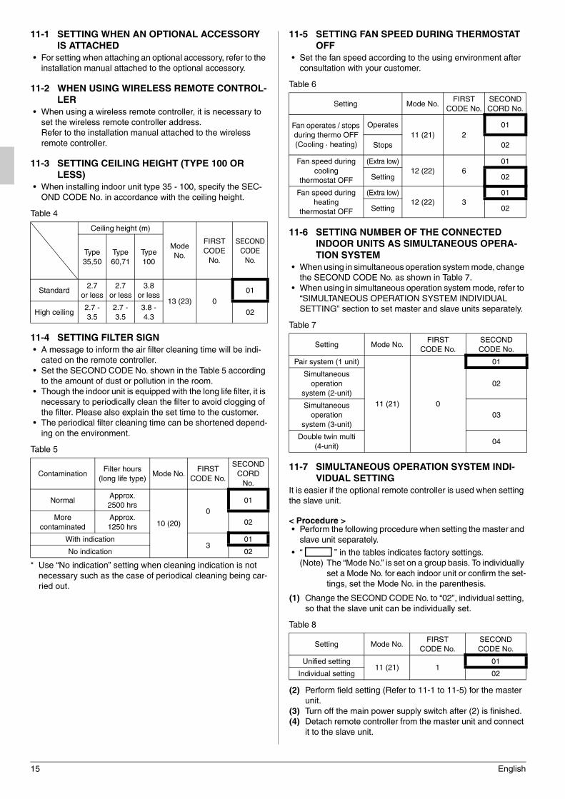
11-3 SETTING CEILING HEIGHT (TYPE 100 OR
LESS)
• When installing indoor unit type 35 - 100, specify the SEC-
OND CODE No. in accordance with the ceiling height.
Table 4
11-4 SETTING FILTER SIGN
• A message to inform the air filter cleaning time will be indi-
cated on the remote controller.
• Set the SECOND CODE No. shown in the Table 5 according
to the amount of dust or pollution in the room.
• Though the indoor unit is equipped with the long life filter, it is
necessary to periodically clean the filter to avoid clogging of
the filter. Please also explain the set time to the customer.
• The periodical filter cleaning time can be shortened depend-
ing on the environment.
Table 5
* Use “No indication” setting when cleaning indication is not
necessary such as the case of periodical cleaning being car-
ried out.
11-5 SETTING FAN SPEED DURING THERMOSTAT
OFF
• Set the fan speed according to the using environment after
consultation with your customer.
Table 6
11-6 SETTING NUMBER OF THE CONNECTED
INDOOR UNITS AS SIMULTANEOUS OPERA-
TION SYSTEM
• When using in simultaneous operation system mode, change
the SECOND CODE No. as shown in Table 7.
• When using in simultaneous operation system mode, refer to
“SIMULTANEOUS OPERATION SYSTEM INDIVIDUAL
SETTING” section to set master and slave units separately.
Table 7
11-7 SIMULTANEOUS OPERATION SYSTEM INDI-
VIDUAL SETTING
It is easier if the optional remote controller is used when setting
the slave unit.
< Procedure >• Perform the following procedure when setting the master and
slave unit separately.
• “ ” in the tables indicates factory settings.
(Note) The “Mode No.” is set on a group basis. To individually
set a Mode No. for each indoor unit or confirm the set-
tings, set the Mode No. in the parenthesis.
(1) Change the SECOND CODE No. to “02”, individual setting,
so that the slave unit can be individually set.
Table 8
(2) Perform field setting (Refer to 11-1 to 11-5) for the master
unit.
(3) Turn off the main power supply switch after (2) is finished.
(4) Detach remote controller from the master unit and connect
it to the slave unit.
Ceiling height (m)
Mode
No.
FIRST
CODE
No.
SECOND
CODE
No.Type
35,50
Type
60,71
Type
100
Standard2.7
or less
2.7
or less
3.8
or less13 (23) 0
01
High ceiling2.7 -
3.5
2.7 -
3.5
3.8 -
4.302
ContaminationFilter hours
(long life type)Mode No.
FIRST
CODE No.
SECOND
CORD
No.
NormalApprox.
2500 hrs
10 (20)
0
01
More
contaminated
Approx.
1250 hrs02
With indication3
01
No indication 02
Setting Mode No.FIRST
CODE No.
SECOND
CORD No.
Fan operates / stops
during thermo OFF
(Cooling · heating)
Operates
11 (21) 2
01
Stops 02
Fan speed during
cooling
thermostat OFF
(Extra low)
12 (22) 6
01
Setting 02
Fan speed during
heating
thermostat OFF
(Extra low)
12 (22) 3
01
Setting 02
Setting Mode No.FIRST
CODE No.
SECOND
CODE No.
Pair system (1 unit)
11 (21) 0
01
Simultaneous
operation
system (2-unit)
02
Simultaneous
operation
system (3-unit)
03
Double twin multi
(4-unit)04
Setting Mode No.FIRST
CODE No.
SECOND
CODE No.
Unified setting11 (21) 1
01
Individual setting 02
01_EN_3P368557-1.fm Page 15 Wednesday, December 10, 2014 10:31 AM
English 16
(5) Turn on the main power supply switch again, and as in (1),
change the SECOND CODE No. to “02”, individual setting.
(6) Perform field setting (Refer to 11-1 to 11-4) for the slave
unit.
(7) Turn off the main power supply switch after (6) is finished.
(8) If there is more than one slave unit, repeat steps (4) to (7).
(9) Detach the remote controller from the slave unit after the
setting, and reattach to the master unit. This is the end of
the setting procedure.
* You do not need to rewire the remote controller from the
master unit if the optional remote controller for slave unit
is used. (However, remove the wiring attached to the
remote controller terminal block of the master unit.) After
the slave unit setting, remove the remote controller wir-
ing, and rewire the remote controller to the master unit.
(The indoor unit does not operate properly when two or
more remote controllers are attached to the unit in the
simultaneous operation system mode.)
NOTENOTENOTENOTE
• Terminal numbers of outdoor and indoor units must be
matched.
12. TEST OPERATION
Complete all the “1. Items to be checked after the installa-
tion work is completed” on page 3. Please also refer to the
installation manual attached to with outdoor unit.(1) The settings of the wired remote controller should be
switched while referring to the manual attached to the
remote controller.
(2) The settings of the other remote controller should be
switched in accordance with the following procedure.
• Make sure that the installation work for the indoor and
outdoor units is all completed.
• Make sure that the following items are all closed: the
control box lid of the indoor unit and the outer board
and piping cover of the outdoor unit.
• After completing the refrigerant piping, drain piping,
and electrical wiring, clean the interior of the indoor unit
and front panel. Next, perform test operation in accor-
dance with the installation manual attached to with the
outdoor unit in order to protect the unit. (It is recom-
mended that the test operation is performed in the
presence of qualified electrical technician or engineer.)
• In test operation, make sure that airflow direction and
fan speed can be obtained according to the settings.
• If interior work is still unfinished when test operation fin-
ishes, explain to the customer that the air conditioner
must not be operated until interior work is completed in
order to protect the indoor units.
(If the indoor unit is operated under this condition,
paint, glue, and other materials used during the interior
finishing work will contaminate the indoor unit. This
may cause water splashes or leakage.)
• If a malfunction occurs and the air conditioner cannot
operate, refer to “12-1 HOW TO DIAGNOSE FOR
PROBLEMS”.
• After completing the test operation, press the INSPEC-
TION/TEST OPERATION button once to put the indoor
unit in inspection mode, and make sure the malfunction
code is “00” (= normal).
If the code reads anything other than “00”, refer to “12-
1 HOW TO DIAGNOSE FOR PROBLEMS”.
• Press the INSPECTION/TEST OPERATION button
four times to return to normal operation mode.
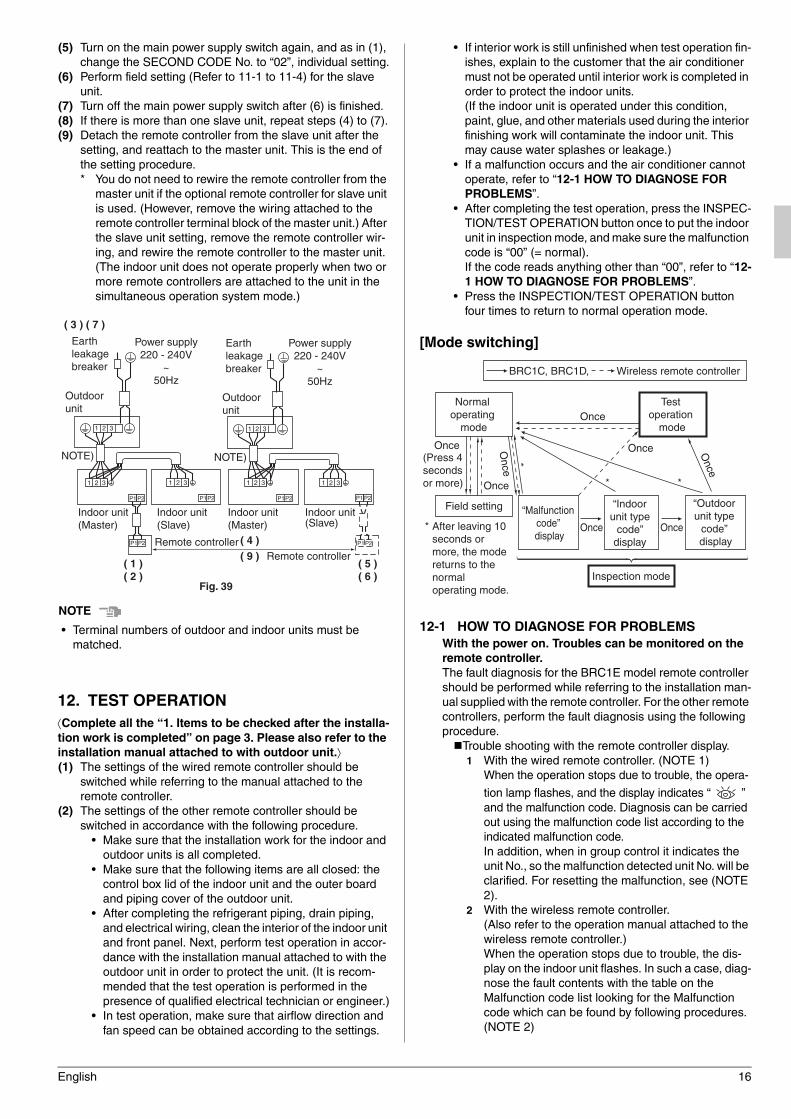
[Mode switching]
12-1 HOW TO DIAGNOSE FOR PROBLEMS
With the power on. Troubles can be monitored on the
remote controller.
The fault diagnosis for the BRC1E model remote controller
should be performed while referring to the installation man-
ual supplied with the remote controller. For the other remote
controllers, perform the fault diagnosis using the following
procedure.
Trouble shooting with the remote controller display.
1 With the wired remote controller. (NOTE 1)
When the operation stops due to trouble, the opera-
tion lamp flashes, and the display indicates “ ”
and the malfunction code. Diagnosis can be carried
out using the malfunction code list according to the
indicated malfunction code.
In addition, when in group control it indicates the
unit No., so the malfunction detected unit No. will be
clarified. For resetting the malfunction, see (NOTE
2).
2 With the wireless remote controller.
(Also refer to the operation manual attached to the
wireless remote controller.)
When the operation stops due to trouble, the dis-
play on the indoor unit flashes. In such a case, diag-
nose the fault contents with the table on the
Malfunction code list looking for the Malfunction
code which can be found by following procedures.
(NOTE 2)
P1P2
P1P2
1 2 3
P1P2
1 2 3
P1P2P1 P2 P1 P2
1 2 3 1 2 3 1 2 3 1 2 3
Outdoor unit
Outdoor unit
NOTE) NOTE)
Indoor unit (Master)
Indoor unit (Master)
Indoor unit (Slave)
Indoor unit (Slave)
Remote controllerRemote controller
( 3 ) ( 7 )
( 1 ) ( 2 )
( 4 )( 9 )
( 5 ) ( 6 )
Earth leakage breaker
Earth leakage breaker
Fig. 39
Power supply220 - 240V
~50Hz
Power supply220 - 240V
~50Hz
Normal operating
mode
BRC1C, BRC1D, Wireless remote controller
Test operation
mode
Inspection mode
Field setting
(Press 4 seconds or more) Once
Once
Once
Once
Once Once
Once Once
“Malfunction code” display
“Indoor unit type code” display
“Outdoor unit type
code” display
*
* *
* After leaving 10 seconds or more, the mode returns to the normal operating mode.
01_EN_3P368557-1.fm Page 16 Wednesday, December 10, 2014 10:31 AM
17 English
(1) Press the INSPECTION /TEST OPERATION but-
ton, “ ” is displayed and “ 0 ” flashes.
(2) Press the PROGRAMMING TIME button and find
the unit No. which stopped due to trouble.
Number of beeps 3 short beeps
................. Perform all the following operations
1 short beep
................. Perform (3) and (6)
1 long beep
................. No trouble
(3) Press the OPERATION MODE SELECTOR button
and upper figure of the malfunction code flashes.
(4) Continue pressing the PROGRAMMING TIME button
unit it makes 2 short beeps and find the upper code.
(5) Press the OPERATION MODE SELECTOR button
and lower figure of the malfunction code flashes.
(6) Continue pressing the PROGRAMMING TIME button
unit it makes a long beep and find the lower code.
• A long beep indicate the malfunction code.
NOTENOTENOTENOTE
1. When the INSPECTION/OPERATION button on the remote
controller is pressed, the “ ” indication starts flashing.
2. When the ON/OFF button is kept pressed for 5 seconds or
longer during the inspection mode, the above trouble his-
tory indication disappears. In this case, after the malfunc-
tion code indication flashes twice, the indication of code
becomes “00” (normal) and unit NO. becomes “0”. Then,
the display automatically changes from the inspection
mode to the normal mode.
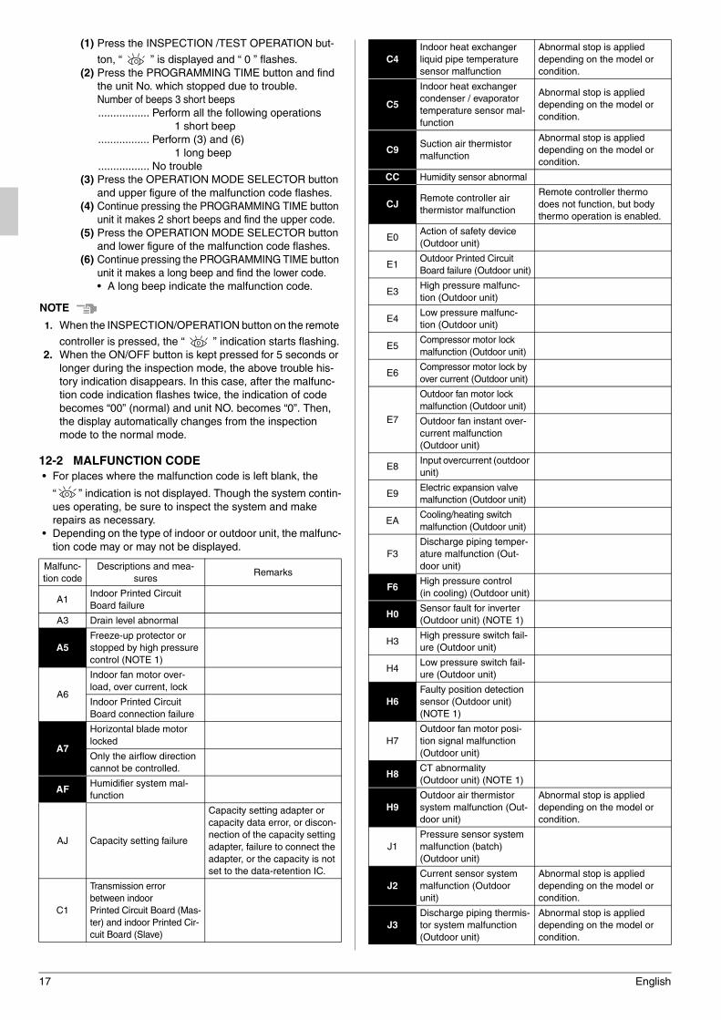
12-2 MALFUNCTION CODE
• For places where the malfunction code is left blank, the
“ ” indication is not displayed. Though the system contin-
ues operating, be sure to inspect the system and make
repairs as necessary.
• Depending on the type of indoor or outdoor unit, the malfunc-
tion code may or may not be displayed.
Malfunc-
tion code
Descriptions and mea-
suresRemarks
A1Indoor Printed Circuit
Board failure
A3 Drain level abnormal
A5
Freeze-up protector or
stopped by high pressure
control (NOTE 1)
A6
Indoor fan motor over-
load, over current, lock
Indoor Printed Circuit
Board connection failure
A7
Horizontal blade motor
locked
Only the airflow direction
cannot be controlled.
AFHumidifier system mal-
function
AJ Capacity setting failure
Capacity setting adapter or
capacity data error, or discon-
nection of the capacity setting
adapter, failure to connect the
adapter, or the capacity is not
set to the data-retention IC.
C1
Transmission error
between indoor
Printed Circuit Board (Mas-
ter) and indoor Printed Cir-
cuit Board (Slave)
C4
Indoor heat exchanger
liquid pipe temperature
sensor malfunction
Abnormal stop is applied
depending on the model or
condition.
C5
Indoor heat exchanger
condenser / evaporator
temperature sensor mal-
function
Abnormal stop is applied
depending on the model or
condition.
C9Suction air thermistor
malfunction
Abnormal stop is applied
depending on the model or
condition.
CC Humidity sensor abnormal
CJRemote controller air
thermistor malfunction
Remote controller thermo
does not function, but body
thermo operation is enabled.
E0Action of safety device
(Outdoor unit)
E1Outdoor Printed Circuit
Board failure (Outdoor unit)
E3High pressure malfunc-
tion (Outdoor unit)
E4Low pressure malfunc-
tion (Outdoor unit)
E5Compressor motor lock
malfunction (Outdoor unit)
E6Compressor motor lock by
over current (Outdoor unit)
E7
Outdoor fan motor lock
malfunction (Outdoor unit)
Outdoor fan instant over-
current malfunction
(Outdoor unit)
E8Input overcurrent (outdoor
unit)
E9Electric expansion valve
malfunction (Outdoor unit)
EACooling/heating switch
malfunction (Outdoor unit)
F3
Discharge piping temper-
ature malfunction (Out-
door unit)
F6High pressure control
(in cooling) (Outdoor unit)
H0Sensor fault for inverter
(Outdoor unit) (NOTE 1)
H3High pressure switch fail-
ure (Outdoor unit)
H4Low pressure switch fail-
ure (Outdoor unit)
H6
Faulty position detection
sensor (Outdoor unit)
(NOTE 1)
H7
Outdoor fan motor posi-
tion signal malfunction
(Outdoor unit)
H8CT abnormality
(Outdoor unit) (NOTE 1)
H9
Outdoor air thermistor
system malfunction (Out-
door unit)
Abnormal stop is applied
depending on the model or
condition.
J1
Pressure sensor system
malfunction (batch)
(Outdoor unit)
J2
Current sensor system
malfunction (Outdoor
unit)
Abnormal stop is applied
depending on the model or
condition.
J3
Discharge piping thermis-
tor system malfunction
(Outdoor unit)
Abnormal stop is applied
depending on the model or
condition.
01_EN_3P368557-1.fm Page 17 Wednesday, December 10, 2014 10:31 AM
English 18
CAUTION
After test operation is completed, check the items mentioned in
the clause 2 “2. Items to be checked at delivery” on page 3.
If the interior finish work is not completed when the test opera-
tion is finished, for protection of the air conditioner, ask the cus-
tomer not operate the air conditioner until the interior finish work
is completed.
If the air conditioner is operated, the inside of the indoor units
may be polluted by substances generated from the coating and
adhesives used for the interior finish work and cause water
splash and leakage.
To the operator carrying out test operation
After test operation is completed, before delivering the air con-
ditioner to the customer, confirm that the control box lid is
closed.
In addition, explain the power supply status (power supply ON/
OFF) to the customer.
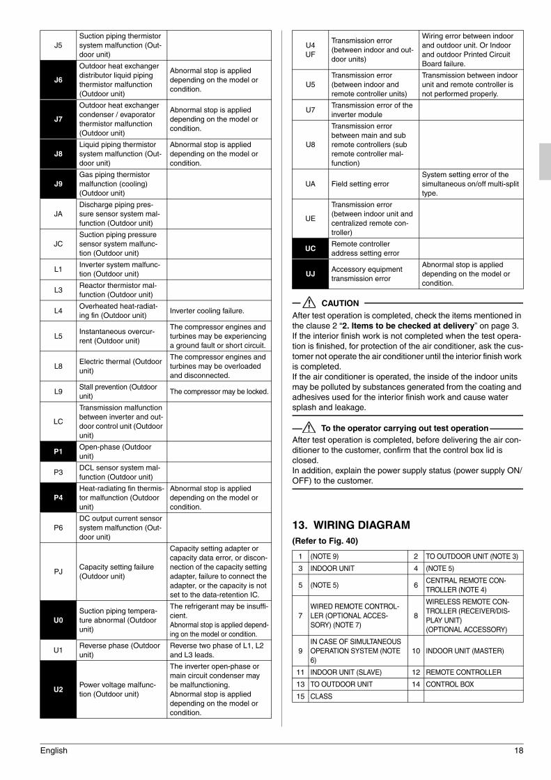
13. WIRING DIAGRAM
(Refer to Fig. 40)
J5
Suction piping thermistor
system malfunction (Out-
door unit)
J6
Outdoor heat exchanger
distributor liquid piping
thermistor malfunction
(Outdoor unit)
Abnormal stop is applied
depending on the model or
condition.
J7
Outdoor heat exchanger
condenser / evaporator
thermistor malfunction
(Outdoor unit)
Abnormal stop is applied
depending on the model or
condition.
J8
Liquid piping thermistor
system malfunction (Out-
door unit)
Abnormal stop is applied
depending on the model or
condition.
J9
Gas piping thermistor
malfunction (cooling)
(Outdoor unit)
JA
Discharge piping pres-
sure sensor system mal-
function (Outdoor unit)
JC
Suction piping pressure
sensor system malfunc-
tion (Outdoor unit)
L1Inverter system malfunc-
tion (Outdoor unit)
L3Reactor thermistor mal-
function (Outdoor unit)
L4Overheated heat-radiat-
ing fin (Outdoor unit)Inverter cooling failure.
L5Instantaneous overcur-
rent (Outdoor unit)
The compressor engines and
turbines may be experiencing
a ground fault or short circuit.
L8Electric thermal (Outdoor
unit)
The compressor engines and
turbines may be overloaded
and disconnected.
L9Stall prevention (Outdoor
unit)The compressor may be locked.
LC
Transmission malfunction
between inverter and out-
door control unit (Outdoor
unit)
P1Open-phase (Outdoor
unit)
P3DCL sensor system mal-
function (Outdoor unit)
P4
Heat-radiating fin thermis-
tor malfunction (Outdoor
unit)
Abnormal stop is applied
depending on the model or
condition.
P6
DC output current sensor
system malfunction (Out-
door unit)
PJCapacity setting failure
(Outdoor unit)
Capacity setting adapter or
capacity data error, or discon-
nection of the capacity setting
adapter, failure to connect the
adapter, or the capacity is not
set to the data-retention IC.
U0
Suction piping tempera-
ture abnormal (Outdoor
unit)
The refrigerant may be insuffi-
cient.
Abnormal stop is applied depend-
ing on the model or condition.
U1Reverse phase (Outdoor
unit)
Reverse two phase of L1, L2
and L3 leads.
U2Power voltage malfunc-
tion (Outdoor unit)
The inverter open-phase or
main circuit condenser may
be malfunctioning.
Abnormal stop is applied
depending on the model or
condition.
U4
UF
Transmission error
(between indoor and out-
door units)
Wiring error between indoor
and outdoor unit. Or Indoor
and outdoor Printed Circuit
Board failure.
U5
Transmission error
(between indoor and
remote controller units)
Transmission between indoor
unit and remote controller is
not performed properly.
U7Transmission error of the
inverter module
U8
Transmission error
between main and sub
remote controllers (sub
remote controller mal-
function)
UA Field setting error
System setting error of the
simultaneous on/off multi-split
type.
UE
Transmission error
(between indoor unit and
centralized remote con-
troller)
UCRemote controller
address setting error
UJAccessory equipment
transmission error
Abnormal stop is applied
depending on the model or
condition.
1 (NOTE 9) 2 TO OUTDOOR UNIT (NOTE 3)
3 INDOOR UNIT 4 (NOTE 5)
5 (NOTE 5) 6CENTRAL REMOTE CON-
TROLLER (NOTE 4)
7
WIRED REMOTE CONTROL-
LER (OPTIONAL ACCES-
SORY) (NOTE 7)
8
WIRELESS REMOTE CON-
TROLLER (RECEIVER/DIS-
PLAY UNIT)
(OPTIONAL ACCESSORY)
9
IN CASE OF SIMULTANEOUS
OPERATION SYSTEM (NOTE
6)
10 INDOOR UNIT (MASTER)
11 INDOOR UNIT (SLAVE) 12 REMOTE CONTROLLER
13 TO OUTDOOR UNIT 14 CONTROL BOX
15 CLASS
01_EN_3P368557-1.fm Page 18 Wednesday, December 10, 2014 10:31 AM
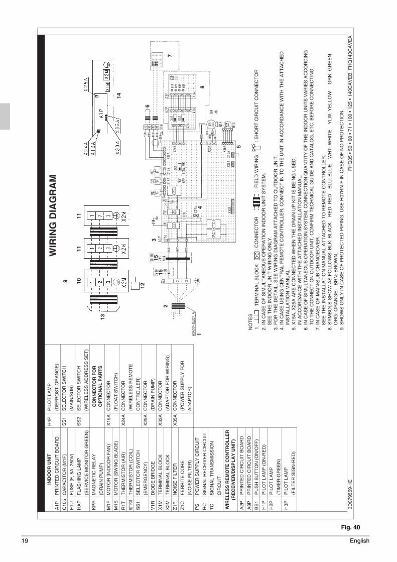
19 English
3D07
9559
-1E
FH
Q35
• 5
0 •
60 •
71
• 10
0 •
125
• 14
0CA
VE
B, F
HQ
140C
AV
EA
A1P
C10
5
F1U
HA
P
KP
R
M1F
M1S
R1T
R2T·R
3T
SS
1
V1R
X1M
X2M
Z1F
Z1C
PS
RC
TC A2P
A3P
BS
1
H1P
H2P
H3P
PR
INT
ED
CIR
CU
IT B
OA
RD
PR
INT
ED
CIR
CU
IT B
OA
RD
PU
SH
BU
TT
ON
(O
N/O
FF
)
PIL
OT
LA
MP
(O
N-R
ED
)
PIL
OT
LA
MP
(TIM
ER
-GR
EE
N)
PIL
OT
LA
MP
(FIL
TE
R S
IGN
-RE
D)
X15
A
X24
A
X25
A
X33
A
X35
A
CO
NN
EC
TO
R
(FLO
AT
SW
ITC
H)
CO
NN
EC
TO
R
(WIR
ELE
SS
RE
MO
TE
CO
NT
RO
LLE
R)
CO
NN
EC
TO
R
(DR
AIN
PU
MP
)
CO
NN
EC
TO
R
(AD
AP
TO
R F
OR
WIR
ING
)
CO
NN
EC
TO
R
(PO
WE
R S
UP
PLY
FO
R
AD
AP
TO
R)
PR
INT
ED
CIR
CU
IT B
OA
RD
CA
PA
CIT
OR
(M
1F)
FU
SE
(F
, 5A
, 250
V)
FLA
SH
ING
LA
MP
(SE
RV
ICE
MO
NIT
OR
GR
EE
N)
MA
GN
ET
IC R
ELA
Y
(DR
AIN
PU
MP
)
MO
TO
R (
IND
OO
R F
AN
)
MO
TO
R (
SW
ING
BLA
DE
)
TH
ER
MIS
TO
R (
AIR
)
TH
ER
MIS
TO
R (
CO
IL)
SE
LEC
TO
R S
WIT
CH
(EM
ER
GE
NC
Y)
DIO
DE
BR
IDG
E
TE
RM
INA
L B
LOC
K
TE
RM
INA
L B
LOC
K
NO
ISE
FIL
TE
R
FE
RR
ITE
CO
RE
(NO
ISE
FIL
TE
R)
PO
WE
R S
UP
PLY
CIR
CU
IT
SIG
NA
L R
EC
EIV
ER
CIR
CU
IT
SIG
NA
L T
RA
NS
MIS
SIO
N
CIR
CU
IT
2. IN
CA
SE
OF
SIM
ULT
AN
EO
US
OP
ER
AT
ION
IND
OO
R U
NIT
SY
ST
EM
.S
EE
TH
E IN
DO
OR
UN
IT W
IRIN
G O
NLY
.3.
FO
R T
HE
DE
TA
IL, S
EE
WIR
ING
DIA
GR
AM
AT
TA
CH
ED
TO
OU
TD
OO
R U
NIT
.4.
IN C
AS
E U
SIN
G C
EN
TR
AL
RE
MO
TE
CO
NT
RO
LLE
R, C
ON
NE
CT
IN T
O T
HE
UN
IT IN
AC
CO
RD
AN
CE
WIT
H T
HE
AT
TA
CH
ED
IN
ST
ALL
AT
ION
MA
NU
AL.
5. X
15A
, X25
A A
RE
CO
NN
EC
TE
D W
HE
N T
HE
DR
AIN
UP
KIT
IS B
EIN
G U
SE
D.
IN A
CC
OR
DA
NC
E W
ITH
TH
E A
TT
AC
HE
D IN
ST
ALL
AT
ION
MA
NU
AL.
6. IN
CA
SE
OF
SIM
ULT
AN
EO
US
OP
ER
AT
ION
SY
ST
EM
, CO
NN
EC
TIO
N Q
UA
NT
ITY
OF
TH
E IN
DO
OR
UN
ITS
VA
RIE
S A
CC
OR
DIN
G
TO
TH
E C
ON
NE
CT
ION
OU
TD
OO
R U
NIT
, CO
NF
IRM
TE
CH
NIC
AL
GU
IDE
AN
D C
AT
ALO
G, E
TC
. BE
FO
RE
CO
NN
EC
TIN
G.
7. IN
CA
SE
OF
MA
IN/S
UB
CH
AN
GE
OV
ER
.S
EE
TH
E IN
ST
ALL
AT
ION
MA
NU
AL
AT
TA
CH
ED
TO
RE
MO
TE
CO
NT
RO
LLE
R.
8. S
YM
BO
LS S
HO
W A
S F
OLL
OW
S: B
LK: B
LAC
K
RE
D: R
ED
B
LU: B
LUE
W
HT
: WH
ITE
Y
LW: Y
ELL
OW
G
RN
: GR
EE
NO
RG
: OR
AN
GE
B
RN
: BR
OW
N.
9. S
HO
WS
ON
LY IN
CA
SE
OF
PR
OT
EC
TE
D P
IPIN
G. U
SE
H07
RN
-F IN
CA
SE
OF
NO
PR
OT
EC
TIO
N.
IND
OO
R U
NIT
WIR
ELE
SS
RE
MO
TE C
ON
TRO
LLE
R(R
EC
EIV
ER
/DIS
PLA
Y U
NIT
)
CO
NN
EC
TOR
FO
RO
PTI
ON
AL
PA
RTS
H4P
SS
1
SS
2
PIL
OT
LA
MP
(DE
FR
OS
T-O
RA
NG
E)
SE
LEC
TO
R S
WIT
CH
(MA
IN/S
UB
)
SE
LEC
TO
R S
WIT
CH
(WIR
ELE
SS
AD
DR
ES
S S
ET
)
WIR
ING
DIA
GR
AM
: TE
RM
INA
L B
LOC
K1.N
OT
ES
: CO
NN
EC
TO
R:
FIE
LD W
IRIN
G: S
HO
RT
CIR
CU
IT C
ON
NE
CT
OR
14
13
109
1111
1
215
153
4
5
6
7
8
12
Fig. 40
01_EN_3P368557-1.fm Page 19 Wednesday, December 10, 2014 10:31 AM

(1502) HT3P368557-1 EM12A008D
00_CV_3P368557-1.fm Page 2 Wednesday, November 26, 2014 5:21 PM