INJECTOR SPECIFICATION - · PDF filepage 1 of 2 injector specification edition: 6 nozzle...
2
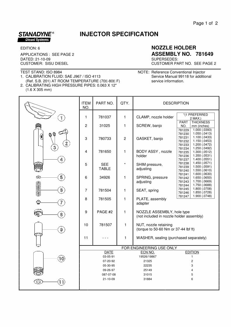
Page 1 of 2 INJECTOR SPECIFICATION EDITION: 6 NOZZLE HOLDER APPLICATIONS : SEE PAGE 2 ASSEMBLY NO. 781649 DATED: 21-10-09 SUPERSEDES: CUSTOMER: SISU DIESEL CUSTOMER PART NO. SEE PAGE 2 TEST STAND: ISO 8984 NOTE: Reference Conventional Injector 1. CALIBRATION FLUID: SAE J967 / ISO 4113 Service Manual 99118 for additional (Ref. S.B. 201) AT ROOM TEMPERATURE (70Ε-80Ε F) service information. 2. CALIBRATING HIGH PRESSURE PIPES: 0.063 X 12" (1.6 X 305 mm) ITEM NO. PART NO. QTY. DESCRIPTION 1 2 3 4 5 6 7 8 9 10 11 781037 31025 780733 781650 SEE TABLE 34926 781504 781505 PAGE #2 781507 - - - 1 1 2 1 * 1 1 1 1 1 1 CLAMP, nozzle holder SCREW, banjo GASKET, banjo BODY ASSY , nozzle holder SHIM pressure, adjusting SPRING, pressure adjusting SEAT, spring PLATE, assembly adapter NOZZLE ASSEMBLY, hole type (not included in nozzle holder assembly) NUT, nozzle retaining (torque to 50-60 Nm or 37-44 lbf ft) WASHER, sealing (purchased separately) FOR ENGINEERING USE ONLY DATE ECN NO. EDITION 03-05-91 19526/19867 1 07-20-92 21325 2 05-30-95 22235 3 09-26-97 25149 4 087-07-08 31015 5 21-10-09 31884 6 *(1 PREFERRED 2 MAX.) PART NO. THICKNESS mm (inches) 781229 781230 781231 781232 781233 781234 781235 781236 781237 781238 781239 781240 781241 781242 781243 781244 781245 781246 781247 1.000 (.0393) 1.050 (.0413) 1.100 (.0433) 1.150 (.0453) 1.200 (.0472) 1.250 (.0492) 1.300 (.0512) 1.350 (.0531) 1.400 (.0551) 1.450 (.0571) 1.500 (.0591) 1.550 (.0610) 1.600 (.0630) 1.650 (.0650) 1.700 (.0669) 1.750 (.0688) 1.800 (.0708) 1.850 (.0728) 1.900 (.0748)
Transcript of INJECTOR SPECIFICATION - · PDF filepage 1 of 2 injector specification edition: 6 nozzle...
Page 1 of 2
INJECTOR SPECIFICATION
EDITION: 6 NOZZLE HOLDER
APPLICATIONS : SEE PAGE 2 ASSEMBLY NO. 781649 DATED: 21-10-09 SUPERSEDES: CUSTOMER: SISU DIESEL CUSTOMER PART NO. SEE PAGE 2 TEST STAND: ISO 8984 NOTE: Reference Conventional Injector 1. CALIBRATION FLUID: SAE J967 / ISO 4113 Service Manual 99118 for additional
(Ref. S.B. 201) AT ROOM TEMPERATURE (70Ε-80Ε F) service information. 2. CALIBRATING HIGH PRESSURE PIPES: 0.063 X 12" (1.6 X 305 mm)
ITEM NO.
PART NO.
QTY.
DESCRIPTION
1 2 3 4 5 6 7 8 9
10 11
781037
31025
780733
781650
SEE TABLE
34926
781504
781505
PAGE #2 781507 - - -
1
1
2
1 *
1
1
1
1
1 1
CLAMP, nozzle holder SCREW, banjo GASKET, banjo BODY ASSY , nozzle holder SHIM pressure, adjusting SPRING, pressure adjusting SEAT, spring PLATE, assembly adapter NOZZLE ASSEMBLY, hole type (not included in nozzle holder assembly) NUT, nozzle retaining (torque to 50-60 Nm or 37-44 lbf ft) WASHER, sealing (purchased separately)
FOR ENGINEERING USE ONLY DATE ECN NO. EDITION
03-05-91 19526/19867 1
07-20-92 21325 2
05-30-95 22235 3
09-26-97 25149 4
087-07-08 31015 5
21-10-09 31884 6
*(1 PREFERRED 2 MAX.)
PART NO.
THICKNESS mm (inches)
781229 781230 781231 781232 781233 781234 781235 781236 781237 781238 781239 781240 781241 781242 781243 781244 781245 781246 781247
1.000 (.0393) 1.050 (.0413) 1.100 (.0433) 1.150 (.0453) 1.200 (.0472) 1.250 (.0492) 1.300 (.0512) 1.350 (.0531) 1.400 (.0551) 1.450 (.0571) 1.500 (.0591) 1.550 (.0610) 1.600 (.0630) 1.650 (.0650) 1.700 (.0669) 1.750 (.0688) 1.800 (.0708) 1.850 (.0728) 1.900 (.0748)
Page 2 of 2
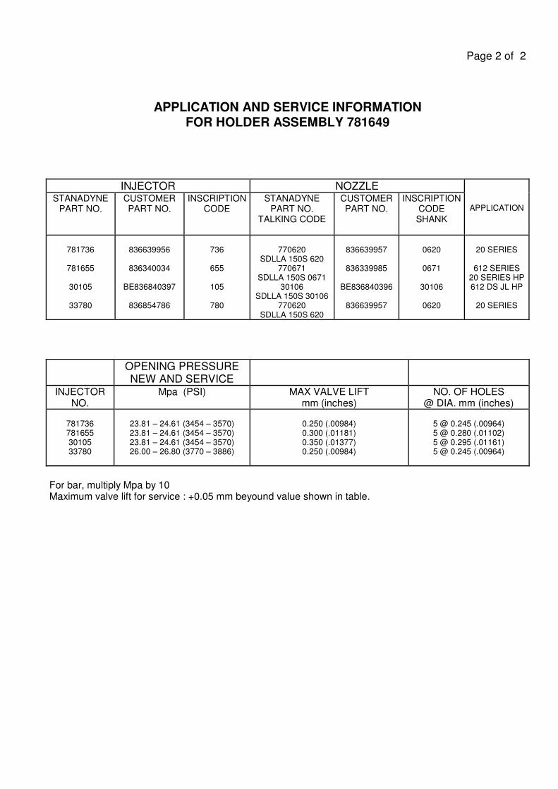
APPLICATION AND SERVICE INFORMATION
FOR HOLDER ASSEMBLY 781649
INJECTOR NOZZLE
APPLICATION STANADYNE
PART NO.
CUSTOMER PART NO.
INSCRIPTION CODE
STANADYNE PART NO.
TALKING CODE
CUSTOMER PART NO.
INSCRIPTION CODE SHANK
781736
781655
30105
33780
836639956
836340034
BE836840397
836854786
736
655
105
780
770620
SDLLA 150S 620 770671
SDLLA 150S 0671 30106
SDLLA 150S 30106 770620
SDLLA 150S 620
836639957
836339985
BE836840396
836639957
0620
0671
30106
0620
20 SERIES
612 SERIES
20 SERIES HP 612 DS JL HP
20 SERIES
OPENING PRESSURE NEW AND SERVICE
INJECTOR NO.
Mpa (PSI) MAX VALVE LIFT mm (inches)
NO. OF HOLES @ DIA. mm (inches)
781736 781655 30105 33780
23.81 – 24.61 (3454 – 3570) 23.81 – 24.61 (3454 – 3570) 23.81 – 24.61 (3454 – 3570) 26.00 – 26.80 (3770 – 3886)
0.250 (.00984) 0.300 (.01181) 0.350 (.01377) 0.250 (.00984)
5 @ 0.245 (.00964) 5 @ 0.280 (.01102) 5 @ 0.295 (.01161) 5 @ 0.245 (.00964)
For bar, multiply Mpa by 10 Maximum valve lift for service : +0.05 mm beyound value shown in table.