Injection Locked Oscillators Optoelectronic Applications E. Shumakher, J. Lasri, B. Sheinman, G....
33
Injection Locked Injection Locked Oscillators Oscillators Optoelectronic Optoelectronic Applications Applications E. Shumakher, J. Lasri, B. Sheinman, G. Eisenstein, E. Shumakher, J. Lasri, B. Sheinman, G. Eisenstein, D. Ritter D. Ritter Electrical Engineering Dept. TECHNION Electrical Engineering Dept. TECHNION Haifa ISRAEL Haifa ISRAEL Q 1, ω 1 Q 2, ω 2
-
Upload
jade-holland -
Category
Documents
-
view
215 -
download
0
Transcript of Injection Locked Oscillators Optoelectronic Applications E. Shumakher, J. Lasri, B. Sheinman, G....
Injection Locked Oscillators Injection Locked Oscillators Optoelectronic ApplicationsOptoelectronic Applications
E. Shumakher, J. Lasri, B. Sheinman, G. Eisenstein, D. RitterE. Shumakher, J. Lasri, B. Sheinman, G. Eisenstein, D. RitterElectrical Engineering Dept. TECHNIONElectrical Engineering Dept. TECHNION
Haifa ISRAELHaifa ISRAEL
Q1, ω1 Q2, ω2
1 1Q
Non-LinearGain
satV iVrV
BPF
nsV
nsV
2112 Non-Linear
Gain
satViV
rV
Delay Line
Delay Line
2
BPF
2Q
tx2
12 n
tx1
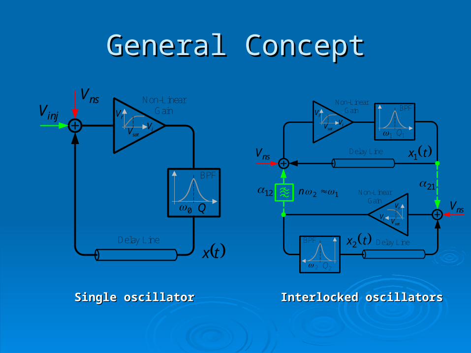
General ConceptGeneral Concept
Delay Line
nsV Non-LinearGain
tx
injVsatV iV
rV
0
BPF
Q
Single oscillatorSingle oscillator Interlocked oscillatorsInterlocked oscillators
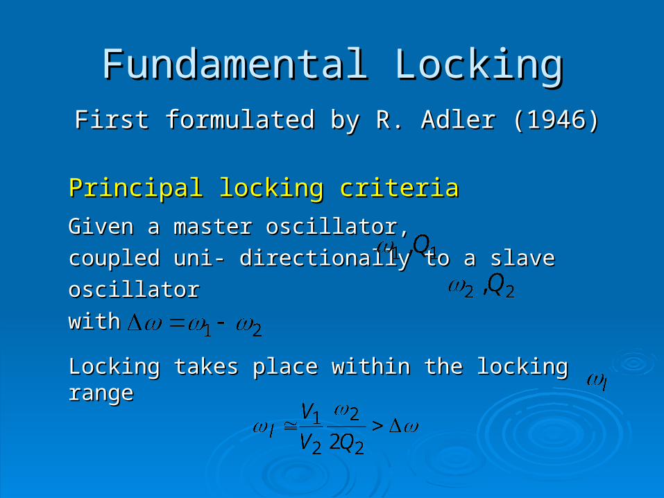
Fundamental LockingFundamental Locking First formulated by R. Adler (1946)First formulated by R. Adler (1946)
Principal locking criteriaPrincipal locking criteria
Given a master oscillator,Given a master oscillator, coupled uni- coupled uni-
directionally to a slave oscillator directionally to a slave oscillator
withwith
Locking takes place within the locking rangeLocking takes place within the locking range
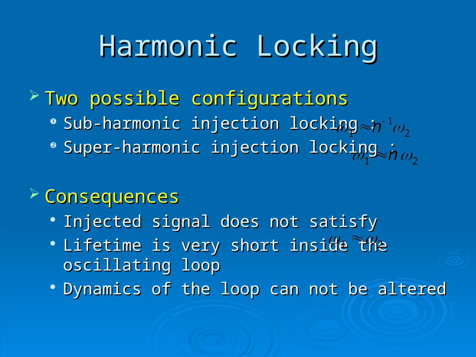
Harmonic LockingHarmonic Locking
Two possible configurationsTwo possible configurations Sub-harmonic injection locking :Sub-harmonic injection locking : Super-harmonic injection locking :Super-harmonic injection locking :
ConsequencesConsequences Injected signal does not satisfyInjected signal does not satisfy Lifetime is very short inside the oscillating loopLifetime is very short inside the oscillating loop Dynamics of the loop can not be alteredDynamics of the loop can not be altered
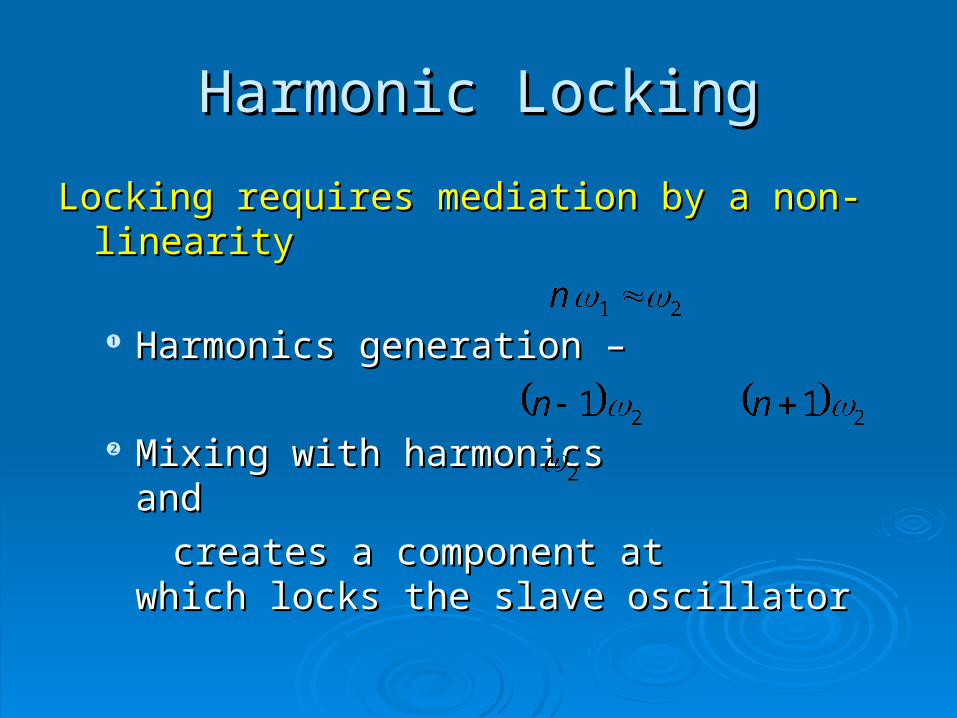
Locking requires mediation by a non-linearityLocking requires mediation by a non-linearity
Harmonics generation –Harmonics generation –
Mixing with harmonicsMixing with harmonics and and
creates a component at which locks the creates a component at which locks the slave oscillatorslave oscillator
Harmonic LockingHarmonic Locking
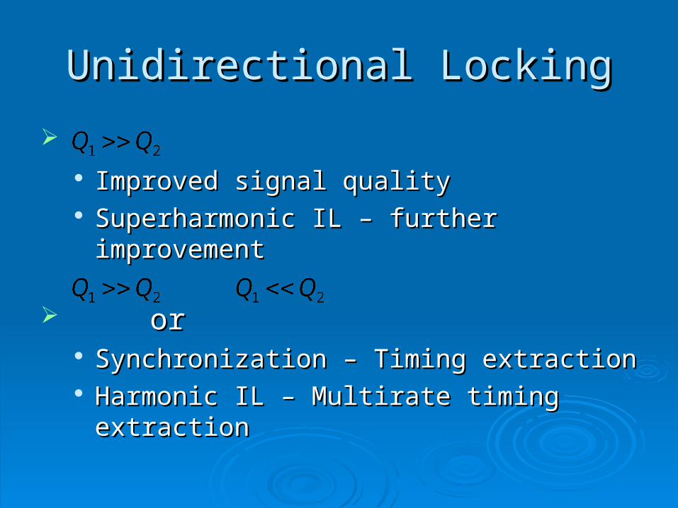
Unidirectional LockingUnidirectional Locking
Improved signal qualityImproved signal quality Superharmonic IL – further improvementSuperharmonic IL – further improvement
or or Synchronization – Timing extractionSynchronization – Timing extraction Harmonic IL – Multirate timing extractionHarmonic IL – Multirate timing extraction
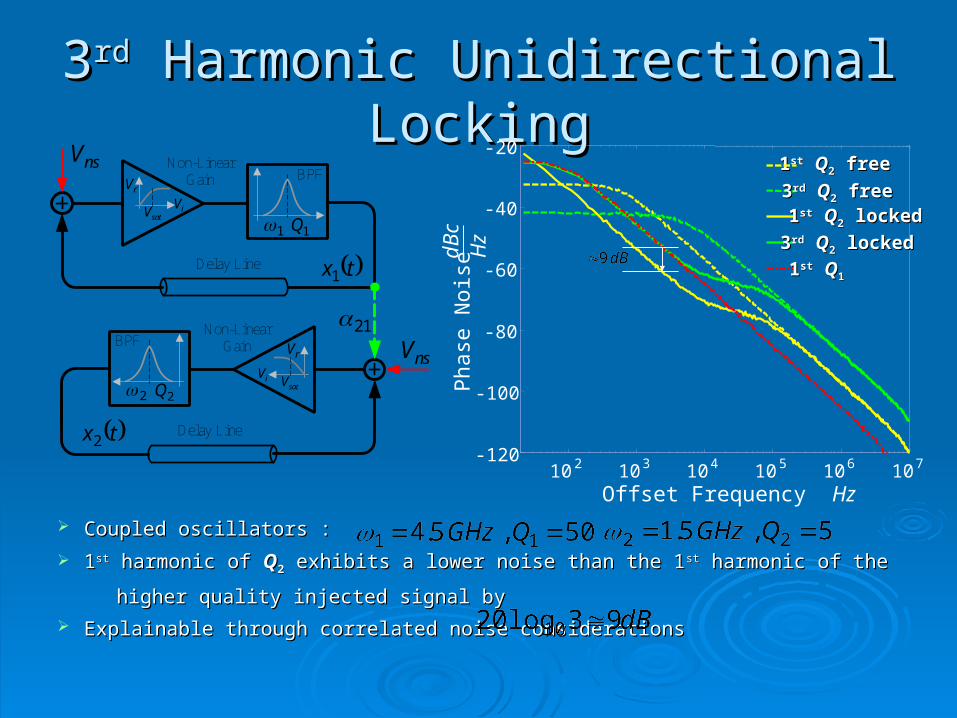
33rdrd Harmonic Unidirectional Locking Harmonic Unidirectional Locking
Coupled oscillators : Coupled oscillators :
11stst harmonic of harmonic of QQ22 exhibits a lower noise than the 1 exhibits a lower noise than the 1stst harmonic of the harmonic of the
higher quality injected signal byhigher quality injected signal by
Explainable through correlated noise considerationsExplainable through correlated noise considerations
10 2 10 3 10 4 10 5 10 6 10 7-120
-100
-80
-60
-40
-20 11stst QQ22 free free
33rdrd QQ22 free free 11stst QQ22 locked locked
33rdrd QQ22 locked locked
11stst QQ11Delay Line
nsV Non-LinearGain
tx1
satV iVrV
1
BPF
1Q
Delay Line
nsVNon-Linear
Gain
tx2
satViV
rV
2
BPF
2Q
21
Offset Frequency Hz
Pha
se N
oise
dBc
Hz
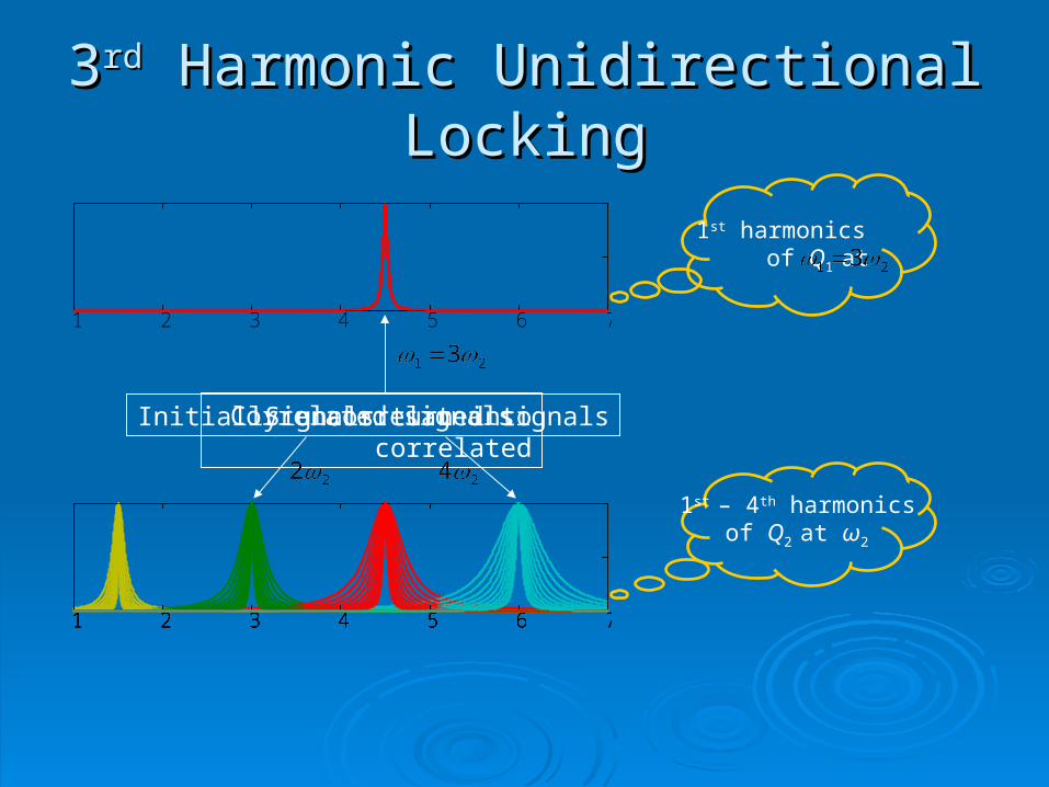
33rdrd Harmonic Unidirectional Locking Harmonic Unidirectional Locking
1 2 3 4 5 6 71 2 3 4 5 6 71 2 3 4 5 6 71 2 3 4 5 6 71 2 3 4 5 6 71 2 3 4 5 6 71 2 3 4 5 6 71 2 3 4 5 6 71 2 3 4 5 6 71 2 3 4 5 6 7
1 2 3 4 5 6 7
Initially uncorrelated signalsSignals turn into correlatedCorrelated signals
1st harmonics of Q1 at
1st – 4th harmonics of Q2 at ω2
1 2 3 4 5 6 7
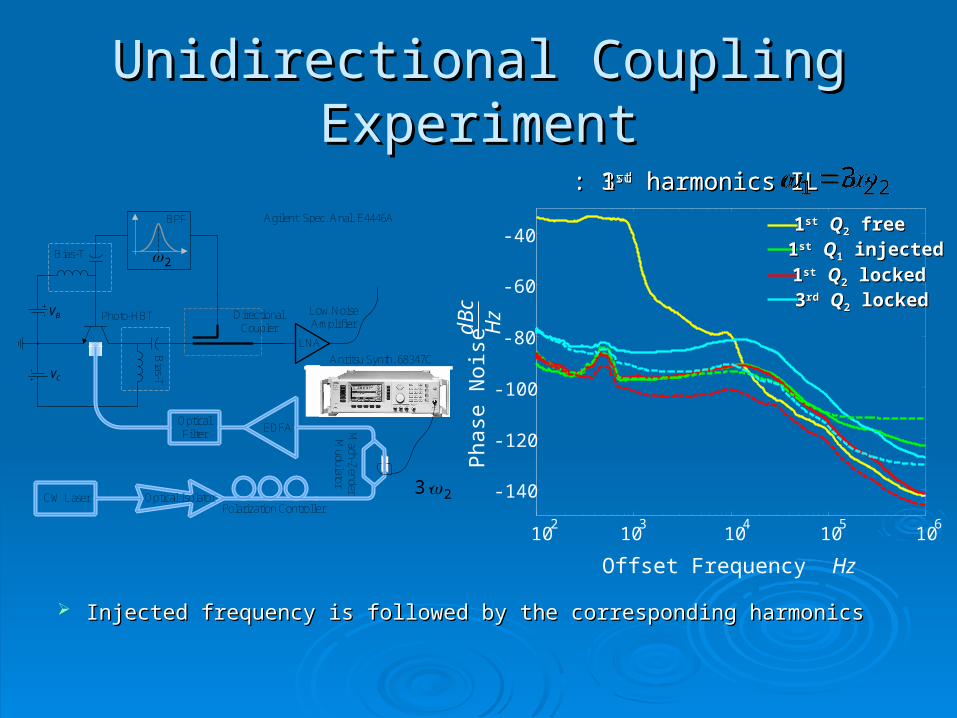
Unidirectional Coupling ExperimentUnidirectional Coupling Experiment
Injected frequency is followed by the corresponding harmonicsInjected frequency is followed by the corresponding harmonics
Bias-T
Bias-TCV
DirectionalCoupler
Agilent Spec. Anal. E4446ABPF
Photo-HBT
EDFA
LNA
OpticalFilter
BV Low NoiseAmplifier
CW Laser Optical IsolatorPolarization Controller
Anritsu Synth. 68347C
Mach-Z
enderM
udulator
2
102
106
103
104
105
-140
-120
-100
-80
-60
-40 11stst QQ22 free free 11stst QQ11 injected injected 11stst QQ22 locked locked 33rdrd QQ22 locked locked
23
Offset Frequency Hz
Pha
se N
oise
dBc
Hz
33rdrd harmonics IL harmonics IL: : 11stst harmonics IL harmonics IL: :
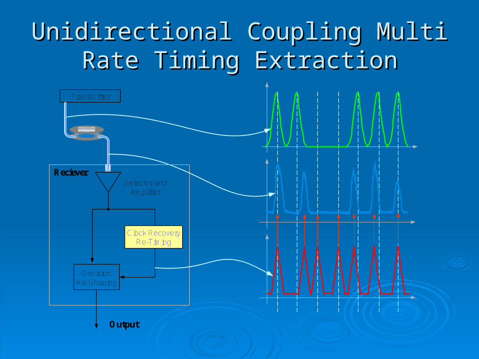
Unidirectional Coupling Multi Rate Unidirectional Coupling Multi Rate Timing ExtractionTiming Extraction
Transmitter
Detector andAmplifier
Clock RecoveryRe-Timing
DecisionRe-Shaping
Output
Reciever
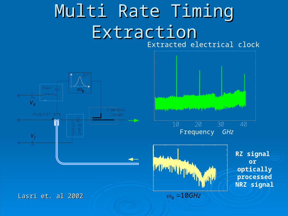
Multi Rate Timing ExtractionMulti Rate Timing Extraction
10 20 30 40
BV
Bias-T
Bias-T
CV
DirectionalCoupler
0
BPF
Photo-HBT
Frequency GHz
RZ signal or
optically processed NRZ
signal
GHz100
Extracted electrical clock
Lasri et. al 2002Lasri et. al 2002
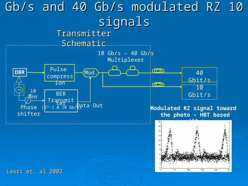
Modulated RZ signal toward the photo – HBT based oscillator
Transmitter SchematicTransmitter Schematic
10 Gb/s – 40 Gb/sMultiplexer
Mod.
Data OutPhase shifter
DBR
~
Pulse compression
BERTransmitter
(231-1 @ 10 Gb/s)
40 Gbit/s
10 Gbit/s10 GHz
1010 Gb/s and 40 Gb/s modulated RZ signalsGb/s and 40 Gb/s modulated RZ signals
Lasri et. al 2002Lasri et. al 2002
BV
Bias-T
Bia
s-T CV
DirectionalCoupler
Photo-HBT
0
BPF
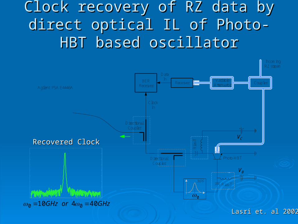
Agilent PSA E4446A
DirectionalCoupler
CouplerVariable
Attenuator
IncomingRZ stream
ReceiverBERReceiver
DataIn
ClockIn
Recovered ClockRecovered Clock
Clock recovery of RZ data by direct Clock recovery of RZ data by direct optical IL of Photo-HBT based oscillatoroptical IL of Photo-HBT based oscillator
GHzorGHz 40410 00 Lasri et. al 2002Lasri et. al 2002
Det
ecte
d P
ower
dB
m
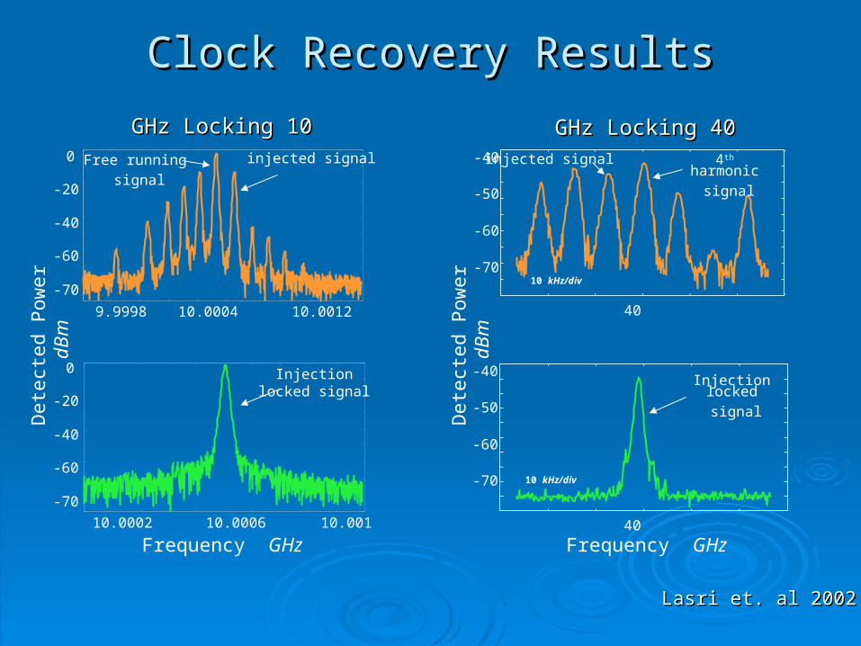
9.9998 10.0004 10.0012
-70
-60
-40
-20
0 injected signal
10.0002 10.0006 10.001
Free running
signal
Injection locked signal
-70
-60
-40
-20
0
4th harmonic
signal
injected signal
Injection locked
signal
-70
-60
-50
-40
-70
-60
-50
-40
10 kHz/div
40
40
1010 GHz LockingGHz Locking
Frequency GHz
Clock Recovery ResultsClock Recovery Results
4040 GHz LockingGHz Locking
Frequency GHz
Det
ecte
d P
ower
dB
m10 kHz/div
Lasri et. al 2002Lasri et. al 2002
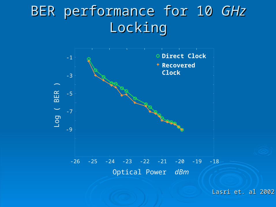
-26 -25 -24 -23 -22 -21 -20 -19 -18
-9
-7
-5
-3
-1
Optical Power dBm
Log
( B
ER
)Direct Clock
Recovered Clock
BER performance for 10 BER performance for 10 GHzGHz Locking Locking
Lasri et. al 2002Lasri et. al 2002
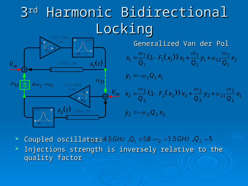
33rdrd Harmonic Bidirectional Locking Harmonic Bidirectional Locking
Coupled oscillators :Coupled oscillators : Injections strength is inversely relative to the quality factorInjections strength is inversely relative to the quality factor
1 1Q
Non-LinearGain
satV iVrV
BPF
nsV
nsV
2112 Non-Linear
Gain
satViV
rV
Delay Line
Delay Line
2
BPF
2Q
tx2
12 n
tx1
21
1121
1
1111
1
11 1 x
Qy
QxxF
Qx
1111 xQy
12
2212
2
2222
2
22 1 x
Qy
QxxF
Qx
2222 xQy
Generalized Van der PolGeneralized Van der Pol
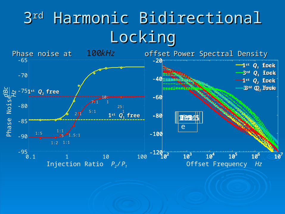
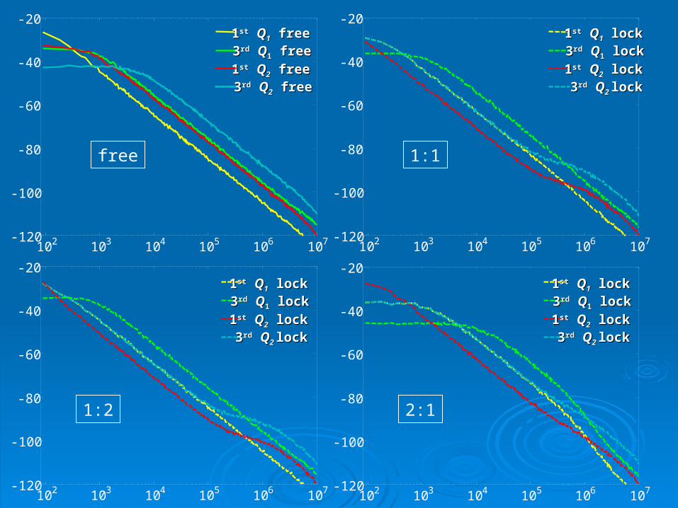
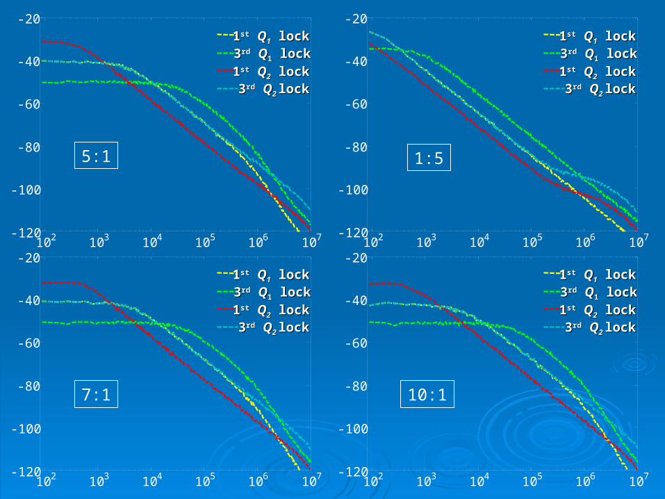
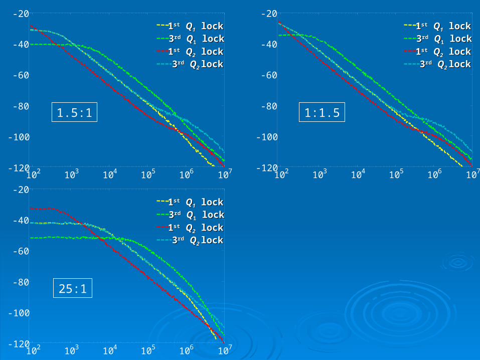
33rdrd Harmonic Bidirectional Locking Harmonic Bidirectional Locking
0.1 1 10 100-95
-90
-85
-80
-75
-70
-65
Injection Ratio P2 / P1
Pha
se N
oise
dBc
Hz 11stst QQ2 2 freefree
11stst QQ1 1 freefree
25:125:1
10:110:1
7:17:1 5:15:1 2:12:1
1.5:11.5:1
1:11:1
1:1.51:1.5
1:21:2
1:51:5
102 103 104 105 106 107-120
-100
-80
-60
-40
-20 11stst QQ11 free free 33rdrd QQ11 free free
11stst QQ22 free free 33rdrd QQ22 free free
free
102 103 104 105 106 107-120
-100
-80
-60
-40
-20 11stst QQ11 lock lock 33rdrd QQ11 lock lock
11stst QQ22 lock lock 33rdrd QQ2 2 locklock
1:51:2
102 103 104 105 106 107-120
-100
-80
-60
-40
-20
102 103 104 105 106 107-120
-100
-80
-60
-40
-20
1:1.5
102 103 104 105 106 107-120
-100
-80
-60
-40
-20
1:11.5:1
102 103 104 105 106 107-120
-100
-80
-60
-40
-20
102 103 104 105 106 107-120
-100
-80
-60
-40
-20
2:1
102 103 104 105 106 107-120
-100
-80
-60
-40
-20
5:1
102 103 104 105 106 107-120
-100
-80
-60
-40
-20
7:1
102 103 104 105 106 107-120
-100
-80
-60
-40
-20
10:1
102 103 104 105 106 107-120
-100
-80
-60
-40
-20
25:1
Offset Frequency Hz
Phase noise at offsetPhase noise at offset Power Spectral DensityPower Spectral Density
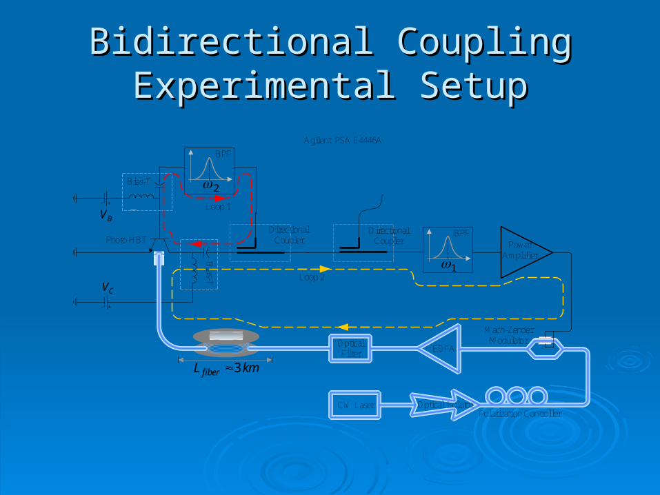
Bidirectional CouplingBidirectional CouplingExperimental SetupExperimental Setup
EDFA
PowerAmplifier
BV
Bias-T
Bias-T
CV
DirectionalCoupler
Agilent PSA E4446A
DirectionalCoupler
2
BPF
1
BPF
kmL fiber 3
Photo-HBT
Loop 1
Loop 2
OpticalFilter
CW Laser Optical IsolatorPolarization Controller
Mach-ZenderModulator
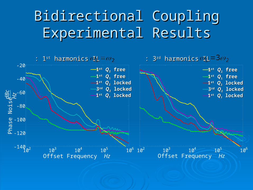
Bidirectional CouplingBidirectional CouplingExperimental ResultsExperimental Results
102 103 104 105 106-140
-120
-100
-80
-60
-40
-20 11stst QQ22 free free
11stst QQ11 free free
11stst QQ11 locked locked 33rdrd QQ22 locked locked 11stst QQ22 locked locked
102 103 104 105 106
11stst QQ22 free free 11stst QQ11 free free
11stst QQ11 locked locked 33rdrd QQ22 locked locked 11stst QQ22 locked locked
Offset Frequency Hz
Pha
se N
oise
dBc
Hz
Offset Frequency Hz
33rdrd harmonics IL harmonics IL: : 11stst harmonics IL harmonics IL: :
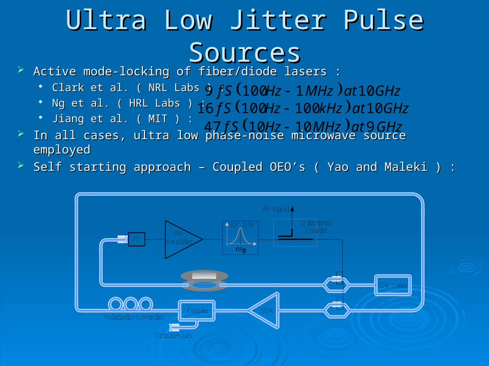
Ultra Low Jitter Pulse SourcesUltra Low Jitter Pulse Sources
RFAmplifier
0
RF BPF
CW Laser
DirectionalCoupler
PD
RF Signal
SOAPolarization Controller
Coupler
Optical Pulses
Active mode-locking of fiber/diode lasers :Active mode-locking of fiber/diode lasers : Clark et al. ( NRL Labs ) : Clark et al. ( NRL Labs ) : Ng et al. ( HRL Labs ) : Ng et al. ( HRL Labs ) : Jiang et al. ( MIT ) :Jiang et al. ( MIT ) :
In all cases, ultra low phase-noise microwave source employedIn all cases, ultra low phase-noise microwave source employed Self starting approach – Coupled OEO’s ( Yao and Maleki ) :Self starting approach – Coupled OEO’s ( Yao and Maleki ) :
GHzatMHzHzSf 1011009 GHzatkHzHzSf 1010010016 GHzatMHzHzSf 9101047
PowerAmplifier
DCI
Bias-T
Laser Diode
AR
laserL
FBG
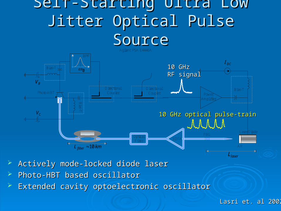
Lasri et. al 2002Lasri et. al 2002
kmL fiber 10
OpticalFilter
EDFA
Self-Starting Ultra Low Jitter Optical Self-Starting Ultra Low Jitter Optical Pulse SourcePulse Source
10 GHz 10 GHz RF signalRF signal
10 GHz optical pulse-train10 GHz optical pulse-train
BV
Bias-T
Bias-T
CV
DirectionalCoupler
Agilent PSA E4446A
DirectionalCoupler
0
BPF
Photo-HBT
Actively mode-locked diode laserActively mode-locked diode laser Photo-HBT based oscillatorPhoto-HBT based oscillator Extended cavity optoelectronic oscillatorExtended cavity optoelectronic oscillator
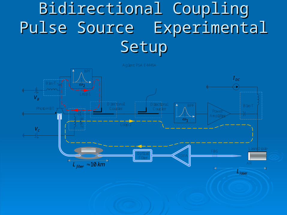
Bidirectional Coupling Pulse Source Bidirectional Coupling Pulse Source Experimental Setup Experimental Setup
PowerAmplifier
BV
Bias-T
Bias-T
CV
DirectionalCoupler
Agilent PSA E4446A
DirectionalCoupler
2
BPF
1
BPF
kmL fiber 10
Photo-HBT
Loop 1
Loop 2
OpticalFilter
DCI
Bias-T
Laser Diode
AR
laserL
FBGEDFA
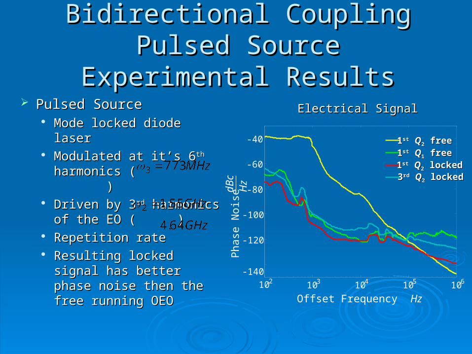
Bidirectional Coupling Pulsed SourceBidirectional Coupling Pulsed SourceExperimental ResultsExperimental Results
Pulsed SourcePulsed Source Mode locked diode laserMode locked diode laser Modulated at it’s 6Modulated at it’s 6thth
harmonics ( )harmonics ( ) Driven by 3Driven by 3rdrd harmonics harmonics
of the EO ( of the EO ( ) ) Repetition rateRepetition rate Resulting locked signal Resulting locked signal
has better phase noise has better phase noise then the free running then the free running OEO OEO
-140
102 103 104 105 106
-120
-100
-80
-60
-40 11stst QQ22 free free 11stst QQ11 free free 11stst QQ22 locked locked 33rdrd QQ22 locked locked
Offset Frequency Hz
Pha
se N
oise
dBc
Hz
Electrical SignalElectrical Signal
10 GHz5 kHz/div
Pow
er d
Bm
-85
-75
-65
-55
-45
-35
-25
-15
-5
Closed loop
Open loop
0.05
0.15
0.25
0.35
1542.5 1543 1543.5 1544 1544.5
0.05
0.15
0.25
0.35
Wavelength nm
Open Loop
Closed Loop
1543.51542.5 1543 1544 1544.5
Pow
er m
W
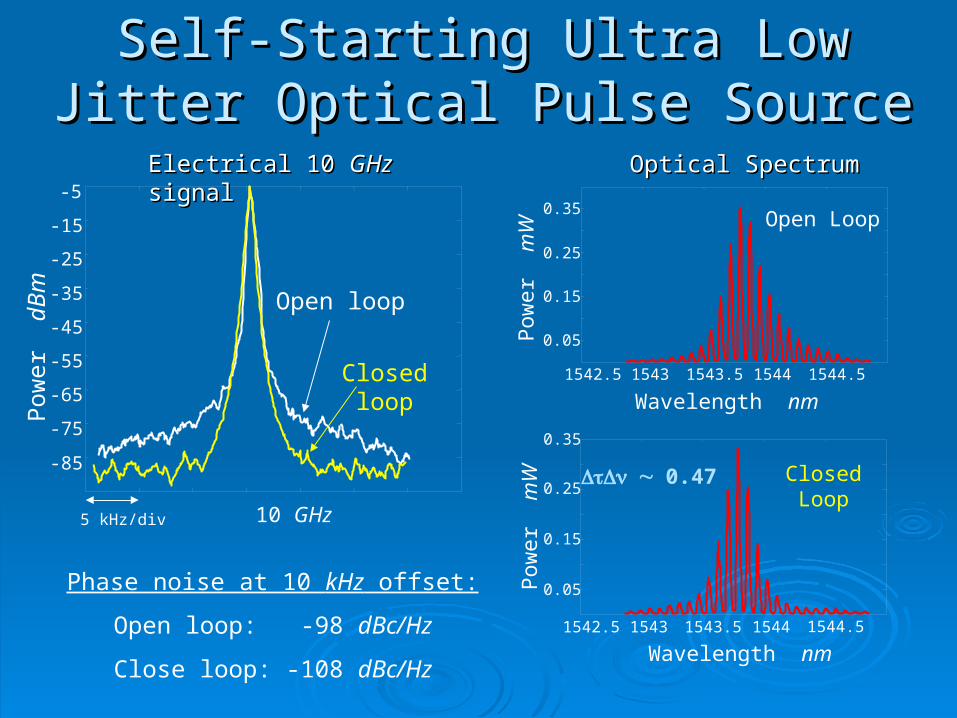
Phase noise at 10 kHz offset:
Open loop: -98 dBc/Hz
Close loop: -108 dBc/Hz
Electrical 10 Electrical 10 GHzGHz signal signal
0.47
Pow
er m
W
Wavelength nm
Optical SpectrumOptical Spectrum
Self-Starting Ultra Low Jitter Optical Self-Starting Ultra Low Jitter Optical Pulse SourcePulse Source
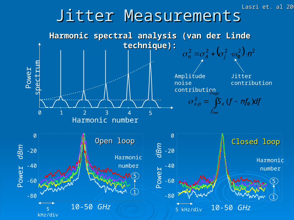
Harmonic spectral analysis (van der Linde technique):Harmonic spectral analysis (van der Linde technique):
0 1 2 3 4 5Harmonic number
Pow
er s
pect
rum 22
0222 nJAn
Amplitude noise contribution
Jitter contribution
high
low
f
f
xnx dfnffS )( 02,
-80
-60
-40
-20
0
10-50 GHz5 kHz/div
Pow
er d
Bm
1
5
Harmonic
number
Open loopOpen loop
Pow
er d
Bm
-80
-60
-40
-20
0
10-50 GHz5 kHz/div
Closed loopClosed loop
1
5
Harmonic
number
Lasri et. al 2002Lasri et. al 2002
Jitter MeasurementsJitter Measurements
10 10 10 10 102 3 4 5 6
-120
-100
-80
-60
1
4
Harmonic
number
Closed Loop
0 1 2 3 4 50
0.05
0.1
0.15
0.2
0.25
0.3
0.35
Harmonic Number
RM
S N
oise
mW
100 Hz – 1 MHz
500 Hz – 1 MHz
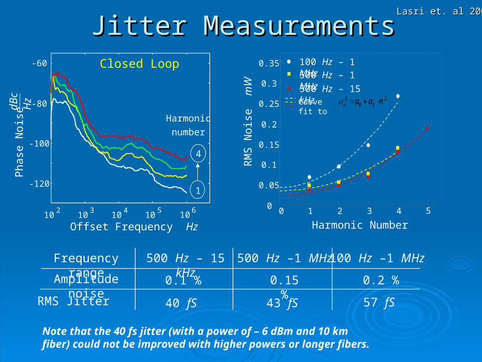
500 Hz – 15 kHzCurve fit to 2
202 naan
Frequency range
Amplitude noise
RMS Jitter
500 Hz – 15 kHz 500 Hz –1 MHz 100 Hz –1 MHz
0.1 % 0.15 % 0.2 %
40 fS 43 fS 57 fS
Note that the 40 fs jitter (with a power of – 6 dBm and 10 km fiber) could not be improved with higher powers or longer fibers.
Pha
se N
oise
dBc
Hz
Offset Frequency Hz
Lasri et. al 2002Lasri et. al 2002
Jitter MeasurementsJitter Measurements
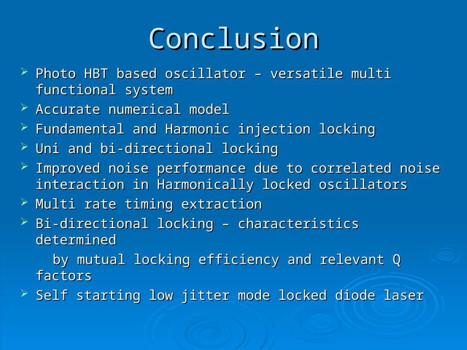
ConclusionConclusion Photo HBT based oscillator – versatile multi functional Photo HBT based oscillator – versatile multi functional
systemsystem Accurate numerical modelAccurate numerical model Fundamental and Harmonic injection lockingFundamental and Harmonic injection locking Uni and bi-directional locking Uni and bi-directional locking Improved noise performance due to correlated noise Improved noise performance due to correlated noise
interaction in Harmonically locked oscillatorsinteraction in Harmonically locked oscillators Multi rate timing extractionMulti rate timing extraction Bi-directional locking – characteristics determinedBi-directional locking – characteristics determined
by mutual locking efficiency and relevant Q factorsby mutual locking efficiency and relevant Q factors Self starting low jitter mode locked diode laserSelf starting low jitter mode locked diode laser
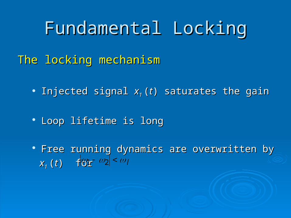
The locking mechanismThe locking mechanism
Injected signal Injected signal xx1 1 ((tt)) saturates the gain saturates the gain
Loop lifetime is long Loop lifetime is long
Free running dynamics are overwritten by Free running dynamics are overwritten by
xx1 1 ((tt) for ) for
Fundamental LockingFundamental Locking
11stst QQ11 lock lock 33rdrd QQ11 lock lock 11stst QQ22 lock lock 33rdrd QQ2 2 locklock
102 103 104 105 106 107-120
-100
-80
-60
-40
-20
1:1
11stst QQ11 lock lock 33rdrd QQ11 lock lock 11stst QQ22 lock lock 33rdrd QQ2 2 locklock
1:2
102 103 104 105 106 107-120
-100
-80
-60
-40
-20
102 103 104 105 106 107-120
-100
-80
-60
-40
-20 11stst QQ11 lock lock 33rdrd QQ11 lock lock 11stst QQ22 lock lock 33rdrd QQ2 2 locklock
2:1
102 103 104 105 106 107-120
-100
-80
-60
-40
-20 11stst QQ11 free free 33rdrd QQ11 free free 11stst QQ22 free free 33rdrd QQ22 free free
free
102 103 104 105 106 107-120
-100
-80
-60
-40
-20 11stst QQ11 lock lock 33rdrd QQ11 lock lock
11stst QQ22 lock lock 33rdrd QQ2 2 locklock
5:1
102 103 104 105 106 107-120
-100
-80
-60
-40
-20 11stst QQ11 lock lock 33rdrd QQ11 lock lock 11stst QQ22 lock lock 33rdrd QQ2 2 locklock
7:1
102 103 104 105 106 107-120
-100
-80
-60
-40
-20 11stst QQ11 lock lock 33rdrd QQ11 lock lock 11stst QQ22 lock lock 33rdrd QQ2 2 locklock
10:1
102 103 104 105 106 107-120
-100
-80
-60
-40
-20 11stst QQ11 lock lock 33rdrd QQ11 lock lock
11stst QQ22 lock lock 33rdrd QQ2 2 locklock
1:5
11stst QQ11 lock lock 33rdrd QQ11 lock lock
11stst QQ22 lock lock 33rdrd QQ2 2 locklock
1.5:1
102 103 104 105 106 107-120
-100
-80
-60
-40
-20
102 103 104 105 106 107-120
-100
-80
-60
-40
-20 11stst QQ11 lock lock 33rdrd QQ11 lock lock
11stst QQ22 lock lock 33rdrd QQ2 2 locklock
1:1.5
102 103 104 105 106 107-120
-100
-80
-60
-40
-20 11stst QQ11 lock lock 33rdrd QQ11 lock lock 11stst QQ22 lock lock 33rdrd QQ2 2 locklock
25:1
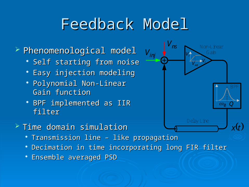
Feedback ModelFeedback Model
Phenomenological modelPhenomenological model Self starting from noiseSelf starting from noise Easy injection modelingEasy injection modeling Polynomial Non-Linear Gain Polynomial Non-Linear Gain
functionfunction BPF implemented as IIR filterBPF implemented as IIR filter
Delay Line
nsV Non-LinearGain
tx
injVsatV iV
rV
0
BPF
Q
Time domain simulationTime domain simulation Transmission line – like propagationTransmission line – like propagation Decimation in time incorporating long FIR filterDecimation in time incorporating long FIR filter Ensemble averaged PSDEnsemble averaged PSD
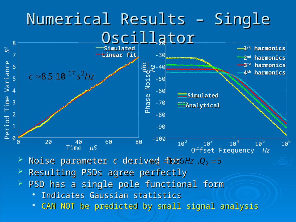
Numerical Results – Single OscillatorNumerical Results – Single Oscillator
Noise parameter Noise parameter cc derived for derived for Resulting PSDs agree perfectlyResulting PSDs agree perfectly PSD has a single pole functional formPSD has a single pole functional form
Indicates Gaussian statisticsIndicates Gaussian statistics CAN NOT be predicted by small signal analysisCAN NOT be predicted by small signal analysis
10 2 103 10 4 10 5 106-100
-90
-80
-70
-60
-50
-40
-30
-2011stst harmonics harmonics
22ndnd harmonics harmonics33rdrd harmonics harmonics44thth harmonics harmonics
Linear fitLinear fit
0 20 40 60 800
1
2
3
4
5
6
7
8SimulatedSimulated
Offset Frequency HzP
hase
Noi
sedB
cH
zTime μS
Per
iod
Tim
e V
aria
nce
s2
AnalyticalAnalytical
SimulatedSimulated