
Influence of the Tool Edge Geometry on Specific Cutting ... R. Rodrigues and Reginaldo T. Coelho 280...
5
Influence of the Tool Edge Geometry on Specific Cutting Energy at High-Speed Cutting J. of the Braz. Soc. of Mech. Sci. & Eng. Copyright 2007 by ABCM July-September 2007, Vol. XXIX, No. 3 / 279 Alessandro R. Rodrigues [email protected] São Paulo State University - UNESP Engineering Faculty of Ilha Solteira Av. Brasil Centro, 56 15385-000 Ilha Solteira, SP. Brazil Reginaldo T. Coelho [email protected] University of São Paulo - USP Engineering School of São Carlos Av. Trabalhador Sãocarlense, 400 13566-590 São Carlos, SP. Brazil Influence of the Tool Edge Geometry on Specific Cutting Energy at High- Speed Cutting This paper presents specific cutting energy measurements as a function of the cutting speed and tool cutting edge geometry. The experimental work was carried out on a vertical CNC machining center with 7,500 rpm spindle rotation and 7.5 kW power. Hardened steels ASTM H13 (50 HRC) were machined at conventional cutting speed and high-speed cutting (HSC). TiN coated carbides with seven different geometries of chip breaker were applied on dry tests. A special milling tool holder with only one cutting edge was developed and the machining forces needed to calculate the specific cutting energy were recorded using a piezoelectric 4-component dynamometer. Workpiece roughness and chip formation process were also evaluated. The results showed that the specific cutting energy decreased 15.5% when cutting speed was increased up to 700%. An increase of 1° in tool chip breaker chamfer angle lead to a reduction in the specific cutting energy about 13.7% and 28.6% when machining at HSC and conventional cutting speed respectively. Furthermore the workpiece roughness values evaluated in all test conditions were very low, closer to those of typical grinding operations (~0.20 μm). Probable adiabatic shear occurred on chip segmentation at HSC. Keywords: specific cutting energy, tool edge geometry, high-speed cutting Introduction 1 Researches in machining processes have occupied a position of central importance in technological field nowadays. The significant economic impact of the machining processes represents approximately 15% of all manufactured products (Merchant, 1998). According to Trent (2000) the machining processes play a relevant role in transforming all metal production in workpieces as well as employ millions of people around the world. Therefore, the growing demand for research in this area represents great challenges for industries which always aim at productivity, quality, flexibility and compatibility to the environment. The machining processes have evolved very fast lately. The improvement on coatings, substrates and tool edge geometries, CNC interfaces and machine tool performance, for instance, have allowed an increase in cutting speeds up to levels denominated High-Speed Cutting - HSC. Despite controversial opinions the main advantages attributed to HSC are high material removal rate, low cutting forces, good workpiece surface finish, high heat transfer, small workpiece distortions and low levels of vibrations during the cutting (Dewes and Aspinwall, 1997; Schulz et al., 2001; Tönshoff et al., 2001). It can be noticed that the machining researches concerning tool geometry and specific cutting energy have been carried out since around 1950. However, most of these studies have been performed by adopting conventional cutting speeds and focusing traditional geometrical parameters of tools, such as rake, clearance, work cutting edge and cutting edge inclination angles. Considering HSC as a current machining concept, it is possible to note that the effect of recent tool geometries i.e. chip breaker and cutting edge shapes on specific cutting energy has not been widely investigated. The specific cutting energy can be considered as an adequate parameter to study HSC. It can represent very well the cutting phenomenon, since it is normalized and is more sensitive to low depth of cut, condition specially applied in HSC operations. King and Hahn (1986) state that specific cutting energy can be understood as a ratio between cutting power and material removal rate, or an equivalent parameter between cutting energy and the volume of removed chip. Paper accepted June, 2007. Technical Editor: Anselmo E. Diniz. Results of cutting force and roughness commonly investigated using HSC have presented divergent tendencies, depending on the consulted source of scientific work. Klocke and Hoppe (2001) turning AISI 1045 steel and 7075 aluminum alloy with cutting speed from 250 to 6,000 m/min verified that the cutting force decreased when 2,000 m/min for steel and 3,000 m/min for aluminum speeds were reached. After these limits the cutting forces increased. Silva (2002) turning Inconel 718 alloy between 300 and 600 m/min observed a constant cutting force with increase in cutting speed. Yousefi and Ichida (2000) investigated the influences of HSC techniques on workpiece roughness, chip formation mechanism and cutting forces when machined aluminum alloys. The researchers concluded that the workpiece roughness increased when cutting speed was increased. They proved that the formation of welded metal on tool minor cutting edge and the chip side flow were the cause in increase of roughness. Despite some controversies HSC is still in great expansion not only at research centers but also in manufacturing industries. In addition, the main factor that limits the HSC evolution depends basically on tool developments, such as coatings, substrates and cutting edge geometries. This paper aims mainly to measure the specific cutting energy under HSC condition and determine possible relationships between tool edge geometries and results of cutting force, surface roughness and chip formation mechanism. Nomenclature A = tool edge chamfer length, mm a p = depth of cut, mm B = tool edge chamfer angle, deg C = chip breaker angle, deg f = feed rate, mm/rev F c = cutting force, N F x = x-axis dynamometer force, N F y = y-axis dynamometer force, N HRC = Rockwell hardness, kgf/mm 2 R a = centerline average roughness, μm r ε = tool corner radius, mm t c = cutting time, s TiN = Titanium nitride u = specific cutting energy, J/mm 3
-
Upload
nguyenkhanh -
Category
Documents
-
view
213 -
download
0
Transcript of Influence of the Tool Edge Geometry on Specific Cutting ... R. Rodrigues and Reginaldo T. Coelho 280...
Influence of the Tool Edge Geometry on Specific Cutting Energy at High-Speed Cutting
J. of the Braz. Soc. of Mech. Sci. & Eng. Copyright 2007 by ABCM July-September 2007, Vol. XXIX, No. 3 / 279
Alessandro R. Rodrigues [email protected]
São Paulo State University - UNESP Engineering Faculty of Ilha Solteira
Av. Brasil Centro, 56 15385-000 Ilha Solteira, SP. Brazil
Reginaldo T. Coelho [email protected]
University of São Paulo - USP Engineering School of São Carlos Av. Trabalhador Sãocarlense, 400 13566-590 São Carlos, SP. Brazil
Influence of the Tool Edge Geometry on Specific Cutting Energy at High-Speed Cutting This paper presents specific cutting energy measurements as a function of the cutting speed and tool cutting edge geometry. The experimental work was carried out on a vertical CNC machining center with 7,500 rpm spindle rotation and 7.5 kW power. Hardened steels ASTM H13 (50 HRC) were machined at conventional cutting speed and high-speed cutting (HSC). TiN coated carbides with seven different geometries of chip breaker were applied on dry tests. A special milling tool holder with only one cutting edge was developed and the machining forces needed to calculate the specific cutting energy were recorded using a piezoelectric 4-component dynamometer. Workpiece roughness and chip formation process were also evaluated. The results showed that the specific cutting energy decreased 15.5% when cutting speed was increased up to 700%. An increase of 1° in tool chip breaker chamfer angle lead to a reduction in the specific cutting energy about 13.7% and 28.6% when machining at HSC and conventional cutting speed respectively. Furthermore the workpiece roughness values evaluated in all test conditions were very low, closer to those of typical grinding operations (~0.20 µm). Probable adiabatic shear occurred on chip segmentation at HSC. Keywords: specific cutting energy, tool edge geometry, high-speed cutting
Introduction
1Researches in machining processes have occupied a position of
central importance in technological field nowadays. The significant
economic impact of the machining processes represents
approximately 15% of all manufactured products (Merchant, 1998).
According to Trent (2000) the machining processes play a relevant
role in transforming all metal production in workpieces as well as
employ millions of people around the world. Therefore, the growing
demand for research in this area represents great challenges for
industries which always aim at productivity, quality, flexibility and
compatibility to the environment.
The machining processes have evolved very fast lately. The
improvement on coatings, substrates and tool edge geometries, CNC
interfaces and machine tool performance, for instance, have allowed
an increase in cutting speeds up to levels denominated High-Speed
Cutting - HSC. Despite controversial opinions the main advantages
attributed to HSC are high material removal rate, low cutting forces,
good workpiece surface finish, high heat transfer, small workpiece
distortions and low levels of vibrations during the cutting (Dewes
and Aspinwall, 1997; Schulz et al., 2001; Tönshoff et al., 2001).
It can be noticed that the machining researches concerning tool
geometry and specific cutting energy have been carried out since
around 1950. However, most of these studies have been performed
by adopting conventional cutting speeds and focusing traditional
geometrical parameters of tools, such as rake, clearance, work
cutting edge and cutting edge inclination angles. Considering HSC
as a current machining concept, it is possible to note that the effect
of recent tool geometries i.e. chip breaker and cutting edge shapes
on specific cutting energy has not been widely investigated.
The specific cutting energy can be considered as an adequate
parameter to study HSC. It can represent very well the cutting
phenomenon, since it is normalized and is more sensitive to low
depth of cut, condition specially applied in HSC operations. King
and Hahn (1986) state that specific cutting energy can be understood
as a ratio between cutting power and material removal rate, or an
equivalent parameter between cutting energy and the volume of
removed chip.
Paper accepted June, 2007. Technical Editor: Anselmo E. Diniz.
Results of cutting force and roughness commonly investigated
using HSC have presented divergent tendencies, depending on the
consulted source of scientific work. Klocke and Hoppe (2001)
turning AISI 1045 steel and 7075 aluminum alloy with cutting speed
from 250 to 6,000 m/min verified that the cutting force decreased
when 2,000 m/min for steel and 3,000 m/min for aluminum speeds
were reached. After these limits the cutting forces increased.
Silva (2002) turning Inconel 718 alloy between 300 and
600 m/min observed a constant cutting force with increase in cutting
speed. Yousefi and Ichida (2000) investigated the influences of HSC
techniques on workpiece roughness, chip formation mechanism and
cutting forces when machined aluminum alloys. The researchers
concluded that the workpiece roughness increased when cutting
speed was increased. They proved that the formation of welded
metal on tool minor cutting edge and the chip side flow were the
cause in increase of roughness.
Despite some controversies HSC is still in great expansion not
only at research centers but also in manufacturing industries. In
addition, the main factor that limits the HSC evolution depends
basically on tool developments, such as coatings, substrates and
cutting edge geometries.
This paper aims mainly to measure the specific cutting energy
under HSC condition and determine possible relationships between
tool edge geometries and results of cutting force, surface roughness
and chip formation mechanism.
Nomenclature
A = tool edge chamfer length, mm
ap = depth of cut, mm
B = tool edge chamfer angle, deg
C = chip breaker angle, deg
f = feed rate, mm/rev
Fc = cutting force, N
Fx = x-axis dynamometer force, N
Fy = y-axis dynamometer force, N
HRC = Rockwell hardness, kgf/mm2
Ra = centerline average roughness, µm
rε = tool corner radius, mm
tc= cutting time, s
TiN = Titanium nitride
u = specific cutting energy, J/mm3
Alessandro R. Rodrigues and Reginaldo T. Coelho
/ Vol. XXIX, No. 3, July-September 2007 ABCM 280
vc = cutting speed, m/min
Vchip = chip volume, mm3
Greek Symbols
αο = tool orthogonal clearance angle, deg γο = tool orthogonal rake angle, deg χr = tool work cutting edge angle, deg
Experimental Apparatus and Procedures
The tests were carried out using a CNC machining center Romi
model Discovery 560. An acquisition system with a piezoelectric
4-component dynamometer Kistler model 9272 was used in order to
record the machining forces during the milling operation. A special
milling tool holder with 85 mm diameter was developed so that only
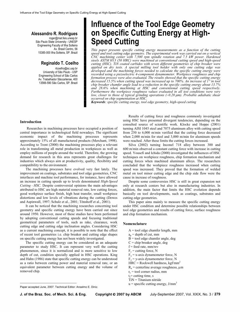
one cutting edge could cut the workpiece material, Fig. 1.
The quenched steel ASTM H13 (50 HRC) with prismatic
geometry 17 x 24 x 32 mm was set on dynamometer through an
appropriate device, Fig. 1. The setup kept the workpiece rigidly
fixed on the dynamometer and assured repeatability in position
when substituting specimens for different machining conditions.
The 32 mm cutting width was maintained constant for all tests.
Figure 1. Experimental setup for measuring specific cutting energy in milling operation.
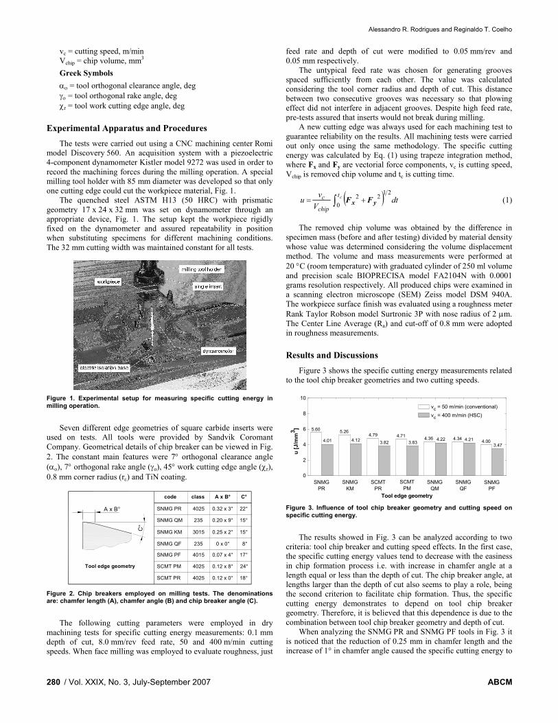
Seven different edge geometries of square carbide inserts were
used on tests. All tools were provided by Sandvik Coromant
Company. Geometrical details of chip breaker can be viewed in Fig.
2. The constant main features were 7° orthogonal clearance angle (αo), 7° orthogonal rake angle (γo), 45° work cutting edge angle (χr), 0.8 mm corner radius (rε) and TiN coating.
Tool edge geometry
C°
SNMG PR 4025 0.32 x 3° 22°
SNMG QM 235 0.20 x 9° 15°
SNMG KM 3015 0.25 x 2° 15°
SNMG QF 235 0 x 0° 8°
SNMG PF 4015 0.07 x 4° 17°
SCMT PM 4025 0.12 x 8° 24°
SCMT PR 4025 0.12 x 0° 18°
code class A x B° C°
A x B°
Figure 2. Chip breakers employed on milling tests. The denominations are: chamfer length (A), chamfer angle (B) and chip breaker angle (C).
The following cutting parameters were employed in dry
machining tests for specific cutting energy measurements: 0.1 mm
depth of cut, 8.0 mm/rev feed rate, 50 and 400 m/min cutting
speeds. When face milling was employed to evaluate roughness, just
feed rate and depth of cut were modified to 0.05 mm/rev and
0.05 mm respectively.
The untypical feed rate was chosen for generating grooves
spaced sufficiently from each other. The value was calculated
considering the tool corner radius and depth of cut. This distance
between two consecutive grooves was necessary so that plowing
effect did not interfere in adjacent grooves. Despite high feed rate,
pre-tests assured that inserts would not break during milling.
A new cutting edge was always used for each machining test to
guarantee reliability on the results. All machining tests were carried
out only once using the same methodology. The specific cutting
energy was calculated by Eq. (1) using trapeze integration method,
where Fx and Fy are vectorial force components, vc is cutting speed,
Vchip is removed chip volume and tc is cutting time.
( ) dtV
vu
ct
chip
c21
0
22∫ += yx FF (1)
The removed chip volume was obtained by the difference in
specimen mass (before and after testing) divided by material density
whose value was determined considering the volume displacement
method. The volume and mass measurements were performed at
20 °C (room temperature) with graduated cylinder of 250 ml volume
and precision scale BIOPRECISA model FA2104N with 0.0001
grams resolution respectively. All produced chips were examined in
a scanning electron microscope (SEM) Zeiss model DSM 940A.
The workpiece surface finish was evaluated using a roughness meter
Rank Taylor Robson model Surtronic 3P with nose radius of 2 µm.
The Center Line Average (Ra) and cut-off of 0.8 mm were adopted
in roughness measurements.
Results and Discussions
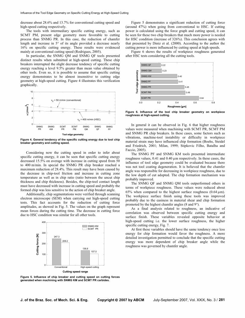
Figure 3 shows the specific cutting energy measurements related
to the tool chip breaker geometries and two cutting speeds.
0
2
4
6
8
10
u [J/mm3]
Tool edge geometry
vc = 50 m/min (conventional)
vc = 400 m/min (HSC)
SNMG
PR
SNMG
KM
SCMT
PR
SCMT
PM
SNMG
QM
SNMG
QF
SNMG
PF
5.60
4.01
5.26
4.124.79
3.82
4.71
3.834.36 4.22 4.34 4.21 4.00
3.47
Figure 3. Influence of tool chip breaker geometry and cutting speed on specific cutting energy.
The results showed in Fig. 3 can be analyzed according to two
criteria: tool chip breaker and cutting speed effects. In the first case,
the specific cutting energy values tend to decrease with the easiness
in chip formation process i.e. with increase in chamfer angle at a
length equal or less than the depth of cut. The chip breaker angle, at
lengths larger than the depth of cut also seems to play a role, being
the second criterion to facilitate chip formation. Thus, the specific
cutting energy demonstrates to depend on tool chip breaker
geometry. Therefore, it is believed that this dependence is due to the
combination between tool chip breaker geometry and depth of cut.
When analyzing the SNMG PR and SNMG PF tools in Fig. 3 it
is noticed that the reduction of 0.25 mm in chamfer length and the
increase of 1° in chamfer angle caused the specific cutting energy to
Influence of the Tool Edge Geometry on Specific Cutting Energy at High-Speed Cutting
J. of the Braz. Soc. of Mech. Sci. & Eng. Copyright 2007 by ABCM July-September 2007, Vol. XXIX, No. 3 / 281
decrease about 28.6% and 13.7% for conventional cutting speed and
high-speed cutting respectively.
The tools with intermediary specific cutting energy, such as
SCMT PM, present edge geometry more favorable to cutting
process than SNMG PR. In this case, the reduction of chamfer
length and increase in 5° of its angle provided a decrease nearly
16% on specific cutting energy. These results were evidenced
mainly at conventional cutting speed (Rodrigues, 2005).
In particular, the SNMG QM and SNMG QF tools presented
distinct results when submitted at high-speed cutting. These chip
breakers interrupted the slight decrease tendency of specific cutting
energy reaching a level 9.5% greater than mean value obtained by
other tools. Even so, it is possible to assume that specific cutting
energy demonstrates to be almost insensitive to cutting edge
geometry at high-speed cutting. Figure 4 illustrates this verification
graphically.
0
2
4
6
8
10
u [J/mm3]
Tool edge geometry
SNMG
PR
SNMG
KM
SCMT
PR
SCMT
PM
SNMG
QM
SNMG
QF
SNMG
PF
vc = 50 m/min (conventional)
vc = 400 m/min (HSC)
Figure 4. General tendency of the specific cutting energy due to tool chip breaker geometry and cutting speed.
Considering now the cutting speed in order to infer about
specific cutting energy, it can be seen that specific cutting energy
decreased 15.5% on average with increase in cutting speed from 50
to 400 m/min. In special the SNMG PR chip breaker reached a
maximum reduction of 28.4%. This result may have been caused by
the decrease in chip-tool friction and increase in cutting zone
temperature as well as in chip ratio (ratio between the uncut chip
thickness and chip thickness). Besides, the chip-tool contact length
must have decreased with increase in cutting speed and probably the
formed chip was less sensitive to the action of chip breaker angle.
Additionally, chip segmentations were verified through scanning
electron microscope (SEM) when carrying out high-speed cutting
tests. This fact accounts for the reduction of cutting force
amplitudes, as showed in Fig. 5. The values on the graph represent
mean forces during the cutting time. The decrease in cutting force
due to HSC condition was similar for all other tools.
Conventional High-speed cutting0
100
200
300
400
Cutting force [N]
Cutting speed range
SNMG KM
SCMT PR
247.3
209.2
136.8
107.0
Figure 5. Influence of chip breaker and cutting speed on cutting forces generated when machining with SNMG KM and SCMT PR carbides.
Figure 5 demonstrates a significant reduction of cutting force
(around 47%) when going from conventional to HSC. If cutting
power is calculated using the force graph and cutting speed, it can
be seen for these two chip breakers that much more power is needed
for HSC condition (increase of 326%). This conclusion agrees with
that presented by Diniz et al. (2000). According to the author the
cutting power is more influenced by cutting speed at high speeds.
Figure 6 shows the results of workpiece roughness generated
after HSC tests considering all the cutting tools.
0.0 0.2 0.4 0.6 0.8
Roughness [µµµµm]
Tool edge geometry
SNMG QF
SNMG QM
SNMG KM
SNMG PF
SNMG PR
SCMT PM
SCMT PR
0.22
0.23
0.40
0.41
0.48
0.49
0.64
Figure 6. Influence of the tool chip breaker geometry on workpiece roughness at high-speed cutting.
In general it can be observed in Fig. 6 that higher roughness
values were measured when machining with SCMT PR, SCMT PM
and SNMG PR chip breakers. In these cases, some factors such as
vibrations, machine-tool instability or difficulty in workpiece
material strain may have influenced chip formation (Boehs, Steidel
and Friedrich, 2001; Milan, 1999; Stipkovic Filho, Batalha and
Faccio, 2005).
The SNMG PF and SNMG KM tools presented intermediate
roughness values, 0.41 and 0.40 µm respectively. In these cases, the
influence of tool edge geometry could be evaluated because there
was not tool coating degeneration. It is believed that the chamfer
angle was responsible for decreasing in workpiece roughness, due to
the low depth of cut adopted. The chip formation mechanism was
probably improved.
The SNMG QF and SNMG QM tools outperformed others in
terms of workpiece roughness. These values were reduced about
65% when compared to the highest surface roughness (0.64 µm).
The workpiece surface finish using these tools was improved
probably due to the easiness in material shear and chip formation
promoted by the highest chamfer angles (8 and 9°).
As a final analysis related to roughness, an indicative of
correlation was observed between specific cutting energy and
surface finish. These variables revealed opposite behavior at
high-speed cutting i.e. the lower surface roughness, the higher
specific cutting energy, Fig. 7.
At first these variables should have the same tendency once less
energy for chip formation would favor the roughness. A more
detailed investigation permitted to conclude that the specific cutting
energy was more dependent of chip breaker angle while the
roughness was governed by chamfer angle.
Alessandro R. Rodrigues and Reginaldo T. Coelho
/ Vol. XXIX, No. 3, July-September 2007 ABCM 282
0.0
0.2
0.4
0.6
0.8
1.0
SCMT
PR
SCMT
PM
SNMG
PR
SNMG
PF
SNMG
KM
SNMG
QM
SNMG
QF
Tool edge geometry
Ra [µµ µµm]
0
1
2
3
4
5
u [J/mm3]
Roughness
Specific cutting energy
Figure 7. Behavior of specific cutting energy and workpiece roughness.
Considering a further comparison it is fully possible to associate
the measured roughness values to those of grinding process.
According to Ferraresi (1977), the workpiece roughness
measurements (Ra) for milling processes lie in 0.8 - 6.3 µm range.
These values are diminished to 0.2 - 3.2 µm for grinding processes.
The great advantage in using defined tool geometry bases on
controlling its edge geometry. Thus, typical workpiece roughness
from grinding processes could be reached by this research work.
Figure 8 concludes this result discussion by showing two
samples of chips removed during the tests performed under
conventional cutting speed and high-speed cutting.
Figure 8. Hardened chip samples obtained at (a) conventional cutting speed and (b) HSC.
The images presented above represent the central focus of this
chip visual characterization. They illustrate that the chip formation
process composed by both elastic and plastic strain was probably
modified due to cutting speed variation. It is relevant to mention that
visual analyses of tool rake face were done for each tested insert and
built-up edge occurrences were not verified. In spite of employing
on trials low cutting speed (50 m/min) the built-up edge was not
formed likely due to low ductility of machined material. The
built-up edge could have influenced on formation of chips and
modified both their morphology and microstructure (Shaw, 2004).
Figure 8a shows a chip portion where the continuity of lamellas
is clearly visible, although there is a saw-tooth shape very reduced.
However, Fig. 8b illustrates more evidently an accentuated chip
segmentation level, including regions of nucleation, growth and
arrest of cracks on the chip top surface. They may have been
generated by slight chip curvature when machined at high strain rate
associated to the low workpiece material plasticity. These chip
samples were obtained with all cutting parameters maintained
constant including the tool edge geometry. At first the segmented chip presented in Fig. 8b may have been
produced due to adiabatic shear process since its morphology and dynamics of formation were governed by high-speed cutting applied in machining of hardened material. Meantime, this classification can be only confirmed by metallographic examinations of chip which must present intense deformation between the lamellas.
Segmented chips generated by adiabatic shear present intense concentrated shear bands and they are formed above a certain speed, such as high-speed cutting. High resistance alloys and hardened materials with low thermal properties cause either catastrophic or thermoplastic shear, where the ductility effect generated by increase
in temperature overcomes the hardening effect of material originated due to high strain rates.
Finally, other relevant aspect to approach refers to the definition
which literature uses to define the range between conventional
cutting speed and high-speed cutting. In general, this distinction
bases on specification of certain cutting speed values, because it is a
criterion more feasible technologically. However, the cutting speed
of 400 m/min assumed as high-speed cutting in this work was an
apparently correct chosen since it caused modifications in chip
formation mechanism.
Conclusions
The following final conclusions are summarized bellow:
The tool chip breaker geometry causes influence on specific
cutting energy behavior. Even small modifications on cutting edge
geometry affect the cutting force levels and specific cutting energy
values;
It is more evident the effect of cutting edge geometry on specific
cutting energy at conventional cutting speed than at high-speed
cutting. The reduction of 0.25 mm in chamfer length and increase of
1° in chamfer angle (from SNMG PR to SNMG PF tools) caused a
reduction on specific cutting energy nearly 28.6% and 13.7% for
conventional cutting speed and high-speed cutting respectively;
The tests carried out at high-speed cutting provided cutting
forces significantly lower than those obtained at conventional
cutting speed condition. The SNMG KM and SCMT PR tools
reduced the force levels about 47%;
There was an indication of correlation between workpiece
surface finish and specific cutting energy for HSC condition. In
general, the higher the specific cutting energy, the lower the
workpiece roughness. The tool edge chamfer angle and chip breaker
angle caused distinct influences on this behavior probably;
The highest workpiece roughness measured was 0.64 µm using
SCMT PR chip breaker and the lowest value was 0.22 µm for
SNMG QF tool;
The chip formation mechanism could be classified into
continuous chip for lowest cutting speed and segmented chip for
highest cutting speed.
Acknowledgments
The authors are grateful to the State of São Paulo Research
Foundation (FAPESP) by financial support and to the Laboratory
for Optimization of Manufacturing Processes (OPF) at the
Engineering School of São Carlos (EESC-USP).
References
Boehs, L., Steidel, P.S. and Friedrich, D., 2001, “Influência dos Parâmetros de Usinagem e da Geometria da Ferramenta sobre a Rugosidade Cinemática e de Processo” (In Portuguese), Proceedings of the 16th Brazilian Congress of Mechanical Engineering, Vol.1, Uberlândia, MG, Brazil, pp. 467-476.
Dewes, R.C. & Aspinwall, D.K., 1997, “A Review of Ultra High Speed Milling of Hardened Steels”, Journal of Materials Processing Technology, No. 69, pp. 1-17.
Diniz, A.E., Marcondes, F.C. and Coppini, N.L., 2000, “Tecnologia da Usinagem dos Materiais”, Ed. Artliber, São Paulo, Brazil, 244 p.
Ferraresi, D., 1977, “Fundamentos da Usinagem dos Metais”, Ed. Edgard Blücher, São Paulo, Brazil, 751 p.
King, R.I. & Hahn, R.S., 1986, “Handbook of Modern Grinding Technology”, Ed. Chapman and Hall, USA, 360 p.
Klocke, F. & Hoppe, S., 2001, “Mechanisms of Chip Formation in High Speed Cutting”, In: Schulz, H. (Editor), “Scientific Fundamentals of HSC”, Ed. Druckhaus, Munich, Germany, pp.1-10.

Influence of the Tool Edge Geometry on Specific Cutting Energy at High-Speed Cutting
J. of the Braz. Soc. of Mech. Sci. & Eng. Copyright 2007 by ABCM July-September 2007, Vol. XXIX, No. 3 / 283
Merchant, M.E., 1998, “An Interpretive Look at the 20th Century Research on Modeling of Machining”, Machining Science and Technology, Vol. 2, pp. 157-163.
Milan, J.C.G., 1999, “Usinabilidade de Aços para Moldes para Plásticos” (In Portuguese), M.Sc. Dissertation, Federal University of Uberlândia (UFU), Uberlândia, MG, Brazil, 99 p.
Rodrigues, A.R., 2005, “Estudo da Geometria de Arestas de Corte Aplicadas em Usinagem com Alta Velocidade de Corte” (In Portuguese), Ph.D. Thesis, Engineering School of São Carlos, University of São Paulo, São Carlos, SP, Brazil, 227 p.
Schulz, H. et al., 2001, “High-Speed Machining - Fundamentals and Industrial Application”, Proceedings of 6th International Seminary of the High Technology - Advanced Manufacture, Piracicaba, SP, Brazil, pp. 25-44.
Shaw, M.C., 2004, “Metal Cutting Principles”, Ed. Oxford University, England, 651 p.
Silva, L.R., 2002, “Estudo da Geometria da Aresta de Corte de Ferramentas Aplicadas ao Torneamento de Superligas à Base de Níquel com Alta Velocidade de Corte” (In Portuguese), Ph.D. Thesis, Engineering School of São Carlos, University of São Paulo, São Carlos, SP, Brazil, 211 p.
Stipkovic Filho, M., Batalha, G.F. and Faccio, I., 2005, “Acabamento Superficial a Altíssima Velocidade de Corte” (In Portuguese), Máquinas e Metais, No. 468, pp. 142-153.
Tönshoff, H.K. et al., 2001, “High-Speed or High-Performance Cutting - A Comparison of New Machining Technologies”, Production Engineering, Vol. 8, No. 1, pp. 5-8.
Trent, E.M. & Wright, P.K., 2000, “Metal Cutting”, Ed. Butterworth Heinemann, Boston, USA, 446 p.
Yousefi, R. & Ichida, Y., 2000, “A Study on Ultra-High-Speed Cutting of Aluminum Alloy: Formation of Welded Metal on the Secondary Cutting Edge of the Tool and Its Effects on the Quality of Finished Surface”, Precision Engineering, Vol. 24, pp. 371-376.


![Análise de Algoritmos Slides de Paulo Feofiloffcris/aulas/11_1_338/slides/aula23.pdf · Slides de Paulo Feofiloff [com erros do coelho e agora também da cris] Algoritmos – p.](https://static.fdocument.org/doc/165x107/5fcb707cfc881b231a7395fc/anlise-de-algoritmos-slides-de-paulo-crisaulas111338slidesaula23pdf-slides.jpg)