Influence of P-Delta Effect on Ductility and Vulnerability ... shear force occurs. The line joining...
12
Send Orders for Reprints to [email protected] The Open Civil Engineering Journal, 2015, 9, (Suppl. 1, M 13) 351-362 351 1874-1495/15 2015 Bentham Open Open Access Influence of P-Delta Effect on Ductility and Vulnerability of SMRF Steel Buildings Juan Carlos Vielma Pérez 1,2,* and Manuel Antonio Cando Loachamín 2 1 Departamento de Ingeniería Estructural, Universidad Centroccidental Lisandro Alvarado, Barquisimeto, Venezuela 2 Departamento de Ciencias de la Tierra y la Construcción, Universidad de las Fuerzas Armadas, Sangolquí, Ecuador Abstract: Current earthquake-resistant procedures prescribe generic values for the response reductions factors, regardless of the configurational characteristics of the designed buildings. It is well know that these response reduction factors values reflect the expected behavior of the structures when they are under strong ground motions, being this seismic behavior usually evaluated through ductility and over-strength. In this work calculated values of the ductility of special moment-resisting steel frames with different span lengths and designed according the Ecuadorian Construction Code are presented. Results show that the buildings’ ductility is strongly influenced by the spans length and they would reach inadequate values if the second-order effect P-∆ occur, and then indicating that the structures are more vulnerable than struc- tures not affected by P-∆ effect. Keywords: Ductility, non-linear analysis, P-Δ effect, span length, vulnerability. 1. INTRODUCTION The procedures used for the seismic assessment of struc- tures are usually based on the comparison of the coefficients which characterize the response and led to determine whether the behavior is adequate or not [1, 2]. Among the main coefficients used the ductility is the most important. It is computed from the pseudo-static non-linear analysis (Pushover analysis) from this Equation [3]: μ = ! u ! y (1) In this Equation Δ u and Δ y are the ultimate displacement and the yield displacement, respectively. A lot of procedures focused in the structural ductility have been presented re- cently [4, 5]. In the Methodology of FEMA P695 [6] this coefficient has received special attention, introducing a new approach in which the ductility μ T is formulated based in the structural period, according to: μ T = ! u " y ,eff (2) where Δ u is the above mentioned ultimate displacement which corresponds to the displacement of the point where the base shear force drops 10% of the maximum value of the Pushover curve and ! y ,eff is the effective yield displacement. There are different criteria used for defining the dis- placements used to determine the ductility. For this reason it *Address correspondence to this author at the Departamento de Ciencias de la Tierra y la Construcción, Universidad de las Fuerzas Armadas, Sangolquí, Ecuador; Tel: +582512592135; Fax: +582512592104; E-mail: [email protected] is important to apply a method who leads to compute the ductility in an objective way, besides because ductility is an important component for calculating the system response reduction factor, according to the ATC 19 [7]. For the specific case of moment-resisting steel framed structures, in which the excessive displacements produced by the structural flexibility under lateral forces may introduce second-order effects like the P-Δ effect, it is important to pay special attention to the determination of the displacements required for the ductility computation. For structures with intermediate and long spans, the action of gravitational forces tend to anticipate the effect of the P-Δ effect, because they produce greater moments even for the same displace- ments of similar structures whit short spans. In this work the results of a study about ductility of mo- ment resisting framed steel buildings designed according the Ecuadorian Construction Code (NEC) [8] are presented. In the study was necessary to apply some changes in the as- sessment process, especially in the determination of the yield and ultimate displacements for ductility determination. Duc- tility is an important coefficient for the seismic characteriza- tion and in order to determine the vulnerability of structures. In the next section special a comprehensive study of the P-Δ effect is presented. 2. THE P-Δ EFFECT In non-linear pseudo-static analysis, there are two loads types which are applied separately. The first group of loads corresponds to gravitational loads (death loads combined with live loads). The second one corresponds to the equiva- lent lateral forces that simulate the effect of the earthquakes when they hit the structures.
Transcript of Influence of P-Delta Effect on Ductility and Vulnerability ... shear force occurs. The line joining...
Send Orders for Reprints to [email protected]
The Open Civil Engineering Journal, 2015, 9, (Suppl. 1, M 13) 351-362 351
1874-1495/15 2015 Bentham Open
Open Access
Influence of P-Delta Effect on Ductility and Vulnerability of SMRF Steel Buildings
Juan Carlos Vielma Pérez1,2,* and Manuel Antonio Cando Loachamín2
1Departamento de Ingeniería Estructural, Universidad Centroccidental Lisandro Alvarado, Barquisimeto, Venezuela 2Departamento de Ciencias de la Tierra y la Construcción, Universidad de las Fuerzas Armadas, Sangolquí, Ecuador
Abstract: Current earthquake-resistant procedures prescribe generic values for the response reductions factors, regardless of the configurational characteristics of the designed buildings. It is well know that these response reduction factors values reflect the expected behavior of the structures when they are under strong ground motions, being this seismic behavior usually evaluated through ductility and over-strength. In this work calculated values of the ductility of special moment-resisting steel frames with different span lengths and designed according the Ecuadorian Construction Code are presented. Results show that the buildings’ ductility is strongly influenced by the spans length and they would reach inadequate values if the second-order effect P-∆ occur, and then indicating that the structures are more vulnerable than struc-tures not affected by P-∆ effect.
Keywords: Ductility, non-linear analysis, P-Δ effect, span length, vulnerability.
1. INTRODUCTION
The procedures used for the seismic assessment of struc-tures are usually based on the comparison of the coefficients which characterize the response and led to determine whether the behavior is adequate or not [1, 2]. Among the main coefficients used the ductility is the most important. It is computed from the pseudo-static non-linear analysis (Pushover analysis) from this Equation [3]:
µ =!
u
!y
(1)
In this Equation Δu and Δy are the ultimate displacement and the yield displacement, respectively. A lot of procedures focused in the structural ductility have been presented re-cently [4, 5]. In the Methodology of FEMA P695 [6] this coefficient has received special attention, introducing a new approach in which the ductility µT is formulated based in the structural period, according to:
µT=
!u
"y ,eff
(2)
where Δu is the above mentioned ultimate displacement which corresponds to the displacement of the point where the base shear force drops 10% of the maximum value of the Pushover curve and
!
y ,eff is the effective yield displacement.
There are different criteria used for defining the dis-placements used to determine the ductility. For this reason it
*Address correspondence to this author at the Departamento de Ciencias de la Tierra y la Construcción, Universidad de las Fuerzas Armadas, Sangolquí, Ecuador; Tel: +582512592135; Fax: +582512592104; E-mail: [email protected]
is important to apply a method who leads to compute the ductility in an objective way, besides because ductility is an important component for calculating the system response reduction factor, according to the ATC 19 [7].
For the specific case of moment-resisting steel framed structures, in which the excessive displacements produced by the structural flexibility under lateral forces may introduce second-order effects like the P-Δ effect, it is important to pay special attention to the determination of the displacements required for the ductility computation. For structures with intermediate and long spans, the action of gravitational forces tend to anticipate the effect of the P-Δ effect, because they produce greater moments even for the same displace-ments of similar structures whit short spans.
In this work the results of a study about ductility of mo-ment resisting framed steel buildings designed according the Ecuadorian Construction Code (NEC) [8] are presented. In the study was necessary to apply some changes in the as-sessment process, especially in the determination of the yield and ultimate displacements for ductility determination. Duc-tility is an important coefficient for the seismic characteriza-tion and in order to determine the vulnerability of structures.
In the next section special a comprehensive study of the P-Δ effect is presented.
2. THE P-Δ EFFECT
In non-linear pseudo-static analysis, there are two loads types which are applied separately. The first group of loads corresponds to gravitational loads (death loads combined with live loads). The second one corresponds to the equiva-lent lateral forces that simulate the effect of the earthquakes when they hit the structures.
352 The Open Civil Engineering Journal, 2015, Volume 9 Pérez and Loachamín
The main methods for structural analysis include the fol-lowing characteristics: • Linear elastic first-order analysis • Linear elastic second-order analysis • Non-linear first-order analysis • Non-linear second-order analysis
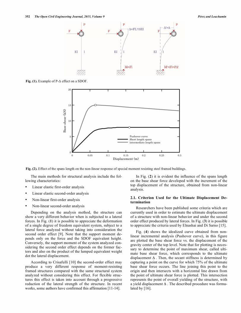
Depending on the analysis method, the structure can show a very different behavior when is subjected to a lateral forces. In Fig. (1) it is possible to appreciate the deformation of a single degree of freedom equivalent system, subject to a lateral force analyzed without taking into consideration the second order effect [9]. Note that the support moment de-pends only on the force and the SDOF equivalent height. Conversely, the support moment of the system analyzed con-sidering the second order effect depends on the former fac-tors and also on the product of the lumped equivalent weight dot the lateral displacement.
According to Crisafulli [10] the second-order effect may produce a very different response of moment-resisting framed structures compared with the same structural system analyzed without considering this effect. For flexible struc-tures this effect is taken into account through a progressive reduction of the lateral strength of the structure. In recent works, some authors have confirmed this affirmation [11-14].
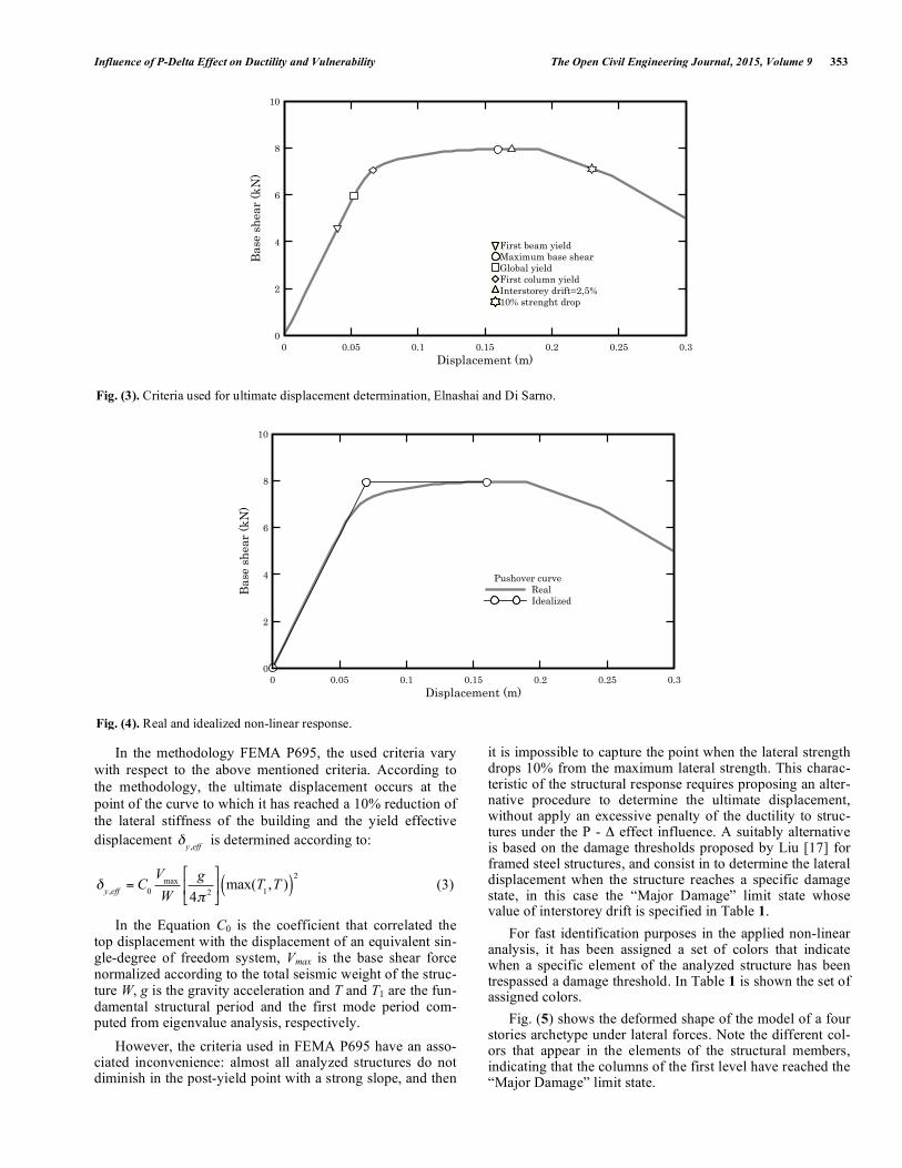
In Fig. (2) it is evident the influence of the spans length on the base shear force developed with the increment of the top displacement of the structure, obtained from non-linear analysis.
2.1. Criterion Used for the Ultimate Displacement De-termination
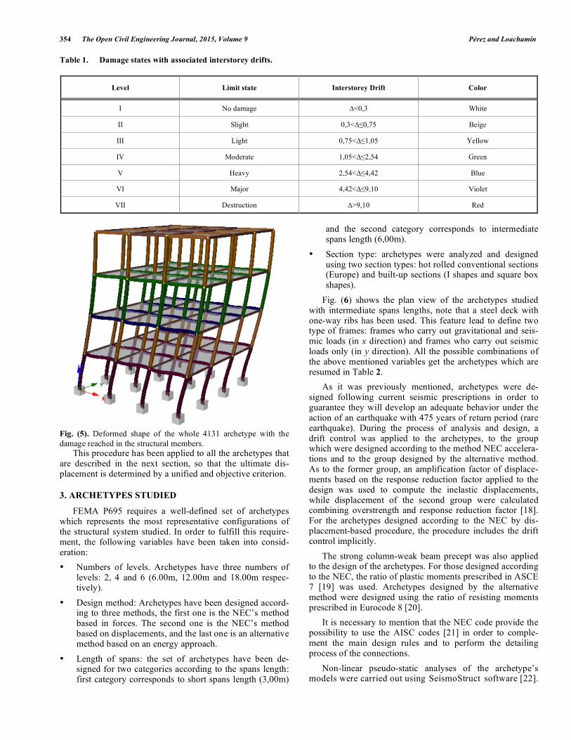
Researchers have been published some criteria which are currently used in order to estimate the ultimate displacement of a structure with non-linear behavior and under the second order effect produced by lateral forces. In Fig. (3) it is possible to appreciate the criteria used by Elnashai and Di Sarno [15].
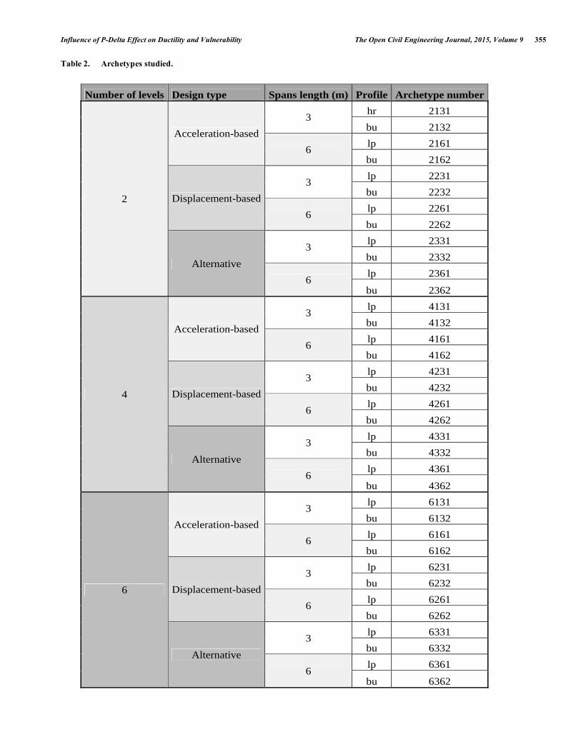
Fig. (4) shows the idealized curve obtained from non-linear incremental analysis (Pushover curve), in this figure are plotted the base shear force vs. the displacement of the gravity center of the top level. Note that for plotting is neces-sary to determine the point of maximum shear, called ulti-mate base shear force, which corresponds to the ultimate displacement Δ . Then, the secant stiffness is determined by capturing a point on the curve for which 75% of the ultimate base shear force occurs. The line joining this point to the origin and then intersects with a horizontal line drawn from the point of ultimate shear force is plotted. This intersection represents the point of overall yielding of the structure, with a yield displacement Δ . The described procedure was formu-lated by [16].
Fig. (1). Example of P-Δ effect on a SDOF.
Fig. (2). Effect of the spans length on the non-linear response of special moment resisting steel framed buildings.
Displacement (m)
Bas
e sh
ear
(kN
)
0 0.05 0.1 0.15 0.2 0.25 0.30
5
10
15
20
Pushover curveShort length spansintermediate length spans
Influence of P-Delta Effect on Ductility and Vulnerability The Open Civil Engineering Journal, 2015, Volume 9 353
In the methodology FEMA P695, the used criteria vary with respect to the above mentioned criteria. According to the methodology, the ultimate displacement occurs at the point of the curve to which it has reached a 10% reduction of the lateral stiffness of the building and the yield effective displacement
!
y ,eff is determined according to:
!y ,eff
= C0
Vmax
W
g
4" 2
#
$%
&
'( max(T
1,T )( )
2
(3)
In the Equation C0 is the coefficient that correlated the top displacement with the displacement of an equivalent sin-gle-degree of freedom system, Vmax is the base shear force normalized according to the total seismic weight of the struc-ture W, g is the gravity acceleration and T and T1 are the fun-damental structural period and the first mode period com-puted from eigenvalue analysis, respectively.
However, the criteria used in FEMA P695 have an asso-ciated inconvenience: almost all analyzed structures do not diminish in the post-yield point with a strong slope, and then
it is impossible to capture the point when the lateral strength drops 10% from the maximum lateral strength. This charac-teristic of the structural response requires proposing an alter-native procedure to determine the ultimate displacement, without apply an excessive penalty of the ductility to struc-tures under the P - Δ effect influence. A suitably alternative is based on the damage thresholds proposed by Liu [17] for framed steel structures, and consist in to determine the lateral displacement when the structure reaches a specific damage state, in this case the “Major Damage” limit state whose value of interstorey drift is specified in Table 1.
For fast identification purposes in the applied non-linear analysis, it has been assigned a set of colors that indicate when a specific element of the analyzed structure has been trespassed a damage threshold. In Table 1 is shown the set of assigned colors.
Fig. (5) shows the deformed shape of the model of a four stories archetype under lateral forces. Note the different col-ors that appear in the elements of the structural members, indicating that the columns of the first level have reached the “Major Damage” limit state.
Fig. (3). Criteria used for ultimate displacement determination, Elnashai and Di Sarno.
Fig. (4). Real and idealized non-linear response.
Displacement (m)
Bas
e sh
ear
(kN
)
0 0.05 0.1 0.15 0.2 0.25 0.30
2
4
6
8
10
First beam yieldMaximum base shearGlobal yieldFirst column yieldInterstorey drift=2,5%10% strenght drop
Displacement (m)
Bas
e sh
ear
(kN
)
0 0.05 0.1 0.15 0.2 0.25 0.30
2
4
6
8
10
Pushover curveRealIdealized
354 The Open Civil Engineering Journal, 2015, Volume 9 Pérez and Loachamín
Table 1. Damage states with associated interstorey drifts.
Level Limit state Interstorey Drift Color
I No damage ∆<0,3 White
II Slight 0,3<∆≤0,75 Beige
III Light 0,75<∆≤1,05 Yellow
IV Moderate 1,05<∆≤2,54 Green
V Heavy 2,54<∆≤4,42 Blue
VI Major 4,42<∆≤9,10 Violet
VII Destruction ∆>9,10 Red
Fig. (5). Deformed shape of the whole 4131 archetype with the damage reached in the structural members.
This procedure has been applied to all the archetypes that are described in the next section, so that the ultimate dis-placement is determined by a unified and objective criterion.
3. ARCHETYPES STUDIED
FEMA P695 requires a well-defined set of archetypes which represents the most representative configurations of the structural system studied. In order to fulfill this require-ment, the following variables have been taken into consid-eration: • Numbers of levels. Archetypes have three numbers of
levels: 2, 4 and 6 (6.00m, 12.00m and 18.00m respec-tively).
• Design method: Archetypes have been designed accord-ing to three methods, the first one is the NEC’s method based in forces. The second one is the NEC’s method based on displacements, and the last one is an alternative method based on an energy approach.
• Length of spans: the set of archetypes have been de-signed for two categories according to the spans length: first category corresponds to short spans length (3,00m)
and the second category corresponds to intermediate spans length (6,00m).
• Section type: archetypes were analyzed and designed using two section types: hot rolled conventional sections (Europe) and built-up sections (I shapes and square box shapes).
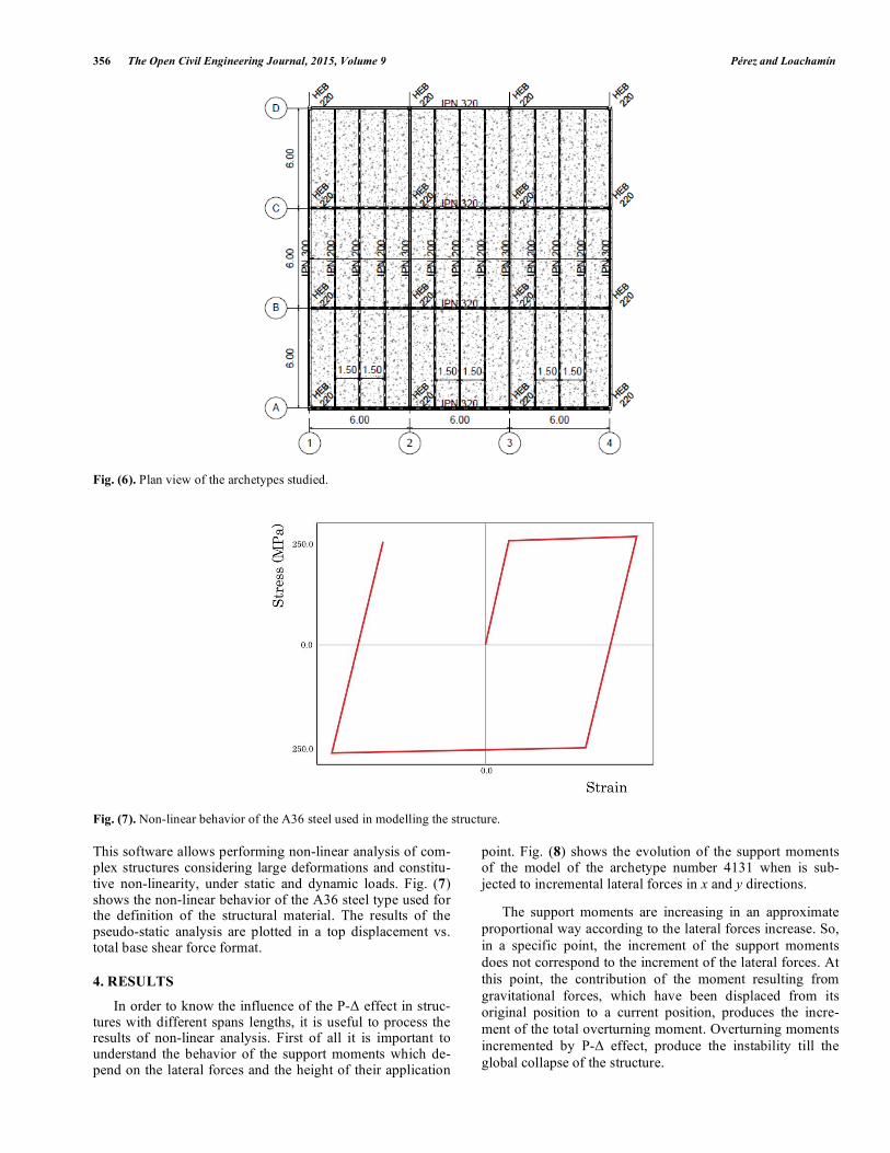
Fig. (6) shows the plan view of the archetypes studied with intermediate spans lengths, note that a steel deck with one-way ribs has been used. This feature lead to define two type of frames: frames who carry out gravitational and seis-mic loads (in x direction) and frames who carry out seismic loads only (in y direction). All the possible combinations of the above mentioned variables get the archetypes which are resumed in Table 2.
As it was previously mentioned, archetypes were de-signed following current seismic prescriptions in order to guarantee they will develop an adequate behavior under the action of an earthquake with 475 years of return period (rare earthquake). During the process of analysis and design, a drift control was applied to the archetypes, to the group which were designed according to the method NEC accelera-tions and to the group designed by the alternative method. As to the former group, an amplification factor of displace-ments based on the response reduction factor applied to the design was used to compute the inelastic displacements, while displacement of the second group were calculated combining overstrength and response reduction factor [18]. For the archetypes designed according to the NEC by dis-placement-based procedure, the procedure includes the drift control implicitly.
The strong column-weak beam precept was also applied to the design of the archetypes. For those designed according to the NEC, the ratio of plastic moments prescribed in ASCE 7 [19] was used. Archetypes designed by the alternative method were designed using the ratio of resisting moments prescribed in Eurocode 8 [20].
It is necessary to mention that the NEC code provide the possibility to use the AISC codes [21] in order to comple-ment the main design rules and to perform the detailing process of the connections.
Non-linear pseudo-static analyses of the archetype’s models were carried out using SeismoStruct software [22].
Influence of P-Delta Effect on Ductility and Vulnerability The Open Civil Engineering Journal, 2015, Volume 9 355
Table 2. Archetypes studied.
Number of levels Design type Spans length (m) Profile Archetype number
2
Acceleration-based
3 hr 2131
bu 2132
6 lp 2161
bu 2162
Displacement-based
3 lp 2231
bu 2232
6 lp 2261
bu 2262
Alternative
3 lp 2331
bu 2332
6 lp 2361
bu 2362
4
Acceleration-based
3 lp 4131
bu 4132
6 lp 4161
bu 4162
Displacement-based
3 lp 4231
bu 4232
6 lp 4261
bu 4262
Alternative
3 lp 4331
bu 4332
6 lp 4361
bu 4362
6
Acceleration-based
3 lp 6131
bu 6132
6 lp 6161
bu 6162
Displacement-based
3 lp 6231
bu 6232
6 lp 6261
bu 6262
Alternative
3 lp 6331
bu 6332
6 lp 6361
bu 6362
356 The Open Civil Engineering Journal, 2015, Volume 9 Pérez and Loachamín
Fig. (6). Plan view of the archetypes studied.
Fig. (7). Non-linear behavior of the A36 steel used in modelling the structure.
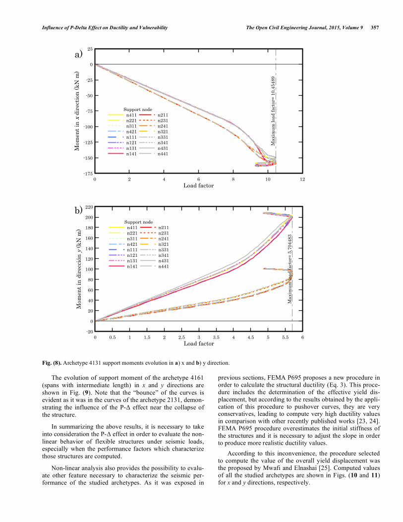
This software allows performing non-linear analysis of com-plex structures considering large deformations and constitu-tive non-linearity, under static and dynamic loads. Fig. (7) shows the non-linear behavior of the A36 steel type used for the definition of the structural material. The results of the pseudo-static analysis are plotted in a top displacement vs. total base shear force format.
4. RESULTS
In order to know the influence of the P-Δ effect in struc-tures with different spans lengths, it is useful to process the results of non-linear analysis. First of all it is important to understand the behavior of the support moments which de-pend on the lateral forces and the height of their application
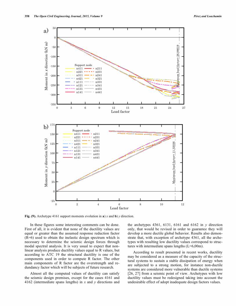
point. Fig. (8) shows the evolution of the support moments of the model of the archetype number 4131 when is sub-jected to incremental lateral forces in x and y directions.
The support moments are increasing in an approximate proportional way according to the lateral forces increase. So, in a specific point, the increment of the support moments does not correspond to the increment of the lateral forces. At this point, the contribution of the moment resulting from gravitational forces, which have been displaced from its original position to a current position, produces the incre-ment of the total overturning moment. Overturning moments incremented by P-Δ effect, produce the instability till the global collapse of the structure.
Influence of P-Delta Effect on Ductility and Vulnerability The Open Civil Engineering Journal, 2015, Volume 9 357
Fig. (8). Archetype 4131 support moments evolution in a) x and b) y direction.
The evolution of support moment of the archetype 4161 (spans with intermediate length) in x and y directions are shown in Fig. (9). Note that the “bounce” of the curves is evident as it was in the curves of the archetype 2131, demon-strating the influence of the P-Δ effect near the collapse of the structure.
In summarizing the above results, it is necessary to take into consideration the P-Δ effect in order to evaluate the non-linear behavior of flexible structures under seismic loads, especially when the performance factors which characterize those structures are computed.
Non-linear analysis also provides the possibility to evalu-ate other feature necessary to characterize the seismic per-formance of the studied archetypes. As it was exposed in
previous sections, FEMA P695 proposes a new procedure in order to calculate the structural ductility (Eq. 3). This proce-dure includes the determination of the effective yield dis-placement, but according to the results obtained by the appli-cation of this procedure to pushover curves, they are very conservatives, leading to compute very high ductility values in comparison with other recently published works [23, 24]. FEMA P695 procedure overestimates the initial stiffness of the structures and it is necessary to adjust the slope in order to produce more realistic ductility values.
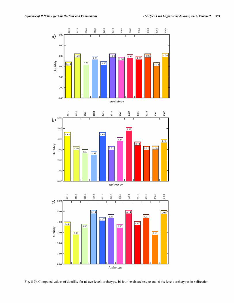
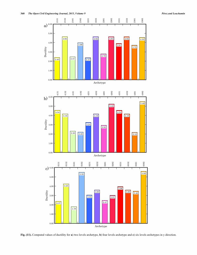
According to this inconvenience, the procedure selected to compute the value of the overall yield displacement was the proposed by Mwafi and Elnashai [25]. Computed values of all the studied archetypes are shown in Figs. (10 and 11) for x and y directions, respectively.
Load factor
Mom
ent
in x
dir
ecti
on (
kN m
)
0 2 4 6 8 10 12-175
-150
-125
-100
-75
-50
-25
0
25
Max
imu
m lo
ad f
acto
r= 1
0,45
489
a)
Support noden411n221n311n421n111n121n131n141
n211n231n241n321n331n341n431n441
Load factor
Mom
ent
in d
irec
ción
y (
kN m
)
0 0.5 1 1.5 2 2.5 3 3.5 4 4.5 5 5.5 6-20
0
20
40
60
80
100
120
140
160
180
200
220
Max
imu
m l
oad
fact
or=
5,70
4483
b)Support node
n411n221n311n421n111n121n131n141
n211n231n241n321n331n341n431n441
358 The Open Civil Engineering Journal, 2015, Volume 9 Pérez and Loachamín
Fig. (9). Archetype 4161 support moments evolution in a) x and b) y direction.
In these figures some interesting comments can be done. First of all, it is evident that none of the ductility values are equal or greater than the assumed response reduction factor (R=6) used to obtain the inelastic design spectrum which is necessary to determine the seismic design forces through modal spectral analysis. It is very usual to expect that non-linear analysis produce ductility values equal to R values, but according to ATC 19 the structural ductility is one of the components used in order to compute R factor. The other main components of R factor are the overstrength and re-dundancy factor which will be subjects of future research.
Almost all the computed values of ductility can satisfy the seismic design premises, except for the cases 4161 and 4162 (intermediate spans lengths) in x and y directions and
the archetypes 4361, 6131, 6161 and 6162 in y direction only, that would be revised in order to guarantee they will develop a more ductile global behavior. Results also demon-strate that, with exception of archetype 4361, all the arche-types with resulting low ductility values correspond to struc-tures with intermediate spans lengths (L=6,00m).
According to result presented in recent works, ductility may be considered as a measure of the capacity of the struc-tural systems to sustain a stable dissipation of energy when are subjected to a strong motion, for instance non-ductile systems are considered more vulnerable than ductile systems [26, 27] from a seismic point of view. Archetypes with low ductility values must be redesigned taking into account the undesirable effect of adopt inadequate design factors values.
Load factor
Mom
ent
in x
dir
ecti
on (
kN m
)
0 3 6 9 12 15 18 21 24 27-350
-300
-250
-200
-150
-100
-50
0
50
Max
imu
m lo
ad f
acto
r= 2
6,06
619
a)
Support noden411n221n311n421n111n121n131n141
n211n231n241n321n331n341n431n441
Load factor
Mom
ent
in y
dir
ecti
on (
kN m
)
0 2 4 6 8 10 12-25
0
25
50
75
100
125
150
175
Max
imu
m l
oad
fact
or=
11,3
2036
b)Support node
n411n221n311n421n111n121n131n141
n211n231n241n321n331n341n431n441
Influence of P-Delta Effect on Ductility and Vulnerability The Open Civil Engineering Journal, 2015, Volume 9 359
Fig. (10). Computed values of ductility for a) two levels archetype, b) four levels archetype and c) six levels archetypes in x direction.
Archetype
Ductility
0.00
1.00
2.00
3.00
4.00
5.00
6.00
2131
2132
2161
2162
2231
2232
2261
2262
2331
2332
2361
2362
3.44
4.20
3.51
4.00
3.50
4.203.90
4.154.00
4.20
3.38
4.25
a)
Archetype
Ductility
0.00
1.00
2.00
3.00
4.00
5.00
6.00
4131
4132
4161
4162
4231
4232
4261
4262
4331
4332
4361
4362
4.63
3.303.00
2.83
4.63
3.32
4.14
5.12
3.74
3.32 3.35
4.00
b)
Archetype
Ductility
0.00
1.00
2.00
3.00
4.00
5.00
6.00
6131
6132
6161
6162
6231
6232
6261
6262
6331
6332
6361
6362
4.02
3.16
3.80
5.14
4.474.71
3.80
5.14
4.07
4.71
3.13
5.08
c)
360 The Open Civil Engineering Journal, 2015, Volume 9 Pérez and Loachamín
Fig. (11). Computed values of ductility for a) two levels archetype, b) four levels archetype and c) six levels archetypes in y direction.
Archetype
Ductility
0.00
1.00
2.00
3.00
4.00
5.00
6.00
2131
2132
2161
2162
2231
2232
2261
2262
2331
2332
2361
2362
2.40
4.62
2.47
3.99
2.37
4.62
2.78
4.63
3.91
4.62
3.72
4.55
a)
Archetype
Ductility
0.00
1.00
2.00
3.00
4.00
5.00
6.00
4131
4132
4161
4162
4231
4232
4261
4262
4331
4332
4361
4362
4.54
4.16
2.30 2.20
3.24
4.16
2.93
5.22
4.54
4.16
2.18
5.49
b)
Archetype
Ductility
0.00
1.00
2.00
3.00
4.00
5.00
6.00
6131
6132
6161
6162
6231
6232
6261
6262
6331
6332
6361
6362
2.37
4.25
1.78
5.50
3.05
3.60
2.47
3.01
3.96
3.603.46
5.59
c)
Influence of P-Delta Effect on Ductility and Vulnerability The Open Civil Engineering Journal, 2015, Volume 9 361
Finally these design factors must be revised in order to guar-antee the structural safety of buildings located in high seis-mic-prone countries, as is the case of Ecuador.
CONCLUSION
It has been presented in this work a brief summary of a procedure for the determination of the yield and ultimate displacements, necessary to compute the value of ductility.
The procedure specified in the FEMA P695 tends to overestimate the initial stiffness and thus lead to the deter-mination of ductility values above the expected values. On the other hand, it is quite difficult to determine the ultimate displacement from the point of 10% reduction in lateral re-sistance, because the results of nonlinear analysis fail to con-verge to this point.
It has been shown that the buildings with special mo-ment-resisting steel frames with intermediate spans length, are affected by the P-Δ effect leading to underestimate the ductility values if conventional methods are applied.
This feature forced to adopt a new method for determin-ing the value of the ultimate displacement on the basis of achieving a higher state of damage. This procedure allows calculating objective values and ductility unified regardless of the influence of the P-Δ effect.
Finally, with only one exception, the archetypes that have the lowest values of ductility are precisely those with inter-mediate spans length. These archetypes are more vulnerable to seismic loads than short spans archetypes.
Despite not having studied the second-order effect in buildings with longer spans, it is estimated that the effect on they may be similar to that observed in the buildings of in-termediate spans.
CONFLICT OF INTEREST
The authors confirm that this article content has no con-flict of interest.
ACKNOWLEDGEMENTS
The first author would to acknowledge to Lisandro Al-varado University Research Council (CDCHT-UCLA) sup-port for this research. Also the Prometeo Grants Program (Senescyt Ecuador) for funding the research work of the first author. And finally both authors want to acknowledge the Departamento de Ciencias de la Tierra y la Construcción de la Universidad de las Fuerzas Armadas (ESPE) for provide the space and technic support during the numerical simulations.
REFERENCES [1] J. C. Vielma, A. H. Barbat, and S. Oller, “Seismic Response of the
RC Framed Buildings Designed According to Eurocodes”. In: Computational Methods in Earthquake Engineering, Springer: Heildelberg, Germany, 2010, pp. 201-220.
[2] J. C. Vielma, A. H. Barbat, and S. Oller, “Dimensionado sísmico de edificios de hormigón armado mediante factores de amplifica-
ción de desplazamientos con base en el balance de energía”, Hor-migón y Acero, vol. 63, no. 263, pp. 83-96, 2011.
[3] J. C. Vielma, A. H. Barbat, and S. Oller, “Seismic safety of RC framed buildings designed according modern codes”, Journal of Civil Engineering and Architecture, vol. 5, pp. 567-575, 2011.
[4] J. C. Vielma, A. H. Barbat, and S. Oller, “Seismic performance of waffled-slab floor buildings”, Structures and Buildings, vol. 162, pp. 169-182, 2009.
[5] J. C. Vielma, A. H. Barbat, and S. Oller, “Seismic safety of limited ductility buildings”, Bulletin of Earthquake Engineering, vol. 8, pp. 135-155, 2010.
[6] FEMA P695, Quantification of Building Seismic Performance Factors, Washington, United States of America, 2009.
[7] ATC 19, Structural Response Modification Factors, Redwood City, United States of America, 1995.
[8] Norma Ecuatoriana de la Construcción, Peligro Sísmico y Requisi-tos de Diseño Sismo Resistente, Quito, Ecuador, 2013.
[9] G-Q. Li, and J-J. Li, Analysis and design of steel frames. John Wiley and Sons: Chichester, United Kingdom, 2007.
[10] F. J. Crisafulli, Diseño sismorresistente de estructuras de acero. Alacero: Santiago de Chile, Chile, 2012.
[11] E. F. Black, “Use of stability coefficients for evaluating the P-∆ effect in regular steel moment resisting frames”, Engineering Structures, vol. 33, no. 1, pp. 1205-1216, 2011.
[12] N. D. Aksoylar, A. S. Elnashai, and H. Mahmoud, “The design and seismic performance of low-rise long-span frames with semi-rigid connections”, Journal of Constructional Steel Research, vol. 67, no. 1, pp. 114-126, 2011.
[13] A. Sato, and C. Uang, “A FEMA P695 Study for the proposed seismic performance factors for cold-formed steel special bolted moment”, Earthquake Spectra, vol. 29, no. 1, pp. 259-282, 2013.
[14] C. Adam, and C. Jäeger, “Simplified collapse capacity assessment of earthquake excited regular frame structures vulnerable”, Engi-neering Structures, vol. 44, no. 1, pp. 159-173, 2012.
[15] A. S. Elnashai, and L. Di Sarno, Fundamentals of Earthquake Engineering, John Wiley and Sons: Chichester, United Kingdom, 2008.
[16] A. Mwafi, and A. S. Elnashai, “Overstrength and force reduction factors of multistorey reinforced-concrete buildings”, Structural Design of Tall Buildings, vol. 11, pp. 329-351, 2002.
[17] M. Liu, “Seismic design of steel moment-resisting frame structures using multiobjective optimization”, Earthquake Spectra, vol. 21, no. 2, pp. 389-414, 2005.
[18] J. C. Vielma, A. H. Barbat, and S. Oller, “Dimensionado sísmico de edificios de hormigón armado mediante factores de amplifica-ción de desplazamientos con base en el balance de energía”, Hor-migón y Acero, vol. 63, no. 263, pp. 83-96, 2011.
[19] ASCE 7-10, Minimum Design Loads for Buildings and Other Structures, ASCE Standard ACE/SEI 7-10, American Society of Civil Engineers, 2010, ISBN 0-7844-0809-2.
[20] “CEN EN 1998-3 Eurocode 8: Design of Structures for Earthquake Resistance, Part 1 : General rules, seismic actions and rules for buildings”, European Committee for Standardization, Brussels, 2005.
[21] AISC Committee on Specifications Seismic Provisions for Struc-tural Steel Buildings, American Institute of Steel Construction, Chicago, Illinois, Unites States of America, 2010.
[22] SeismoStruct, Users’ manual for version 6. Pavia, Italia, 2013. [23] R. Ugel, J. C. Vielma, R. Herrera, S. Pérez, and A. H. Barbat,
“Seismic response of high rise steel framed buildings with chevron-braced designed according to Venezuelan codes”, Natural Science, Earthquake Special Issue, vol. 4, no. 8A, pp. 694-698, 2012.
[24] R. Ugel, J. C. Vielma, R. I. Herrera, A. Barbat, and L. Pujades, “Seismic and structural response of a framed four level building with RC and steel structure designed according current Venezuelan codes”, In: Earthquake Resistant Engineering Structures, C. A. Brebbia, and S. Hernandez, Eds, WIT Press: Southampton, United Kingdom, 2013.
[25] A. Mwafi, and A. S. Elnashai, “Calibration of force reduction fac-tors of RC buildings”, Journal of Earthquake Engineering, vol. 6, no. 2, pp. 239-273, 2002.

362 The Open Civil Engineering Journal, 2015, Volume 9 Pérez and Loachamín
[26] J. C. Vielma, A. Alfaro, and A. Barrios, “Determinación de curvas de fragilidad mediante análisis incremental dinámico”, Revista Sul-Americana de Engenharia Estrutural, vol. 11, no. 1, pp. 155-175, 2014.
[27] J. C. Vielma, “Contribuciones a la evaluación de la vulnerabilidad sísmica de edificios”, Monografía CIMNE IS, Monografías de in-geniería sísmica. Barcelona, España, 2014.
Received: October 14, 2014 Revised: November 24, 2014 Accepted: December 07, 2014
© Pérez and Loachamín; Licensee Bentham Open.
This is an open access article licensed under the terms of the Creative Commons Attribution Non-Commercial License (http://creativecommons.org/licenses/ by-nc/3.0/) which permits unrestricted, non-commercial use, distribution and reproduction in any medium, provided the work is properly cited.