Improvement of the maintenance environment for Ge ... · DALI2. With the opening of the RIBF...
1
Improvement of the maintenance environment for Ge detectors H. Sato, ∗1 T. Komatsubara, ∗1 N. Chiga, ∗1 H. Takeda, ∗1 T. Koike, ∗1,∗2 and K. Yoshida ∗1 During the delivery of the secondary beams at the BigRIPS separator, we usually confirm and calibrate the particle identification by detecting delayed γ rays emitted from known isomers by using two clover-type germanium (Ge) detectors placed at F7. 1,2) We mainly use ORTEC GMX-clover-S Ge detectors, which are tagged as ORTEC#1, #2, #3, and #4. Each clover Ge detector consists of four pure Ge crystals, each with its own output channel. Radiative backgrounds (such as fast neutrons) could damage the detectors, leading to a reduction in energy resolution during usage. In ad- dition, a good vacuum is required for low temperature operation with liquid nitrogen (LN 2 ). Therefore, peri- odic annealing and vacuum pumping should be applied to the detectors. For this purpose, we have started the maintenance of the clover Ge detectors since 2016. First of all, preparation room No.1 on B2F at the Nishina building was cleaned up. At first, when we checked each detector, channels 2, 3 and 4 of OR- TEC#4 did not output any signals. The FETs and hybrid-ICs on the preamplifiers were replaced, and then the signal outputs for each channel were recov- ered. Next, we prepared a new vacuum pumping sys- tem (dry pump: 250 L/min, and TMP: 51 L/s), which has three ports for parallel pumping operation. We also designed and produced a vacuum valve operator, which is used when pumping the detector, at much lower cost than the commercially available ones. The ORTEC Ge detector does not have a heater inside the detector cryostat. Therefore a rod heater and a tem- perature controller were designed and produced for an- nealing. The rod heater is inserted into an LN 2 de- war from the top port and the bottom of the dewar is heated. The crystals are heated indirectly via a cold finger (a copper rod) connecting the crystals and the bottom of the dewar. A photo of this vacuum pumping and annealing system is shown in Fig. 1. In the annealing process, the vacuum is typically kept at 10 −6 to 10 −7 Torr. The end cap is wrapped by a ribbon heater and aluminum foils to help the heating of the crystals. We tried a few annealing conditions, and found out that typically, annealing at 80 ◦ C for 3 to 4 weeks is suitable for our case. The cooling time to reach room temperature (∼22 ◦ C) is typically 30 hours. The example of the effect of the annealing process is shown in Fig. 2. Figure 2(a) shows the spectrum of 60 Co taken before using the Ge detector in the exper- iments. Figure 2(b) shows the spectrum taken after usage from 2017.4.3 to 2017.5.7 (primary beam was 70 Zn in this period). By annealing over a 35 day pe- *1 RIKEN Nishina Center *2 Global Leadership Center, Tohoku University riod, with initial temperature of 22 ◦ C, maximum tem- perature of 80 ◦ C, and final temperature of 22 ◦ C, the resolution was recovered as shown in Fig. 2(c). As the next step, we will try to tune and modify the electri- cal components including preamplifiers since annealing alone did not completely recover the intrinsic energy resolution (several keV). Fig. 1. The pumping and annealing system. Fig. 2. Example of 60 Co spectrum: (a) before MT, (b) after MT, (c) after annealing process. References 1) N. Fukuda et al., Nucl. Instrum. Methods Phys. Res. B 317, 323 (2013). 2) http://ribf.riken.jp/BigRIPSInfo/chamber/f7.html - 159 - RIKEN Accel. Prog. Rep. 51 (2018) Ⅱ-9. Instrumentation
Transcript of Improvement of the maintenance environment for Ge ... · DALI2. With the opening of the RIBF...
DALI2+ at the RIKEN Nishina Center RIBF
I. Murray,∗1,∗2 F. Browne,∗2 S. Chen,∗3,∗2 M. L. Cortés,∗2 P. Doornenbal,∗2 H. Sakurai,∗2,∗7 J. Lee,∗4M. MacCormick,∗1 W. Rodriguez,∗5 V. Vaquero,∗6 D. Steppenback,∗2 and K. Wimmer∗7
The utilization of large arrays of sensitive γ-ray detec-tors in combination with fast beams and a reaction tar-get, is a powerful approach to interrogate nuclear struc-ture.1) This technique, known as in-beam γ ray spec-troscopy and often in association with additional particledetectors, permits access to observables such as excitedstate energies, transition probabilities, exclusive and dif-ferential cross-sections, deformation lengths and param-eters, state lifetimes and exclusive parallel momentumdistributions. Highlights of RIKEN in-beam γ ray spec-troscopy results can be found in the references.2–4)
The Detector Array for Low Intensity Radiation(DALI) was constructed in 1995 for observing nu-clear reactions with a low yield.5) DALI originally con-sisted of 60 6× 6× 12 cm3 thallium-doped sodium iodide(NaI(Tl)) scintillators arranged around a reaction targetto cover a large solid angle. The granularity of the detec-tor array permitted a correction to the Doppler shiftedγ-rays at RI beam velocities of v/c ∼ 0.3.
DALI was supplemented with additional NaI(Tl) de-tectors up to a total of 186 in 20026) and renamedDALI2. With the opening of the RIBF facility, wherethe RI beam velocities are v/c ∼ 0.6, DALI2’s greaterangular resolution and detection efficiency was integralto its continuing success.
In the spring of 2017, DALI2 was further upgradedto DALI2+ by the inclusion of additional new detec-tors to the array, bringing the total to 226. Poorlyperforming older detectors were substituted. A render-ing of the new arrangement is shown in Fig. 1. Addi-tional support structures were fabricated to accommo-date the new detectors. The simulated full-energy-peakefficiency (FEP) and inherent energy resolution of theDALI2 and DALI2+ configurations for various photonenergies (in a centre-of-mass (CM) frame) are listed inTable 1. The beam pipe, shield, target thickness, beamvelocity distribution and individual detector resolutionsare not included in the simulations. The γ-rays are emit-ted isotropically in the CM frame and Doppler corrected.The small reduction in FEP efficiency of the DALI2+configuration is a consequence of the reduced angularcoverage. The smaller opening angles of the detectorslead to an increase in inherent energy resolution becauseof Doppler correction.
DALI2+ was employed for the first time for the thirdSEASTAR campaign.7–9) It surrounded the liquid hy-
∗1 IPNO, CNRS, Univ. Paris-Sud, Univ. Paris-Saclay∗2 RIKEN Nishina Center∗3 Department of Physics, Peking University∗4 Department of Physics, The University of Hong Kong∗5 Universidad Nacional de Colombia∗6 Instituto de Estructura de la Materia, CSIC∗7 Department of Physics, University of Tokyo
Reaction target
RI beam
Fig. 1. A 3D rendering of the half sector of DALI2+.
Table 1. GEANT4 simulated FEP efficiencies and inherentenergy resolution of the DALI2 and DALI2+ arrays.(without add-back / with 15 cm radius add-back6))
v/c = 0 v/c = 0.6
Eγ (MeV) eff. (%) eff. (%) FWHM (keV)
DALI2 & standard target position
0.5 41/48 42/51 38/431.0 25/33 25/36 76/852.0 14/20 15/25 150/161
DALI2+ & standard target position
0.5 37/43 40/48 38/431.0 22/29 24/34 76/852.0 13/19 15/23 139/155
DALI2+ & MINOS target position
0.5 36/42 39/48 36/411.0 22/29 24/34 72/802.0 12/18 14/23 138/146
drogen target of MINOS10) which was situated betweenBigRIPS11) and SAMURAI12) spectrometers.
References1) P. Doornenbal, Prog. Theor. Exp. Phys. 2012, 1 (2012).2) D. Steppenbeck et al., Nature (London) 502, 7470
(2013).3) T. Nakamura et al., Phys. Rev. Lett. 96, 25 (2006).4) T. Motobayashi et al., Phys. Lett. B 346, 1 (1995).5) T. Nishio et al., RIKEN Accel. Prog. Rep. 29, 184
(1996).6) S. Takeuchi et al., Nucl. Instrum. Methods Phys. Res. A
763 (2014).7) S. Chen et al., in this report.8) M. L. Cortés et al., in this report.9) H. N. Liu et al., in this report.
10) A. Obertelli et al., Eur. Phys. J. A 50, 8 (2014).11) T. Kubo et al., PTEP 2012, 1 (2012).12) T. Kobayashi et al., Nucl. Instrum. Methods B Phys.
Res. 317B (2013).
Improvement of the maintenance environment for Ge detectors
H. Sato,∗1 T. Komatsubara,∗1 N. Chiga,∗1 H. Takeda,∗1 T. Koike,∗1,∗2 and K. Yoshida∗1
During the delivery of the secondary beams at theBigRIPS separator, we usually confirm and calibratethe particle identification by detecting delayed γ raysemitted from known isomers by using two clover-typegermanium (Ge) detectors placed at F7.1,2) We mainlyuse ORTEC GMX-clover-S Ge detectors, which aretagged as ORTEC#1, #2, #3, and #4. Each cloverGe detector consists of four pure Ge crystals, each withits own output channel. Radiative backgrounds (suchas fast neutrons) could damage the detectors, leadingto a reduction in energy resolution during usage. In ad-dition, a good vacuum is required for low temperatureoperation with liquid nitrogen (LN2). Therefore, peri-odic annealing and vacuum pumping should be appliedto the detectors. For this purpose, we have started themaintenance of the clover Ge detectors since 2016.
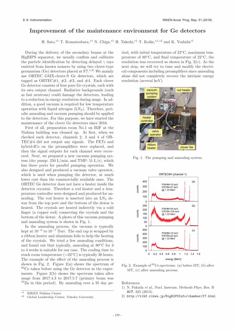
First of all, preparation room No.1 on B2F at theNishina building was cleaned up. At first, when wechecked each detector, channels 2, 3 and 4 of OR-TEC#4 did not output any signals. The FETs andhybrid-ICs on the preamplifiers were replaced, andthen the signal outputs for each channel were recov-ered. Next, we prepared a new vacuum pumping sys-tem (dry pump: 250 L/min, and TMP: 51 L/s), whichhas three ports for parallel pumping operation. Wealso designed and produced a vacuum valve operator,which is used when pumping the detector, at muchlower cost than the commercially available ones. TheORTEC Ge detector does not have a heater inside thedetector cryostat. Therefore a rod heater and a tem-perature controller were designed and produced for an-nealing. The rod heater is inserted into an LN2 de-war from the top port and the bottom of the dewar isheated. The crystals are heated indirectly via a coldfinger (a copper rod) connecting the crystals and thebottom of the dewar. A photo of this vacuum pumpingand annealing system is shown in Fig. 1.
In the annealing process, the vacuum is typicallykept at 10−6 to 10−7 Torr. The end cap is wrapped bya ribbon heater and aluminum foils to help the heatingof the crystals. We tried a few annealing conditions,and found out that typically, annealing at 80◦C for 3to 4 weeks is suitable for our case. The cooling time toreach room temperature (∼22◦C) is typically 30 hours.The example of the effect of the annealing process isshown in Fig. 2. Figure 2(a) shows the spectrum of60Co taken before using the Ge detector in the exper-iments. Figure 2(b) shows the spectrum taken afterusage from 2017.4.3 to 2017.5.7 (primary beam was70Zn in this period). By annealing over a 35 day pe-
∗1 RIKEN Nishina Center∗2 Global Leadership Center, Tohoku University
riod, with initial temperature of 22◦C, maximum tem-perature of 80◦C, and final temperature of 22◦C, theresolution was recovered as shown in Fig. 2(c). As thenext step, we will try to tune and modify the electri-cal components including preamplifiers since annealingalone did not completely recover the intrinsic energyresolution (several keV).
Fig. 1. The pumping and annealing system.
Fig. 2. Example of 60Co spectrum: (a) before MT, (b) after
MT, (c) after annealing process.
References1) N. Fukuda et al., Nucl. Instrum. Methods Phys. Res. B
317, 323 (2013).2) http://ribf.riken.jp/BigRIPSInfo/chamber/f7.html
- 159 -
RIKEN Accel. Prog. Rep. 51 (2018)Ⅱ-9. Instrumentation


![[PPT]New neutron-rich isomers observed among fission …ribf.riken.jp/~seminar/RIBF-NPseminar/NP-Semi_Docu/RIBF... · Web viewPPAC B r with track reconstruction TOF b Plastic scintillation](https://static.fdocument.org/doc/165x107/5af28c857f8b9aa916907e15/pptnew-neutron-rich-isomers-observed-among-fission-ribfrikenjpseminarribf-npseminarnp-semidocuribfweb.jpg)