G.U.N.T. Gerätebau GmbH - Πολυτεχνική Σχολή 169/HM169E.pdf · 4.2.1.1 Preparing...
26
Equipment for Engineering Education Experiment Instructions G.U.N.T. Gerätebau GmbH PO. Box 1125 D-22881 Barsbüttel • Germany Phone (040) 670854-0 Fax (040) 670854-42 HM 169 Drainage and Seepage Tank
Transcript of G.U.N.T. Gerätebau GmbH - Πολυτεχνική Σχολή 169/HM169E.pdf · 4.2.1.1 Preparing...
Equipment for Engineering Education
Experiment Instructions
G.U.N.T. Gerätebau GmbHPO. Box 1125D-22881 Barsbüttel • GermanyPhone (040) 670854-0Fax (040) 670854-42
HM 169 Drainage and Seepage Tank
Experiment Instructions
Publication-No.: 03/99
Please read and follow the instructions before the first installation!
917.000 00 A 169 12
03/9
9
HM 169 Drainage & Seepage TankA
ll rig
hts
rese
rved
G.U
.N.T
. Ger
äteb
au G
mbH
, Bar
sbüt
tel,
Ger
man
y
Table of Contents
1 Introduction. . . . . . . . . . . . . . . . . . . . . . . . . . . . . . . . . . . . . . . 1
2 Description of the Unit . . . . . . . . . . . . . . . . . . . . . . . . . . . . . . 3
2.1 Design . . . . . . . . . . . . . . . . . . . . . . . . . . . . . . . . . . . . . . . . . . . . . . . . 3
2.2 Function . . . . . . . . . . . . . . . . . . . . . . . . . . . . . . . . . . . . . . . . . . . . . . . 4
2.3 Start-up . . . . . . . . . . . . . . . . . . . . . . . . . . . . . . . . . . . . . . . . . . . . . . . 5
2.4 Operation . . . . . . . . . . . . . . . . . . . . . . . . . . . . . . . . . . . . . . . . . . . . . . 5
2.4.1 Filling with Sand . . . . . . . . . . . . . . . . . . . . . . . . . . . . . . . . . . 5
2.4.2 Adjust Water Supply and Overflow . . . . . . . . . . . . . . . . . . . . 6
2.4.3 Filling and Injecting the Dye . . . . . . . . . . . . . . . . . . . . . . . . . 6
2.4.4 Maintenance and Care . . . . . . . . . . . . . . . . . . . . . . . . . . . . . 7
3 Safety Instructions . . . . . . . . . . . . . . . . . . . . . . . . . . . . . . . . . 8
3.1 Safety . . . . . . . . . . . . . . . . . . . . . . . . . . . . . . . . . . . . . . . . . . . . . . . . . 8
3.2 Risk for Unit and Function . . . . . . . . . . . . . . . . . . . . . . . . . . . . . . . . . 8
4 Theoretical Principles . . . . . . . . . . . . . . . . . . . . . . . . . . . . . . 10
4.1 Definitions . . . . . . . . . . . . . . . . . . . . . . . . . . . . . . . . . . . . . . . . . . . . 10
4.1.1 Flow. . . . . . . . . . . . . . . . . . . . . . . . . . . . . . . . . . . . . . . . . . . 10
4.1.2 Flow Field, Flow Lines, Equipotential Lines . . . . . . . . . . . . 10
4.1.3 Seepage Flow . . . . . . . . . . . . . . . . . . . . . . . . . . . . . . . . . . . 12
4.2 Experiments . . . . . . . . . . . . . . . . . . . . . . . . . . . . . . . . . . . . . . . . . . . 14
4.2.1 Streamlines of a Pile Retaining Wall. . . . . . . . . . . . . . . . . . 14
4.2.1.1 Preparing the Experiment . . . . . . . . . . . . . . . . . . . . . . 144.2.1.2 Performing the Experiment . . . . . . . . . . . . . . . . . . . . . 15
4.2.2 Determining a Flow Field . . . . . . . . . . . . . . . . . . . . . . . . . . 15
4.2.3 Pressure distribution with a retaining wall. . . . . . . . . . . . . . 16
4.2.4 Stream Lines through an Earth Bank . . . . . . . . . . . . . . . . . 16
03/9
9
HM 169 Drainage & Seepage TankA
ll rig
hts
rese
rved
G.U
.N.T
. Ger
äteb
au G
mbH
, Bar
sbüt
tel,
Ger
man
y
4.2.5 Pressure Distribution on a Foundation . . . . . . . . . . . . . . . . 16
4.2.6 Pressure on a Bulkhead . . . . . . . . . . . . . . . . . . . . . . . . . . . 17
4.2.6.1 Preparing the Experiment . . . . . . . . . . . . . . . . . . . . . . 174.2.6.2 Performing the Experiment . . . . . . . . . . . . . . . . . . . . . 18
4.2.7 Flow lines of a Drainage Ditch . . . . . . . . . . . . . . . . . . . . . . 19
5 Appendix . . . . . . . . . . . . . . . . . . . . . . . . . . . . . . . . . . . . . . . 20
5.1 Symbols and Units . . . . . . . . . . . . . . . . . . . . . . . . . . . . . . . . . . . . . . 20
5.2 Models . . . . . . . . . . . . . . . . . . . . . . . . . . . . . . . . . . . . . . . . . . . . . . . 21
5.3 Technical Data . . . . . . . . . . . . . . . . . . . . . . . . . . . . . . . . . . . . . . . . . 2203/9
9
HM 169 Drainage & Seepage TankA
ll rig
hts
rese
rved
G.U
.N.T
. Ger
äteb
au G
mbH
, Bar
sbüt
tel,
Ger
man
y
1 Introduction
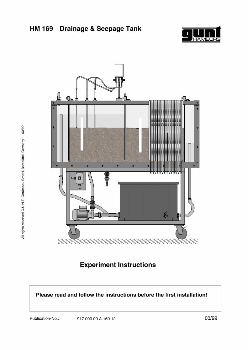
The HM 169 Drainage & Seepage Tank is usedto illustrate two-dimensional flow through perme-able substances. Different models can be placedin the transparent work area.
The unit is equipped with a pump and a tank andcan be operated independent of the water supply.Connection to a power supply is required.
A contrast medium (dye) is injected into the (sand)bed through fine injection nozzles. The transparentfront panel of the work area is ideal for viewing thestreamlines that are produced. The pressure dis-tribution can also be determined via the 14 pres-sure measuring points and manometer board.
The unit includes two adjustable overflow tubes, awater tank and two filter plates, which are used tokeep the sections of the work area free from sand,soil, etc.
A pile retaining wall is included as a model. It isalso possible to determine the pressure distribu-tion at a model foundation and bulkhead.
The unit is designed for use by students in practicallaboratory experiments as well as for demonstra-tion purposes.
Following subjects can be examined using this unit:
- Illustration of flow using permeable substances
- Streamlines under a pile retaining wall
- Streamlines through an earth bank
03/9
9
HM 169 Drainage & Seepage TankA
ll rig
hts
rese
rved
G.U
.N.T
. Ger
äteb
au G
mbH
, Bar
sbüt
tel,
Ger
man
y
1 Introduction 1
- Drainage to an open ditch
- Determination of the pressure distribution at afoundation
- Determination of the pressure distribution at abulkhead
- Determination of flow field in permeable media
03/9
9
HM 169 Drainage & Seepage TankA
ll rig
hts
rese
rved
G.U
.N.T
. Ger
äteb
au G
mbH
, Bar
sbüt
tel,
Ger
man
y
1 Introduction 2
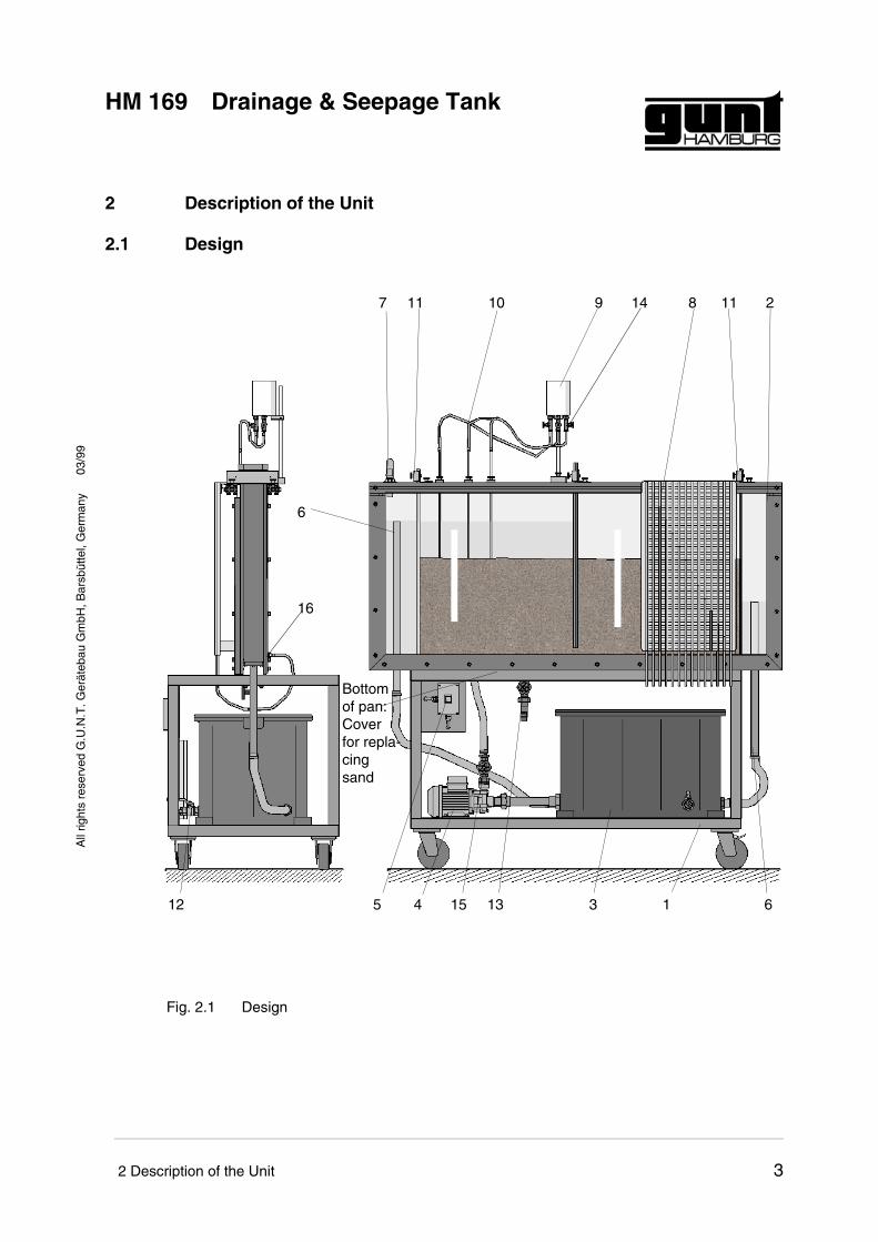
2 Description of the Unit
2.1 Design
7 11 10 9 14 8 11 2
6
16
12 5 4 15 13 3 1 6
Bottomof pan:Coverfor repla-cingsand
Fig. 2.1 Design
03/9
9
HM 169 Drainage & Seepage TankA
ll rig
hts
rese
rved
G.U
.N.T
. Ger
äteb
au G
mbH
, Bar
sbüt
tel,
Ger
man
y
2 Description of the Unit 3
Parts:
• Frame (1)
• Pan with transparent glass plate (2)
• Tank (3)
• Centrifugal pump (4)
• Pump switch (5)
• Overflow tube (6)
• Inlet (7)
• Manometer board (8)
• Supply tank for contrast medium (9)
• Injection lances for contrast medium (10)
• Filter plate (11)
• Discharge cock (12)
• Drainage valve (13)
• Valves for contrast medium (14)
• Inlet valve (15)
• Pressure measuring points (16)
2.2 Function
The centrifugal pump (4) conveys water from thetank (3) through the inlet (7) and into the pan (2).The output can be adjusted using the inlet valve(15). The water level in the pan (2) is adjusted withtwo overflow tubes (6) which return the water to thetank (3). The two filter plates (11) can be used tokeep areas of the pan (2) free of sand or othersubstances.
Fourteen pressure measuring points (16) are loca-ted on the back of the unit, which are connected toa manometer board (8) with piezo tubes to showthe distribution of pressure.
03/9
9
HM 169 Drainage & Seepage TankA
ll rig
hts
rese
rved
G.U
.N.T
. Ger
äteb
au G
mbH
, Bar
sbüt
tel,
Ger
man
y
2 Description of the Unit 4
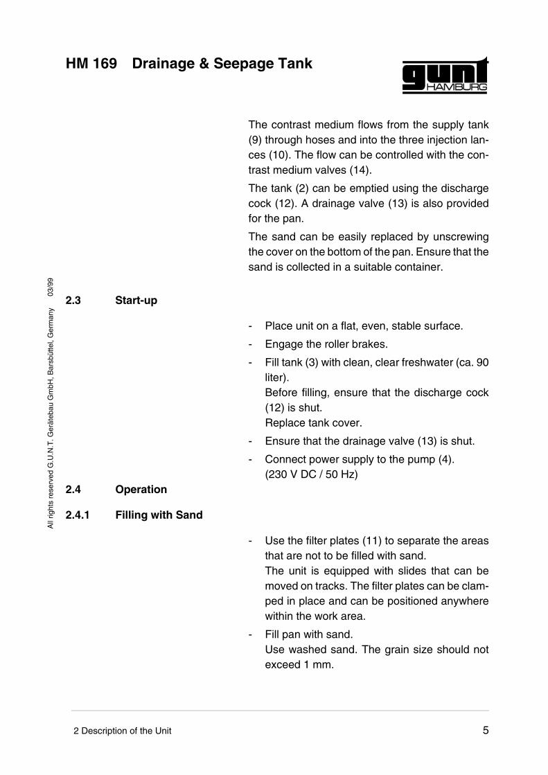
The contrast medium flows from the supply tank(9) through hoses and into the three injection lan-ces (10). The flow can be controlled with the con-trast medium valves (14).
The tank (2) can be emptied using the dischargecock (12). A drainage valve (13) is also providedfor the pan.
The sand can be easily replaced by unscrewingthe cover on the bottom of the pan. Ensure that thesand is collected in a suitable container.
2.3 Start-up
- Place unit on a flat, even, stable surface.
- Engage the roller brakes.
- Fill tank (3) with clean, clear freshwater (ca. 90liter).Before filling, ensure that the discharge cock(12) is shut.Replace tank cover.
- Ensure that the drainage valve (13) is shut.
- Connect power supply to the pump (4).(230 V DC / 50 Hz)
2.4 Operation
2.4.1 Filling with Sand
- Use the filter plates (11) to separate the areasthat are not to be filled with sand.The unit is equipped with slides that can bemoved on tracks. The filter plates can be clam-ped in place and can be positioned anywherewithin the work area.
- Fill pan with sand.Use washed sand. The grain size should notexceed 1 mm.
03/9
9
HM 169 Drainage & Seepage TankA
ll rig
hts
rese
rved
G.U
.N.T
. Ger
äteb
au G
mbH
, Bar
sbüt
tel,
Ger
man
y
2 Description of the Unit 5
2.4.2 Adjust Water Supply and Overflow
- Adjust overflow tubes (6).The overflow tubes can be moved in theirtracks. If they become difficult or stiff to move,turn while pulling.
- Set the pump (4) with the pump switch (5).
- Adjust flow rate with the inlet valve (15).
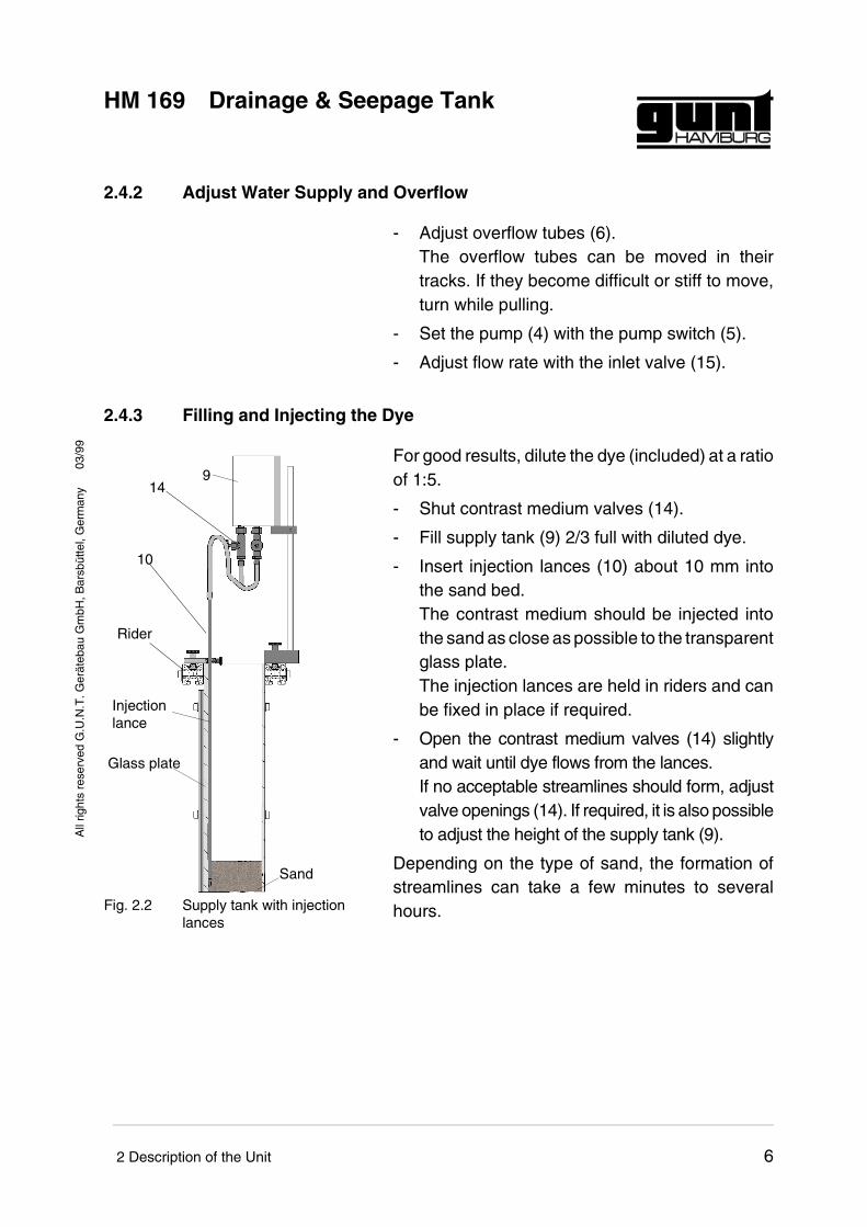
2.4.3 Filling and Injecting the Dye
For good results, dilute the dye (included) at a ratioof 1:5.
- Shut contrast medium valves (14).
- Fill supply tank (9) 2/3 full with diluted dye.
- Insert injection lances (10) about 10 mm intothe sand bed.The contrast medium should be injected intothe sand as close as possible to the transparentglass plate.The injection lances are held in riders and canbe fixed in place if required.
- Open the contrast medium valves (14) slightlyand wait until dye flows from the lances.If no acceptable streamlines should form, adjustvalve openings (14). If required, it is also possibleto adjust the height of the supply tank (9).
Depending on the type of sand, the formation ofstreamlines can take a few minutes to severalhours.
149
10
Rider
Sand
Injectionlance
Glass plate
Fig. 2.2 Supply tank with injectionlances
03/9
9
HM 169 Drainage & Seepage TankA
ll rig
hts
rese
rved
G.U
.N.T
. Ger
äteb
au G
mbH
, Bar
sbüt
tel,
Ger
man
y
2 Description of the Unit 6
2.4.4 Maintenance and Care
- Thought the dye can be washed from textiles,it adheres to aluminium, steel and plastics.Remove dye from the unit as quickly as possi-ble with water.
- Flush injection lances with clear water after use:Remove dye from the supply tank and fill withfresh water. Allow water to flow through thelances until the liquid runs clear.
- After operation has ended, drain water from thepan (2).Pull the overflow tubes (6) downwards until thetop of the tubes is approximately at the samelevel as the base of the pan. Caution! Do notremove overflow tubes completely fromtheir guides.Connect hose to the drainage valve (13) andopen valve. Collect water in a suitable container.
- To avoid the formation of algae, replace waterin the tank (3) regularly.The tank water can be drained via the dischargecock (12).
03/9
9
HM 169 Drainage & Seepage TankA
ll rig
hts
rese
rved
G.U
.N.T
. Ger
äteb
au G
mbH
, Bar
sbüt
tel,
Ger
man
y
2 Description of the Unit 7
3 Safety Instructions
3.1 Safety
- DANGER! Protect pump and electrical linesfrom spraying water!Risk of electrical shock.
3.2 Risk for Unit and Function
- ATTENTION! Operate unit only with super-vision!Possible leaks can result in the risk of overflow.
- ATTENTION! Secure unit against rolling!Engage roller brakes.
- ATTENTION! Never operate pump withoutwater!Dry running can result in damage to the pump.
- ATTENTION! Fill tank with clean water only!Ensure that no foreign matter can enter thetank!Foreign matter can enter the pump and causedamage.
- ATTENTION! Do not use sand with grainsize less than 1 mm! Ensure that no sandcan enter the tank!
- ATTENTION! Store the water-filled test unitin frost-free area!
- ATTENTION! Clean painted parts only withsolvent-free cleaning agents!
03/9
9
HM 169 Drainage & Seepage TankA
ll rig
hts
rese
rved
G.U
.N.T
. Ger
äteb
au G
mbH
, Bar
sbüt
tel,
Ger
man
y
3 Safety Instructions 8
The test unit is designed for operation in dry,covered areas.
03/9
9
HM 169 Drainage & Seepage TankA
ll rig
hts
rese
rved
G.U
.N.T
. Ger
äteb
au G
mbH
, Bar
sbüt
tel,
Ger
man
y
3 Safety Instructions 9
4 Theoretical Principles
4.1 Definitions
4.1.1 Flow
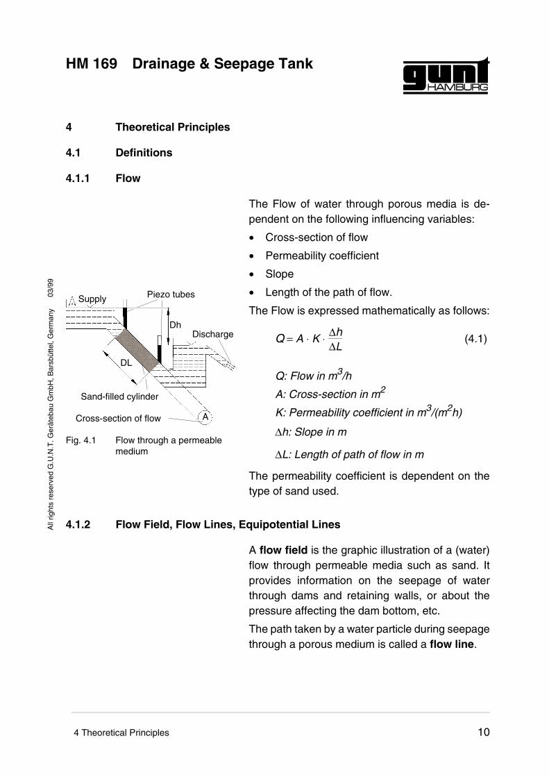
The Flow of water through porous media is de-pendent on the following influencing variables:
• Cross-section of flow
• Permeability coefficient
• Slope
• Length of the path of flow.
The Flow is expressed mathematically as follows:
Q = A ⋅ K ⋅ ∆h∆L
(4.1)
Q: Flow in m3/h
A: Cross-section in m2
K: Permeability coefficient in m3/(m2h)
∆h: Slope in m
∆L: Length of path of flow in m
The permeability coefficient is dependent on thetype of sand used.
4.1.2 Flow Field, Flow Lines, Equipotential Lines
A flow field is the graphic illustration of a (water)flow through permeable media such as sand. Itprovides information on the seepage of waterthrough dams and retaining walls, or about thepressure affecting the dam bottom, etc.
The path taken by a water particle during seepagethrough a porous medium is called a flow line.
DL
Dh
A
Supply
Discharge
Cross-section of flow
Piezo tubes
Sand-filled cylinder
Fig. 4.1 Flow through a permeablemedium
03/9
9
HM 169 Drainage & Seepage TankA
ll rig
hts
rese
rved
G.U
.N.T
. Ger
äteb
au G
mbH
, Bar
sbüt
tel,
Ger
man
y
4 Theoretical Principles 10
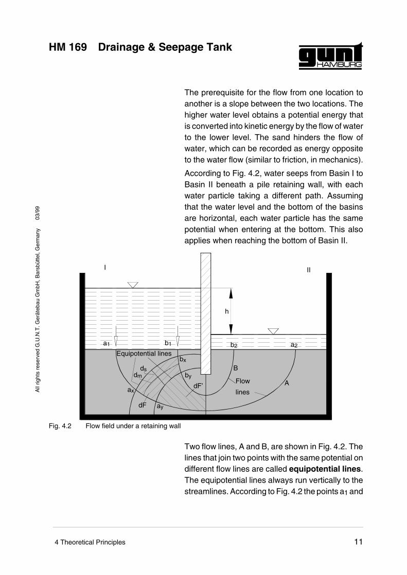
The prerequisite for the flow from one location toanother is a slope between the two locations. Thehigher water level obtains a potential energy thatis converted into kinetic energy by the flow of waterto the lower level. The sand hinders the flow ofwater, which can be recorded as energy oppositeto the water flow (similar to friction, in mechanics).
According to Fig. 4.2, water seeps from Basin I toBasin II beneath a pile retaining wall, with eachwater particle taking a different path. Assumingthat the water level and the bottom of the basinsare horizontal, each water particle has the samepotential when entering at the bottom. This alsoapplies when reaching the bottom of Basin II.
Two flow lines, A and B, are shown in Fig. 4.2. Thelines that join two points with the same potential ondifferent flow lines are called equipotential lines.The equipotential lines always run vertically to thestreamlines. According to Fig. 4.2 the points a1 and
h
I II
a1 b1 b2 a2
A
B
ax
bx
ay
by
Equipotential lines
Flow
lines
dmds
dF
dF’
Fig. 4.2 Flow field under a retaining wall
03/9
9
HM 169 Drainage & Seepage TankA
ll rig
hts
rese
rved
G.U
.N.T
. Ger
äteb
au G
mbH
, Bar
sbüt
tel,
Ger
man
y
4 Theoretical Principles 11
b1 have the same potentials. The same applies toax, bx and ay, by and a2, b2.
The graphic illustration of flow lines and equipoten-tial lines is called the flow field.
The fact that the equipotential lines and the stre-amlines intersect at a right angle is an importantaspect and can be explained visually as follows:
Just as the course of a river normally takes thesteepest route, water flows between equipotentiallines along the so-called maximum gradients. Thegradient is defined as the potential difference be-tween two equipotential lines divided by the inter-val between the two lines. In the case of twoparallel lines the maximum gradient would be on aline that is vertical to the two equipotential lines,that is, at the shortest distance. An infinite numberof adjacent but non-parallel equipotential lineswould result in flow lines as shown in Fig. 4.2.
4.1.3 Seepage Flow
A specific quantity of water which flow from onelocation to another per time unit and length iscalled seepage flow (mathematically designatedas Q, cf. Chap. 4.1.1). The quantity of water thatseeps through the area (limited by the streamlinesa1a2 and b1b2) also passes through the area dF(which is limited by axay and bxby). The seepageflow per length unit is designated here as dq. Thisresults in the following (cf. Fig. 4.2):
dq = K ⋅ dm ⋅ dhds
(4.2)
The decrease in potential dh between two equipo-tential lines is the only unknown value in this case.
If the equipotential lines are selected so that thesurface area dF approximates a square, the di-
03/9
9
HM 169 Drainage & Seepage TankA
ll rig
hts
rese
rved
G.U
.N.T
. Ger
äteb
au G
mbH
, Bar
sbüt
tel,
Ger
man
y
4 Theoretical Principles 12
stance dm is approximately the same as ds. Thisresults in the following:
dq = K ⋅ dh (4.3)
The following applies to dF’:
dq’ = K ⋅ dh’ (4.4)
The Flow through dF’ must be as great as through dF:
dq = dq’ (4.5)
As a consequence of (4.3) and (4.4) it is:
dh = dh’ (4.6)
The strips between two specific flow lines is divi-ded into n number of "rectangles", where the cor-ners form right angles and the sides areapproximately equal. The values for dh must all beequal. Dividing h by n results in dh:
dh = hn
(4.7)
The division into squares is advantageous. It isalso possible to divide them into "normal" rectan-gles if they all have the same dm/ds ratio. Whendm/ds = c this results in the following:
dq = K ⋅ c ⋅ dh (4.8)
dq’ = K ⋅ c ⋅ dh (4.9)
03/9
9
HM 169 Drainage & Seepage TankA
ll rig
hts
rese
rved
G.U
.N.T
. Ger
äteb
au G
mbH
, Bar
sbüt
tel,
Ger
man
y
4 Theoretical Principles 13
4.2 Experiments
4.2.1 Streamlines of a Pile Retaining Wall
4.2.1.1 Preparing the Experiment
- Fill supply tank with contrast medium
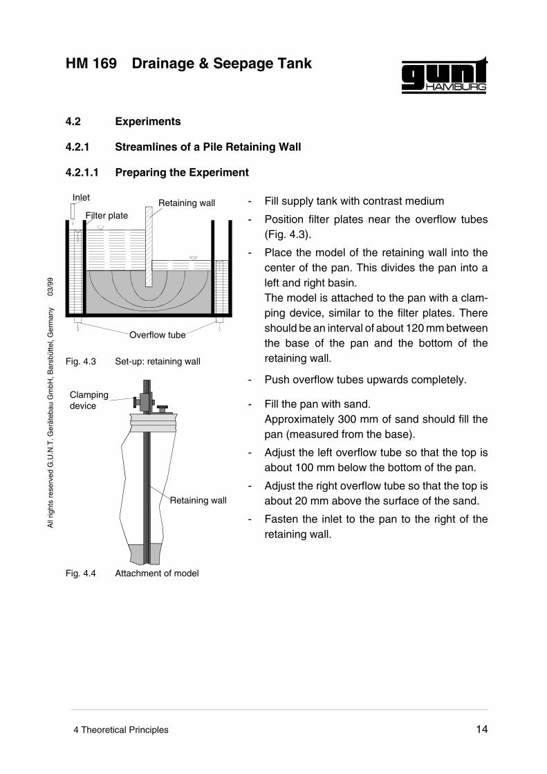
- Position filter plates near the overflow tubes(Fig. 4.3).
- Place the model of the retaining wall into thecenter of the pan. This divides the pan into aleft and right basin.The model is attached to the pan with a clam-ping device, similar to the filter plates. Thereshould be an interval of about 120 mm betweenthe base of the pan and the bottom of theretaining wall.
- Push overflow tubes upwards completely.
- Fill the pan with sand.Approximately 300 mm of sand should fill thepan (measured from the base).
- Adjust the left overflow tube so that the top isabout 100 mm below the bottom of the pan.
- Adjust the right overflow tube so that the top isabout 20 mm above the surface of the sand.
- Fasten the inlet to the pan to the right of theretaining wall.
InletRetaining wall
Overflow tube
Filter plate
Fig. 4.3 Set-up: retaining wall
Clampingdevice
Retaining wall
Fig. 4.4 Attachment of model
03/9
9
HM 169 Drainage & Seepage TankA
ll rig
hts
rese
rved
G.U
.N.T
. Ger
äteb
au G
mbH
, Bar
sbüt
tel,
Ger
man
y
4 Theoretical Principles 14
4.2.1.2 Performing the Experiment
- Start pump and let water flow slowly into theright basin (control with inlet valve).
- When the right basin is full (water is runninginto the overflow tube), fill the left basin.
- Adjust the incoming flow so that the water levelremains constant.
- Smooth any uneven areas on the base bed.
- Insert the injection lances about 10 mm into thesand bed.
- Open the contrast medium valve.If the forming streamlines are too wide, thevalves must be shut slightly. If too little or nodye is released, the valves must be opened.
4.2.2 Determining a Flow Field
The flow lines from the experiment described abo-ve are used to determine a flow field.
- Attach transparent paper to the glass.
- Use a pen to trace the outline of the sand bedand the flow lines on the paper.
- Draw rectangles between the streamline pairs.
- From these rectangles, develop the equipoten-tial lines over the entire flow field. The equipo-tential lines must intersect the flow lines at rightangles.
- Interpolate additional flow lines between theexperimental flow lines so that a rectangularnetwork is created with the equipotential lines.
The seepage rate dq can be determined using theequations from Chap. 4.1.3.
03/9
9
HM 169 Drainage & Seepage TankA
ll rig
hts
rese
rved
G.U
.N.T
. Ger
äteb
au G
mbH
, Bar
sbüt
tel,
Ger
man
y
4 Theoretical Principles 15
4.2.3 Pressure distribution with a retaining wall
The pressure distribution can be illustrated usingthe manometer board. The 14 pressure measuringpoints are distributed and numbered evenly alongthe length of the pan. The example of the retainingwall shows clearly that the pressure decreases inthe direction of flow.
4.2.4 Stream Lines through an Earth Bank
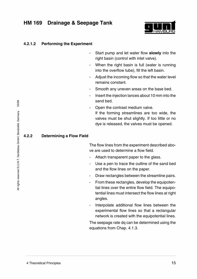
An earth bank is set up in the pan according to Fig.4.5. The injection lances are inserted in the sidefacing the higher water level. The top injectionlance should be positioned as closely as possibleto the water level.
Flow lines similar to Fig. 4.6 will form. The topmostflow line represents the water level in the dam.Care must be taken to ensure that every flow lineis vertical with respect to the surface facing thehigh water (equipotential line).
4.2.5 Pressure Distribution on a Foundation
The preparation of the experiment is similar to thatdescribed in Chap. 4.2.1. In addition, the model"foundation pressure" is then also included in theexperiment set-up according to Fig. 4.6. The topof the right overflow tube should be at the samelevel as the top of the foundation panel. The modelmust lie horizontally on the sand bed and be placeddirectly along the retaining wall. Any gaps betweenthe retaining wall and "foundation" must be sealedwith a thin rubber mat.
It is possible to illustrate the distribution of pressureat the foundation using the model tubes. The retai-ning wall is then set deeper, which shows that thepressure on the foundation is decreasing.
Fig. 4.5 Streamlines through anearth bank
03/9
9
HM 169 Drainage & Seepage TankA
ll rig
hts
rese
rved
G.U
.N.T
. Ger
äteb
au G
mbH
, Bar
sbüt
tel,
Ger
man
y
4 Theoretical Principles 16
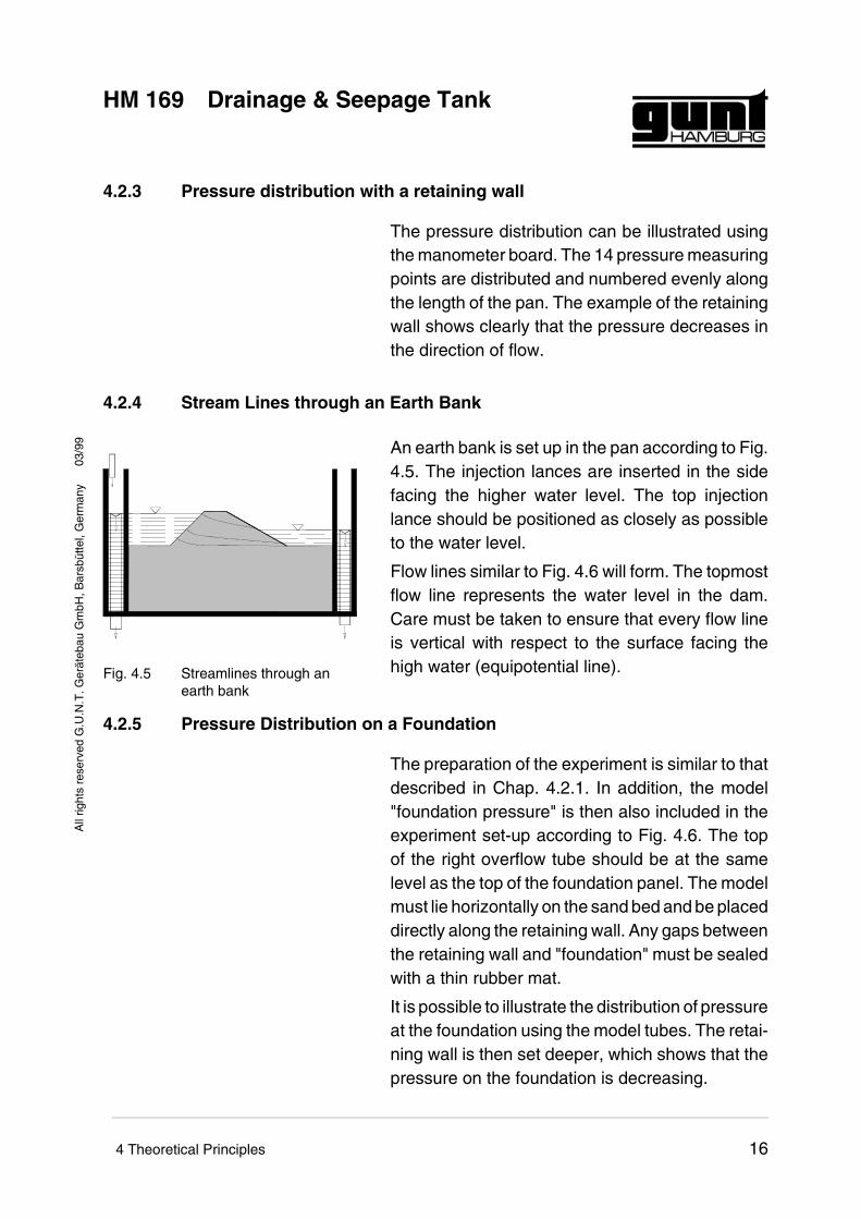
Lengthening or shortening the streamlines has adirect influence on the distribution of pressure.This is often used to reduce pressure on the foun-dation structures.
4.2.6 Pressure on a Bulkhead
4.2.6.1 Preparing the Experiment
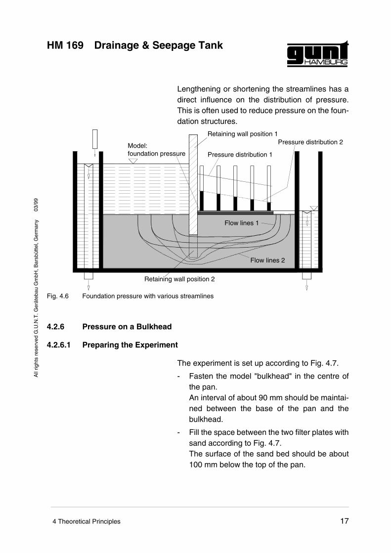
The experiment is set up according to Fig. 4.7.
- Fasten the model "bulkhead" in the centre ofthe pan.An interval of about 90 mm should be maintai-ned between the base of the pan and thebulkhead.
- Fill the space between the two filter plates withsand according to Fig. 4.7.The surface of the sand bed should be about100 mm below the top of the pan.
Retaining wall position 1
Retaining wall position 2
Pressure distribution 1Model:foundation pressure
Pressure distribution 2
Flow lines 1
Flow lines 2
Fig. 4.6 Foundation pressure with various streamlines
03/9
9
HM 169 Drainage & Seepage TankA
ll rig
hts
rese
rved
G.U
.N.T
. Ger
äteb
au G
mbH
, Bar
sbüt
tel,
Ger
man
y
4 Theoretical Principles 17
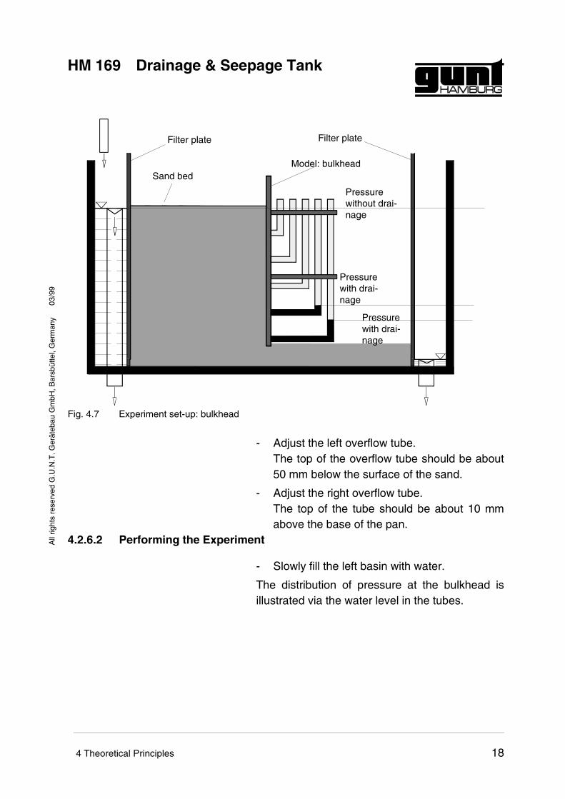
- Adjust the left overflow tube.The top of the overflow tube should be about50 mm below the surface of the sand.
- Adjust the right overflow tube.The top of the tube should be about 10 mmabove the base of the pan.
4.2.6.2 Performing the Experiment
- Slowly fill the left basin with water.
The distribution of pressure at the bulkhead isillustrated via the water level in the tubes.
Pressurewithout drai-nage
Pressurewith drai-nage
Pressurewith drai-nage
Model: bulkhead
Filter plate
Sand bed
Filter plate
Fig. 4.7 Experiment set-up: bulkhead
03/9
9
HM 169 Drainage & Seepage TankA
ll rig
hts
rese
rved
G.U
.N.T
. Ger
äteb
au G
mbH
, Bar
sbüt
tel,
Ger
man
y
4 Theoretical Principles 18
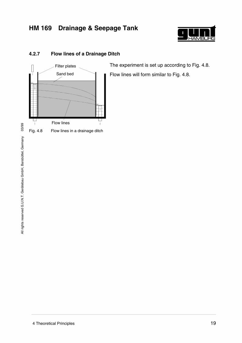
4.2.7 Flow lines of a Drainage Ditch
The experiment is set up according to Fig. 4.8.
Flow lines will form similar to Fig. 4.8.
Filter plates
Sand bed
Flow lines
Fig. 4.8 Flow lines in a drainage ditch03/9
9
HM 169 Drainage & Seepage TankA
ll rig
hts
rese
rved
G.U
.N.T
. Ger
äteb
au G
mbH
, Bar
sbüt
tel,
Ger
man
y
4 Theoretical Principles 19
5 Appendix
5.1 Symbols and Units
A Flow cross-section m3
c Coefficient
dF, dF’ Surface area m2
dh, dh’ Potential decrease m
dm, ds Length m
dq, dq’ Seepage flowm3
m h
h Height m
K Permeability coefficientm3
m2h
Q Throughput m3/h
∆h Slope m
∆L Length of path of flow m
03/9
9
HM 169 Drainage & Seepage TankA
ll rig
hts
rese
rved
G.U
.N.T
. Ger
äteb
au G
mbH
, Bar
sbüt
tel,
Ger
man
y
5 Appendix 20
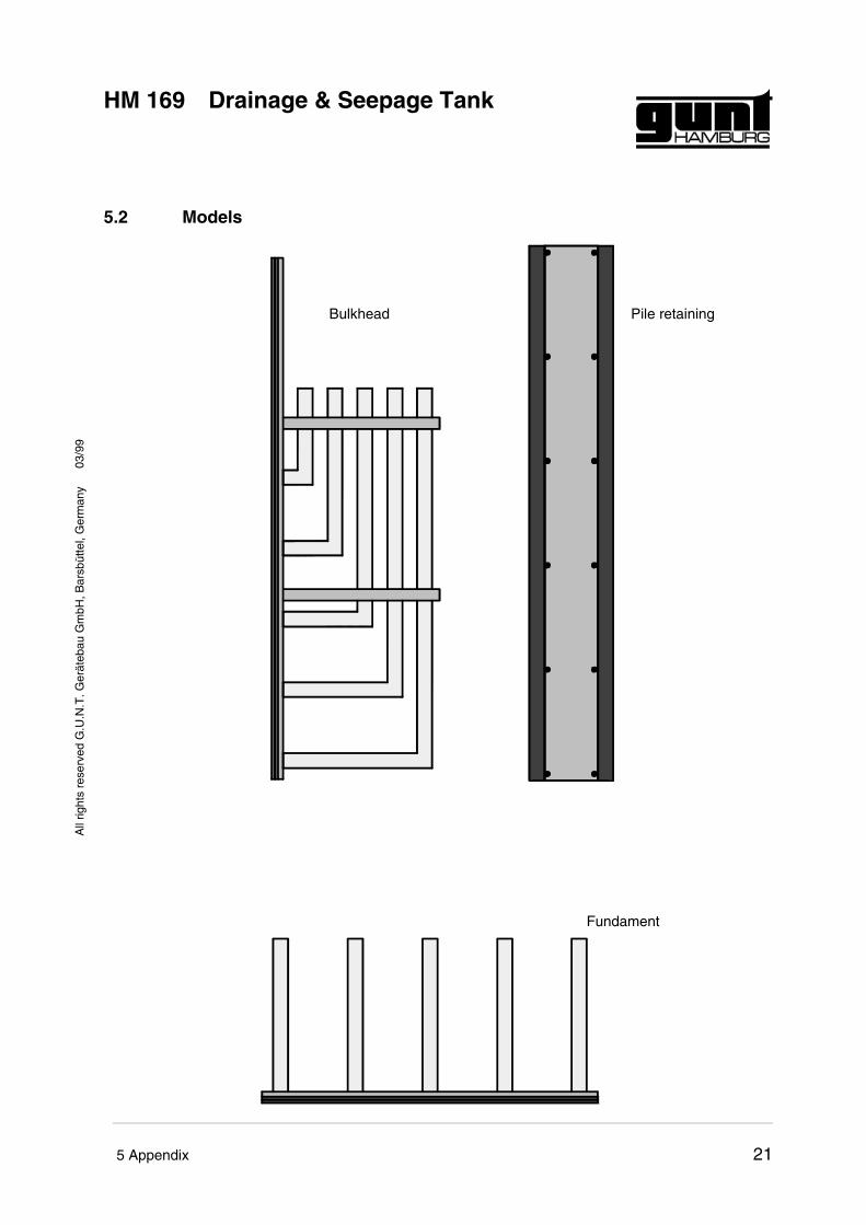
5.2 Models
Bulkhead Pile retaining
Fundament
03/9
9
HM 169 Drainage & Seepage TankA
ll rig
hts
rese
rved
G.U
.N.T
. Ger
äteb
au G
mbH
, Bar
sbüt
tel,
Ger
man
y
5 Appendix 21
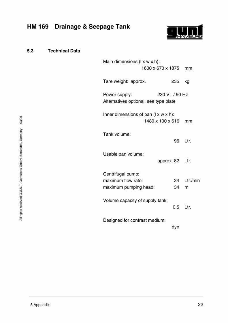
5.3 Technical Data
Main dimensions (l x w x h):1600 x 670 x 1875 mm
Tare weight: approx. 235 kg
Power supply: 230 V~ / 50 HzAlternatives optional, see type plate
Inner dimensions of pan (l x w x h):1480 x 100 x 616 mm
Tank volume:96 Ltr.
Usable pan volume:approx. 82 Ltr.
Centrifugal pump:maximum flow rate: 34 Ltr./minmaximum pumping head: 34 m
Volume capacity of supply tank:0.5 Ltr.
Designed for contrast medium:dye
03/9
9
HM 169 Drainage & Seepage TankA
ll rig
hts
rese
rved
G.U
.N.T
. Ger
äteb
au G
mbH
, Bar
sbüt
tel,
Ger
man
y
5 Appendix 22