GENERAL CATALOGUE CHUBUBIKA CORPORATION · Simple operation, light-weight, corrosion resistant and...
80
GENERAL CATALOGUE CHUBUBIKA CORPORATION WE CONTEMPLATE FLOW PHENOMENA! WE EXPLORE MYSTERY OF SOIL!
Transcript of GENERAL CATALOGUE CHUBUBIKA CORPORATION · Simple operation, light-weight, corrosion resistant and...

GENERAL CATALOGUE
CHUBUBIKA CORPORATION
WE CONTEMPLATE FLOW PHENOMENA!
WE EXPLORE MYSTERY OF SOIL!
ASERIES
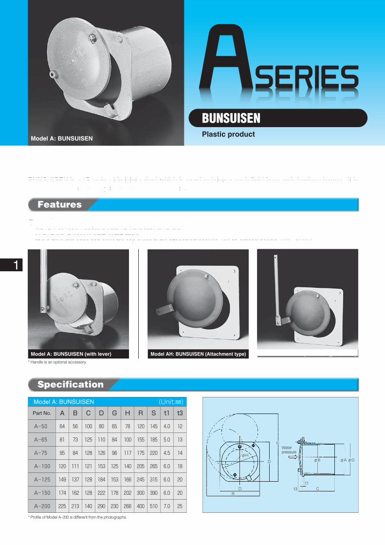
* Handle is an optional accessory.
RD
D
S
φHφB
C
φA φG
t1t3
Water pressure
* Profile of Model A-200 is different from the photographs.
1
BUNSUISENPlastic product
Model A: BUNSUISEN
Specification
Model A: BUNSUISEN� (Unit:㎜)
Part No. A B C D G H R S t1 t3
A-50 64 56 100 80 65 78 120 145 4.0 12
A-65 81 73 125 110 84 100 155 185 5.0 13
A-75 95 84 128 126 96 117 175 220 4.5 14
A-100 120 111 121 153 125 140 205 265 6.0 18
A-125 149 137 128 184 153 166 245 315 6.0 20
A-150 174 162 128 222 178 202 300 390 6.0 20
A-200 225 213 140 290 230 266 400 510 7.0 25
Features
◦��Vinyl chloride pipe can be attached easily to it without adhesive.◦��It is light, corrosion resistant, watertight and easy to handle.◦��It can adjust amount of water intake easily.
*If it is difficult to open and close the cap owing to the attachment position, use an optional handle (500L, 1000L).
BUNSUISEN is a (Simple slide inlet valve) which is used to irrigate each field from an irrigation channel, It is usefully applied especially in new construction work.
Model AH: BUNSUISEN (Attachment type with lever)Model A: BUNSUISEN (with lever) Model AH: BUNSUISEN (Attachment type)
t1t2
Flush bolt
Water pressure
Handle
S
D
CR
φAφB
65
2019181716151413121110987654321
1 2 3 4 5 6 7 8 9 10 11 12 13 14 15
75100125150
7384108137163
115133133133145
Flow rate (Q) ℓ/sec
ValveCategory I.D.
Sketch of measuring device
ValveUnit (mm)
Rectifyer plate L=15m
Channel with variable slope
90° triangular weir
Base length
Water depth (H) cm
φ65 φ75 φ100 φ125 φ150
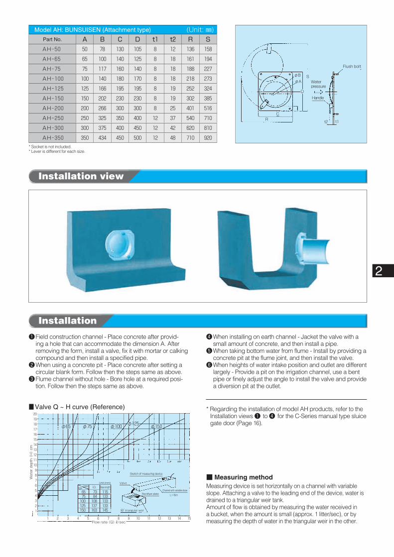
■ Valve Q ~ H curve (Reference)
* Socket is not included.* Lever is different for each size.
2
Installation view
Installation
Model AH: BUNSUISEN (Attachment type)� (Unit: ㎜)Part No. A B C D t1 t2 R SAH-50 50 78 130 105 8 12 136 158
AH-65 65 100 140 125 8 18 161 194
AH-75 75 117 160 140 8 18 188 227
AH-100 100 140 180 170 8 18 218 273
AH-125 125 166 195 195 8 19 252 324
AH-150 150 202 230 230 8 19 302 385
AH-200 200 266 300 300 8 25 401 516
AH-250 250 325 350 400 12 37 540 710
AH-300 300 375 400 450 12 42 620 810
AH-350 350 434 450 500 12 48 710 920
❶�Field construction channel - Place concrete after provid-ing a hole that can accommodate the dimension A. After removing the form, install a valve, fix it with mortar or calking compound and then install a specified pipe.
❷�When using a concrete pit - Place concrete after setting a circular blank form. Follow then the steps same as above.
❸�Flume channel without hole - Bore hole at a required posi-tion. Follow then the steps same as above.
■ Measuring methodMeasuring device is set horizontally on a channel with variable slope. Attaching a valve to the leading end of the device, water is drained to a triangular weir tank.Amount of flow is obtained by measuring the water received in a bucket, when the amount is small (approx. 1 litter/sec), or by measuring the depth of water in the triangular weir in the other.
❹�When installing on earth channel - Jacket the valve with a small amount of concrete, and then install a pipe.
❺�When taking bottom water from flume - Install by providing a concrete pit at the flume joint, and then install the valve.
❻�When heights of water intake position and outlet are different largely - Provide a pit on the irrigation channel, use a bent pipe or finely adjust the angle to install the valve and provide a diversion pit at the outlet.
* Regarding the installation of model AH products, refer to the Installation views ❶ to ❹ for the C-Series manual type sluice gate door (Page 16).
ASERIES
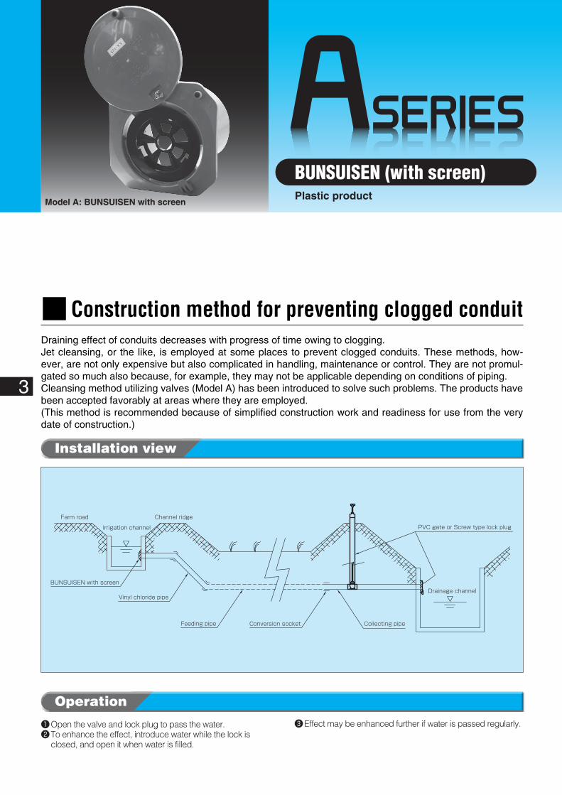
Farm road Channel ridge
Irrigation channel
Vinyl chloride pipe
BUNSUISEN with screen
Feeding pipe Conversion socket
Drainage channel
PVC gate or Screw type lock plug
Collecting pipe
3
BUNSUISEN (with screen)Plastic product
Model A: BUNSUISEN with screen
❶�Open the valve and lock plug to pass the water.❷�To enhance the effect, introduce water while the lock is
closed, and open it when water is filled.
❸�Effect may be enhanced further if water is passed regularly.
Operation
Installation view
■Construction method for preventing clogged conduitDraining effect of conduits decreases with progress of time owing to clogging.Jet cleansing, or the like, is employed at some places to prevent clogged conduits. These methods, how-ever, are not only expensive but also complicated in handling, maintenance or control. They are not promul-gated so much also because, for example, they may not be applicable depending on conditions of piping.Cleansing method utilizing valves (Model A) has been introduced to solve such problems. The products have been accepted favorably at areas where they are employed.(This method is recommended because of simplified construction work and readiness for use from the very date of construction.)
4
ASERIES
5
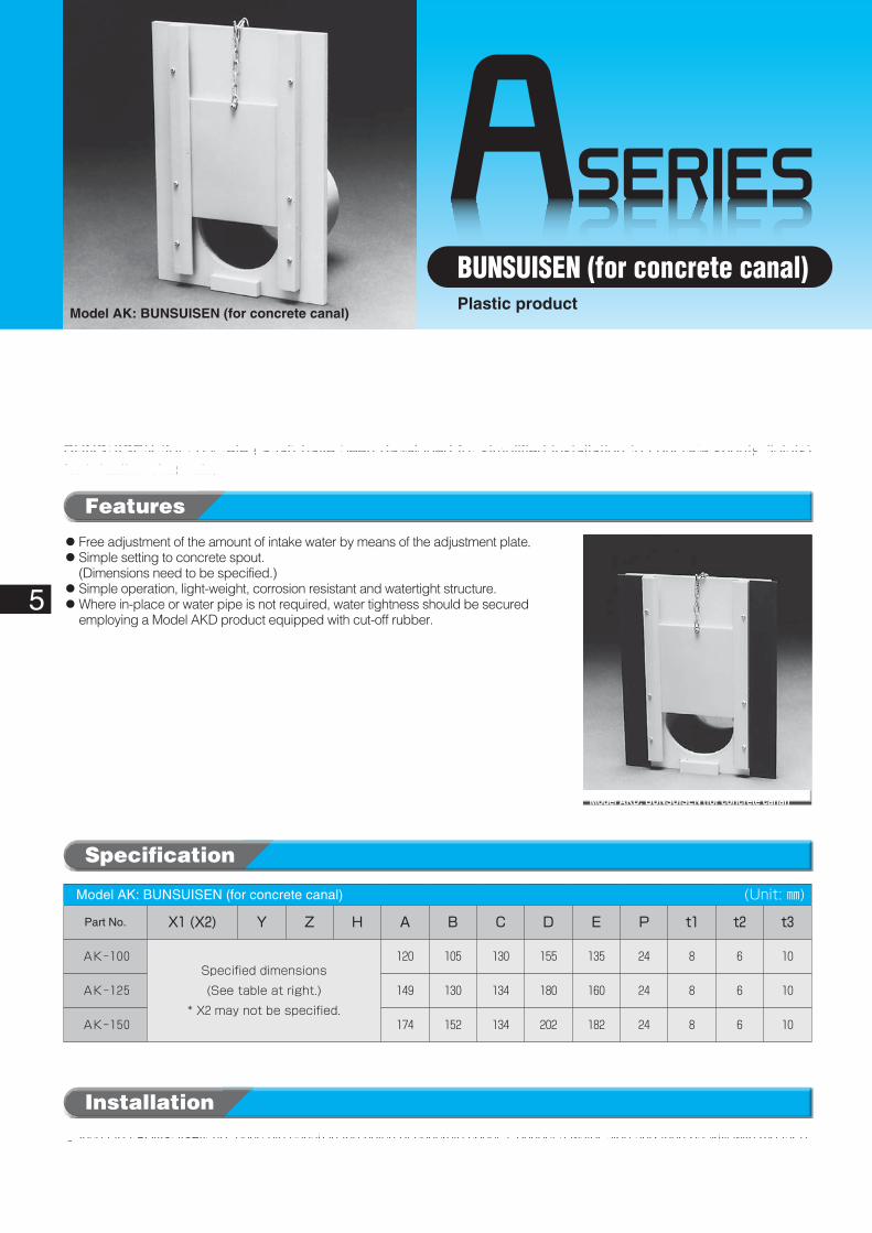
BUNSUISEN (for concrete canal)Plastic product
Model AK: BUNSUISEN (for concrete canal)
Installation
◦��Insert the BUNSUISEN (for concrete canal) in the notch of concrete spout. Connect a water pipe and then backfill with mortar or earth.
Specification
Model AK: BUNSUISEN (for concrete canal)� (Unit: ㎜)
Part No. X1�(X2) Y Z H A B C D E P t1 t2 t3
AK-100Specified dimensions
(See table at right.)
* X2 may not be specified.
120 105 130 155 135 24 8 6 10
AK-125 149 130 134 180 160 24 8 6 10
AK-150 174 152 134 202 182 24 8 6 10
◦��Free adjustment of the amount of intake water by means of the adjustment plate.◦��Simple setting to concrete spout.
(Dimensions need to be specified.)◦��Simple operation, light-weight, corrosion resistant and watertight structure.◦��Where in-place or water pipe is not required, water tightness should be secured
employing a Model AKD product equipped with cut-off rubber.
Features
BUNSUISEN (for concrete canal) have been developed for simplified installation to concrete spouts (joints) for irrigation channels.
Model AKD: BUNSUISEN (for concrete canal)
6
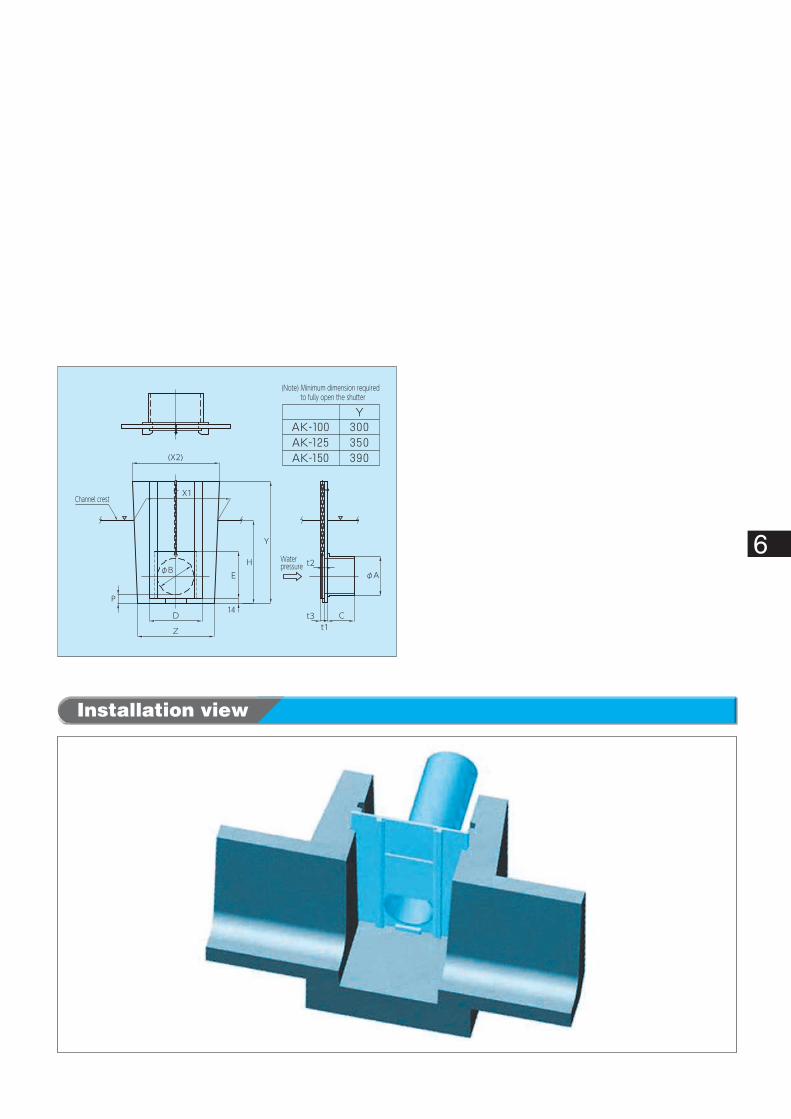
Installation view
14
(Note) Minimum dimension required to fully open the shutter
Channel crest
Waterpressure
(X2)
P
Z
D
φB
X1
EH
Y
t1t3 C
t2φA
BSERIES
* Handle is an optional accessory.
S
R
C
φD
φH
φB φAφE
t1t3
Water pressure
7
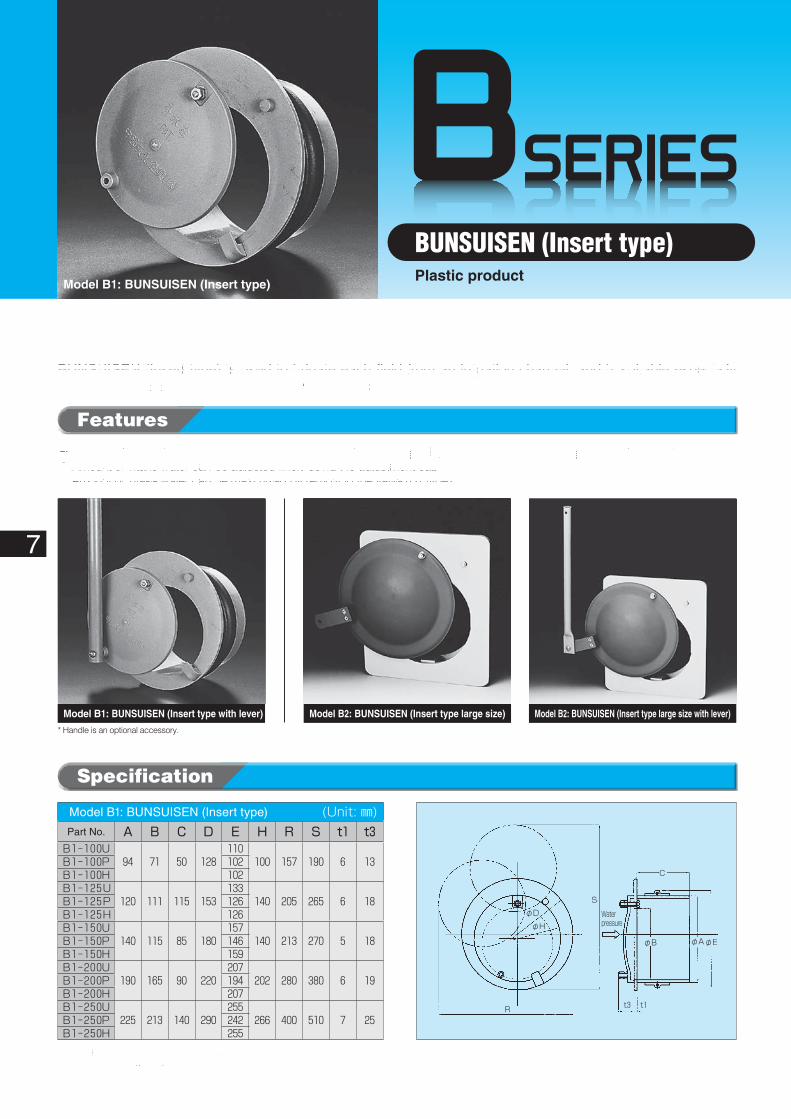
BUNSUISEN (Insert type)Plastic product
Model B1: BUNSUISEN (Insert type)
Specification
Features
◦��BUNSUISEN can be used by simply inserting in the water intake opening (Concrete pipe, Hume pipe, vinyl chloride pipe).◦��Amount of intake water can be adjusted finely using the adjustment cap.◦��Amount of intake water can be maximized by removing the valve (B1 type).
BUNSUISEN (Insert type) is used to irrigate each field from an irrigation channel, and is suitable especially to install on in-place pipe (Hume pipe / vinyl chloride pipe).
* U of part No. means it is suitable to VU pipes, P to VP pipes and H to HP pipes.* Profile of B1-125 flange is square.
Model B1: BUNSUISEN (Insert type)� (Unit: ㎜)Part No. A B C D E H R S t1 t3B1-100U
94 71 50 128110
100 157 190 6 13B1-100P 102B1-100H 102B1-125U
120 111 115 153133
140 205 265 6 18B1-125P 126B1-125H 126B1-150U
140 115 85 180157
140 213 270 5 18B1-150P 146B1-150H 159B1-200U
190 165 90 220207
202 280 380 6 19B1-200P 194B1-200H 207B1-250U
225 213 140 290255
266 400 510 7 25B1-250P 242B1-250H 255
Model B2: BUNSUISEN (Insert type large size with lever)Model B1: BUNSUISEN (Insert type with lever) Model B2: BUNSUISEN (Insert type large size)
φB
φA
φQ
Insert ring
Position fixing screw
C
50
70t1
t2R
D
S Water pressure
Handle
8
Installation
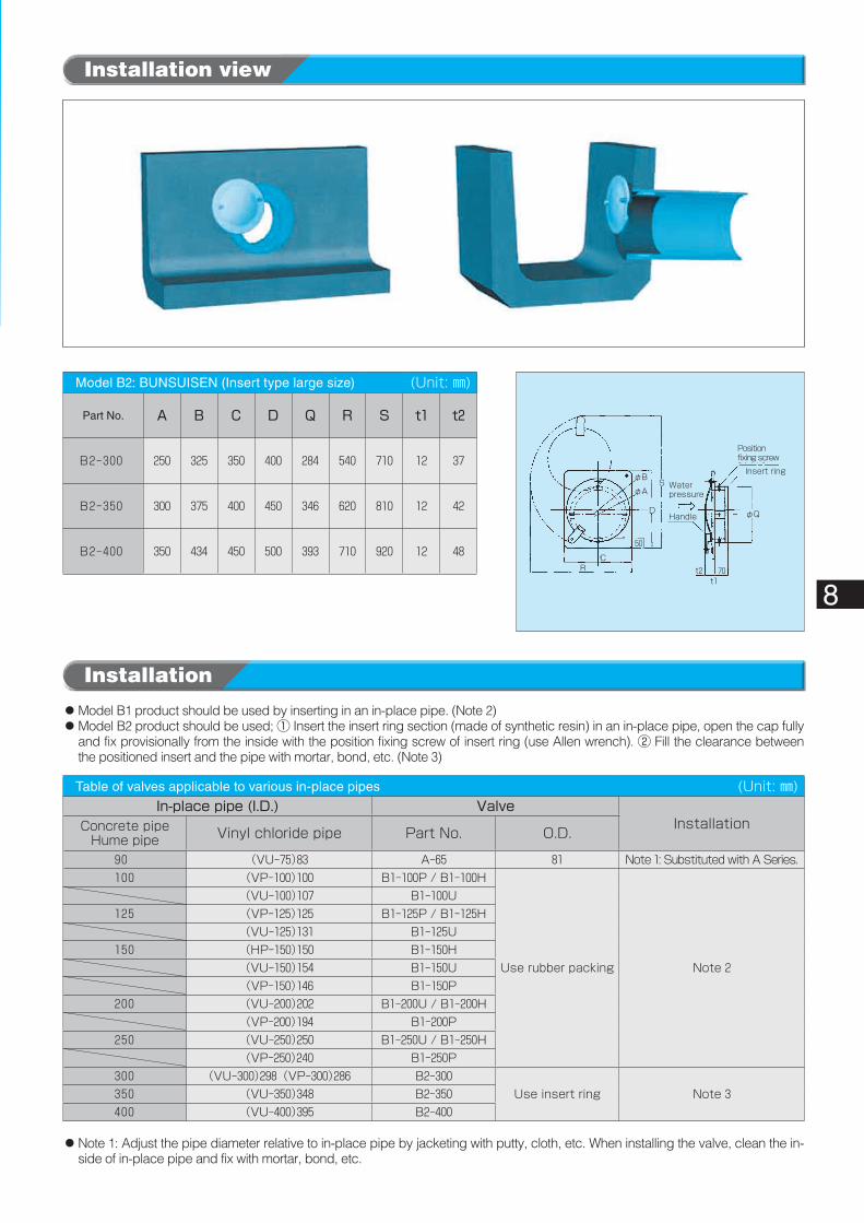
Model B2: BUNSUISEN (Insert type large size)� (Unit: ㎜)
Part No. A B C D Q R S t1 t2
B2-300 250 325 350 400 284 540 710 12 37
B2-350 300 375 400 450 346 620 810 12 42
B2-400 350 434 450 500 393 710 920 12 48
◦��Model B1 product should be used by inserting in an in-place pipe. (Note 2)◦��Model B2 product should be used; ① Insert the insert ring section (made of synthetic resin) in an in-place pipe, open the cap fully
and fix provisionally from the inside with the position fixing screw of insert ring (use Allen wrench). ② Fill the clearance between the positioned insert and the pipe with mortar, bond, etc. (Note 3)
◦��Note 1: Adjust the pipe diameter relative to in-place pipe by jacketing with putty, cloth, etc. When installing the valve, clean the in-side of in-place pipe and fix with mortar, bond, etc.
Table of valves applicable to various in-place pipes� (Unit: ㎜)In-place�pipe�(I.D.) Valve
InstallationConcrete pipeHume pipe Vinyl chloride pipe Part No. O.D.
90 (VU-75)83 A-65 81 Note 1: Substituted with A Series.100 (VP-100)100 B1-100P / B1-100H
Use rubber packing Note 2
(VU-100)107 B1-100U125 (VP-125)125 B1-125P / B1-125H
(VU-125)131 B1-125U150 (HP-150)150 B1-150H
(VU-150)154 B1-150U(VP-150)146 B1-150P
200 (VU-200)202 B1-200U / B1-200H(VP-200)194 B1-200P
250 (VU-250)250 B1-250U / B1-250H(VP-250)240 B1-250P
300 (VU-300)298 (VP-300)286 B2-300Use insert ring Note 3350 (VU-350)348 B2-350
400 (VU-400)395 B2-400
Installation view
CSERIES
4-φRprepared hole
Optional
Waterpressure
D
B
φA
H
P
(L)E
φA
4-φRhole
Waterpressure
Pressure reducing lever
D
B
H
E P
I
* Socket is an optional item. * Pressure reducing lever is used only on sizes larger than 400.
Waterpressure
4-φR holeD
A
K
B
H
E
9
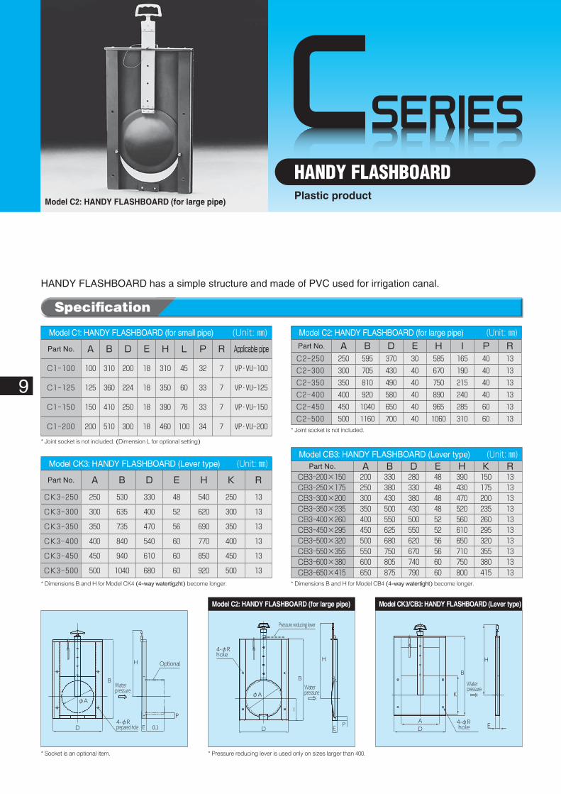
HANDY FLASHBOARDPlastic product
Model C2: HANDY FLASHBOARD (for large pipe)
Model CK3: HANDY FLASHBOARD (Lever type)� (Unit: ㎜)
Part No. A B D E H K R
CK3-250 250 530 330 48 540 250 13
CK3-300 300 635 400 52 620 300 13
CK3-350 350 735 470 56 690 350 13
CK3-400 400 840 540 60 770 400 13
CK3-450 450 940 610 60 850 450 13
CK3-500 500 1040 680 60 920 500 13
Model C1: HANDY FLASHBOARD (for small pipe)� (Unit: ㎜)
Part No. A B D E H L P R Applicable�pipe
C1-100 100 310 200 18 310 45 32 7 VP・VU-100
C1-125 125 360 224 18 350 60 33 7 VP・VU-125
C1-150 150 410 250 18 390 76 33 7 VP・VU-150
C1-200 200 510 300 18 460 100 34 7 VP・VU-200
* Joint socket is not included. (Dimension L for optional setting)
* Dimensions B and H for Model CK4 (4-way watertigzht) become longer.
Model CB3: HANDY FLASHBOARD (Lever type)� (Unit: ㎜)Part No. A B D E H K R
CB3-200×150 200 330 280 48 390 150 13CB3-250×175 250 380 330 48 430 175 13CB3-300×200 300 430 380 48 470 200 13CB3-350×235 350 500 430 48 520 235 13CB3-400×260 400 550 500 52 560 260 13CB3-450×295 450 625 550 52 610 295 13CB3-500×320 500 680 620 56 650 320 13CB3-550×355 550 750 670 56 710 355 13CB3-600×380 600 805 740 60 750 380 13CB3-650×415 650 875 790 60 800 415 13
Model C2: HANDY FLASHBOARD (for large pipe)� (Unit: ㎜)Part No. A B D E H I P RC2-250 250 595 370 30 585 165 40 13C2-300 300 705 430 40 670 190 40 13C2-350 350 810 490 40 750 215 40 13C2-400 400 920 580 40 890 240 40 13C2-450 450 1040 650 40 965 285 60 13C2-500 500 1160 700 40 1060 310 60 13
* Joint socket is not included.
* Dimensions B and H for Model CB4 (4-way watertight) become longer.
Specification
Model C1: HANDY FLASHBOARD (for small pipe) Model C2: HANDY FLASHBOARD (for large pipe) Model CK3/CB3: HANDY FLASHBOARD (Lever type)
HANDY FLASHBOARD has a simple structure and made of PVC used for irrigation canal.
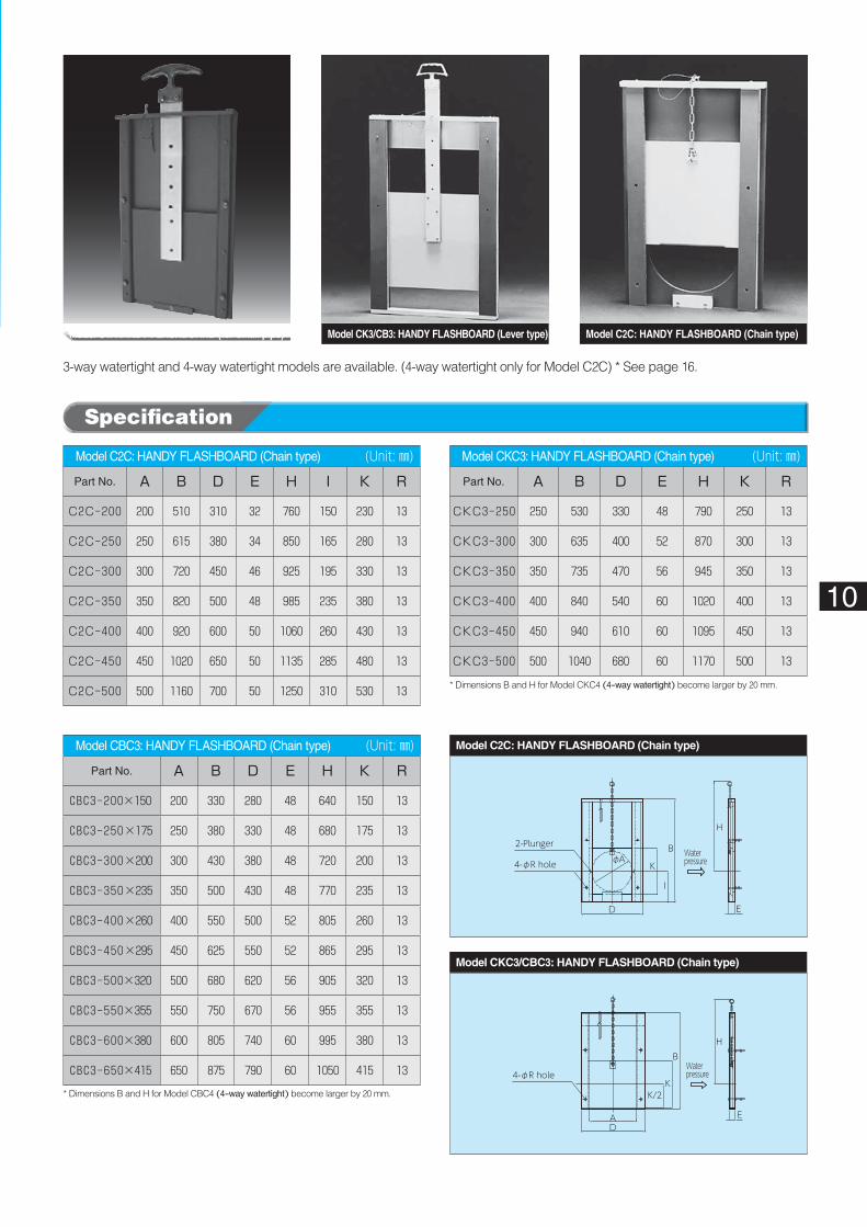
3-way watertight and 4-way watertight models are available. (4-way watertight only for Model C2C) * See page 16.
Waterpressure
DA
K/2K
BH
E
4-φR hole
Waterpressure4-φR hole
2-Plunger
D
φAK
I
B
H
E
10
Model C2C: HANDY FLASHBOARD (Chain type)� (Unit: ㎜)
Part No. A B D E H I K R
C2C-200 200 510 310 32 760 150 230 13
C2C-250 250 615 380 34 850 165 280 13
C2C-300 300 720 450 46 925 195 330 13
C2C-350 350 820 500 48 985 235 380 13
C2C-400 400 920 600 50 1060 260 430 13
C2C-450 450 1020 650 50 1135 285 480 13
C2C-500 500 1160 700 50 1250 310 530 13
Model CKC3: HANDY FLASHBOARD (Chain type)� (Unit: ㎜)
Part No. A B D E H K R
CKC3-250 250 530 330 48 790 250 13
CKC3-300 300 635 400 52 870 300 13
CKC3-350 350 735 470 56 945 350 13
CKC3-400 400 840 540 60 1020 400 13
CKC3-450 450 940 610 60 1095 450 13
CKC3-500 500 1040 680 60 1170 500 13
* Dimensions B and H for Model CKC4 (4-way watertight) become larger by 20 mm.
Model CBC3: HANDY FLASHBOARD (Chain type)� (Unit: ㎜)
Part No. A B D E H K R
CBC3-200×150 200 330 280 48 640 150 13
CBC3-250×175 250 380 330 48 680 175 13
CBC3-300×200 300 430 380 48 720 200 13
CBC3-350×235 350 500 430 48 770 235 13
CBC3-400×260 400 550 500 52 805 260 13
CBC3-450×295 450 625 550 52 865 295 13
CBC3-500×320 500 680 620 56 905 320 13
CBC3-550×355 550 750 670 56 955 355 13
CBC3-600×380 600 805 740 60 995 380 13
CBC3-650×415 650 875 790 60 1050 415 13
* Dimensions B and H for Model CBC4 (4-way watertight) become larger by 20 mm.
Specification
Model C1: HANDY FLASHBOARD (for small pipe) Model C2C: HANDY FLASHBOARD (Chain type)Model CK3/CB3: HANDY FLASHBOARD (Lever type)
Model CKC3/CBC3: HANDY FLASHBOARD (Chain type)
Model C2C: HANDY FLASHBOARD (Chain type)
CSERIES
Waterpressure
80
H
B C
φA
Waterpressure
80
H
B C
φA
Waterpressure
B C
H
80
φA
11
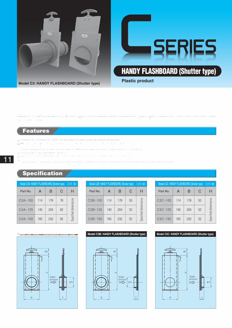
HANDY FLASHBOARD (Shutter type)Plastic product
Model C3: HANDY FLASHBOARD (Shutter type)
Model C3A: HANDY FLASHBOARD (Shutter type)� (Unit: ㎜)
Part No. A B C H
C3A-100 114 178 78
Spec
ified d
imen
sions
C3A-125 140 204 82
C3A-150 165 232 82
Model C3B: HANDY FLASHBOARD (Shutter type)� (Unit: ㎜)
Part No. A B C H
C3B-100 114 178 50
Spec
ified d
imen
sions
C3B-125 140 204 52
C3B-150 165 232 52
Model C3C: HANDY FLASHBOARD (Shutter type)� (Unit: ㎜)
Part No. A B C H
C3C-100 114 178 50
Spec
ified d
imen
sions
C3C-125 140 204 52
C3C-150 165 232 52
Specification
Features
◦��There are 3 types of gate according to direction of water pressure.◦��The length of body need to be specified according to the height of channel.◦��It can adjust the length of conduit in tune with canal width. (Main unit VP·VU joint)◦��Door part can be taken apart.◦��Please confirm that the direction of water pressure is defined for each types.◦��Note that It flow over from the top of gate in case of water level become higher than the length of body.
HANDY FLASHBOARD (Shutter type) is versatile and reasonable price gate made of PVC used for inlet port of paddy field.
* Conduit pipe is an optional item. * Contact us in case of other size.
Model C3A: HANDY FLASHBOARD (Shutter type) Model C3B: HANDY FLASHBOARD (Shutter type) Model C3C: HANDY FLASHBOARD (Shutter type)
CSERIES
4-M8Screw anchor
H
L
43
B
DA
50 5018
Waterpressure
12
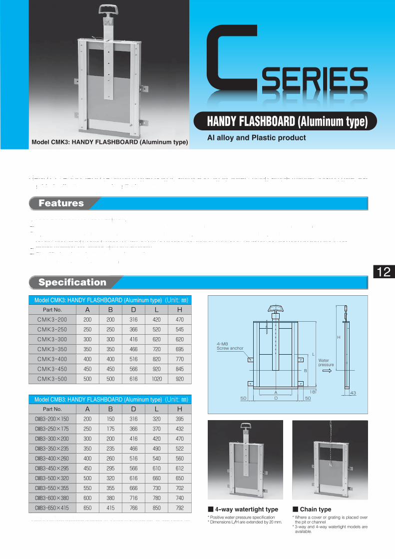
HANDY FLASHBOARD (Aluminum type)Al alloy and Plastic product
Model CMK3: HANDY FLASHBOARD (Aluminum type)
Specification
Features
◦Light and highly corrosion resistant.◦Parts of frame and handle are made of aluminum alloy while synthetic alloy is used for the cut-off face and the shutter.◦Synthetic resin used for the cut-off section enhances water tightness and provides stable operation.◦Shutter and sliding surface made of synthetic resin reduce the friction resistance, allowing opening and closing effortlessly.◦Height of mounting anchor plate is adjustable.◦Simplified and sturdy structure and operation.◦3-way and 4-way models are provided.
HANDY FLASHBOARD (Aluminum type) is light, sturdy and highly water cutting simple manual hoisting gate, as-sembled with aluminum and synthetic resin.
* 4-way models are also produced.* It may not be used depending on properties of water such as sewage, hot spring water, etc.
Model CMK3: HANDY FLASHBOARD (Aluminum type)� (Unit: ㎜)Part No. A B D L H
CMK3-200 200 200 316 420 470
CMK3-250 250 250 366 520 545
CMK3-300 300 300 416 620 620
CMK3-350 350 350 466 720 695
CMK3-400 400 400 516 820 770
CMK3-450 450 450 566 920 845
CMK3-500 500 500 616 1020 920
Model CMB3: HANDY FLASHBOARD (Aluminum type)� (Unit: ㎜)Part No. A B D L H
CMB3-200×150 200 150 316 320 395
CMB3-250×175 250 175 366 370 432
CMB3-300×200 300 200 416 420 470
CMB3-350×235 350 235 466 490 522
CMB3-400×260 400 260 516 540 560
CMB3-450×295 450 295 566 610 612
CMB3-500×320 500 320 616 660 650
CMB3-550×355 550 355 666 730 702
CMB3-600×380 600 380 716 780 740
CMB3-650×415 650 415 766 850 792 ■ 4-way watertight type* Positive water pressure specification* Dimensions L/H are extended by 20 mm.
■ Chain type* Where a cover or grating is placed over
the pit or channel* 3-way and 4-way watertight models are
available.
CSERIES
E
t
E
L
H
B
A
D
Water pressure
13
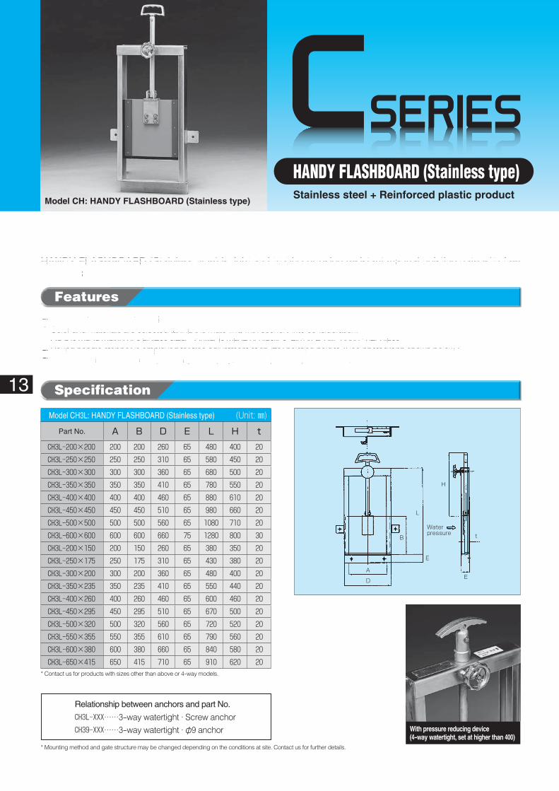
HANDY FLASHBOARD (Stainless type)Stainless steel + Reinforced plastic product
Model CH: HANDY FLASHBOARD (Stainless type)
Specification
Features
◦Light and highly corrosion resistant.◦Color and materials are selected taking the matching with scenery into consideration.◦Gate is made mainly of stainless steel. Shutter is made of plastics reinforced with long fiber glass.◦Round handle stopper is employed for free adjustment of shutter hoisting height. (See photograph shown below.)◦Detachable round handle stopper may be employed as an option, to prevent abuse.
HANDY FLASHBOARD (Stainless type) is light and highly corrosion resistant manual hoisting gate with free adjustment of hoist amount.
Model CH3L: HANDY FLASHBOARD (Stainless type)� (Unit: ㎜)
Part No. A B D E L H tCH3L-200×200 200 200 260 65 480 400 20CH3L-250×250 250 250 310 65 580 450 20CH3L-300×300 300 300 360 65 680 500 20CH3L-350×350 350 350 410 65 780 550 20CH3L-400×400 400 400 460 65 880 610 20CH3L-450×450 450 450 510 65 980 660 20CH3L-500×500 500 500 560 65 1080 710 20CH3L-600×600 600 600 660 75 1280 800 30CH3L-200×150 200 150 260 65 380 350 20CH3L-250×175 250 175 310 65 430 380 20CH3L-300×200 300 200 360 65 480 400 20CH3L-350×235 350 235 410 65 550 440 20CH3L-400×260 400 260 460 65 600 460 20CH3L-450×295 450 295 510 65 670 500 20CH3L-500×320 500 320 560 65 720 520 20CH3L-550×355 550 355 610 65 790 560 20CH3L-600×380 600 380 660 65 840 580 20CH3L-650×415 650 415 710 65 910 620 20
* Contact us for products with sizes other than above or 4-way models.
* Mounting method and gate structure may be changed depending on the conditions at site. Contact us for further details.
Relationship between anchors and part No.
CH3L-XXX……3-way watertight · Screw anchorCH39-XXX……3-way watertight · φ9 anchor With pressure reducing device
(4-way watertight, set at higher than 400)
CSERIES
4-M8Screw anchor
OPEN ROCK
Waterpressure
Fixing anchor type(A type)
Length ofhandle:H(Normal)
E
G
F
D
BC
33221
Opening:φA
Extensionhandle:700or1000
14
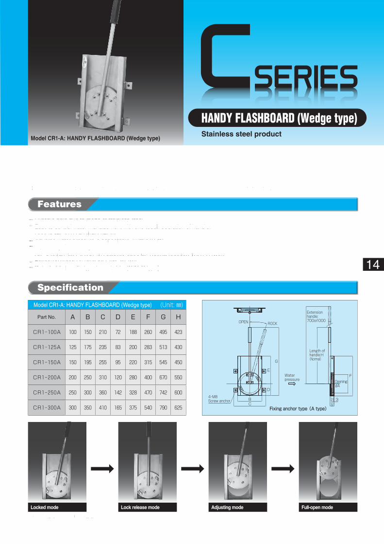
HANDY FLASHBOARD (Wedge type)Stainless steel product
Model CR1-A: HANDY FLASHBOARD (Wedge type)
Specification
◦��Durable gate due to made of stainless steel.◦��Easy to control water-management with one-touch operation of handle.◦��Door is set up on arbitrary height.◦��Adverse water pressure is acceptable. (within 0.5m)◦��Water-stop GUM is replaceable.◦��As for angle type ,It can be installed easily with screw anchors. (CR1-A type)◦��Extension handle is available. (within 1m)◦��Detachable handle type is available. (CR1-C type)
Features
HANDY FLASHBOARD (Wedge type) is simple structure gate made mainly of stainless steel.
* The photograph is for embedding type.
Model CR1-A: HANDY FLASHBOARD (Wedge type)� (Unit: ㎜)
Part No. A B C D E F G H
CR1-100A 100 150 210 72 188 260 495 423
CR1-125A 125 175 235 83 200 283 513 430
CR1-150A 150 195 255 95 220 315 545 450
CR1-200A 200 250 310 120 280 400 670 550
CR1-250A 250 300 360 142 328 470 742 600
CR1-300A 300 350 410 165 375 540 790 625
Locked mode Lock release mode Full-open modeAdjusting mode
CSERIES
A:Effective width
Bore height
Dimension X
B:Effective height
Waterpressure
500
10°
350
15
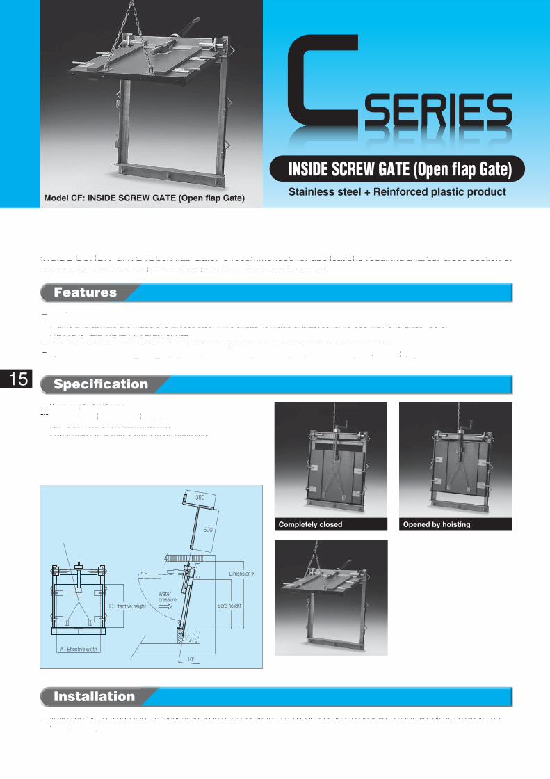
INSIDE SCREW GATE (Open flap Gate)Stainless steel + Reinforced plastic product
Model CF: INSIDE SCREW GATE (Open flap Gate)
Specification
Features
◦Light and highly resistant to corrosion.◦Frame and spindle are made of stainless steel while shutter is made of plastics reinforced with long glass fibers.◦Handle is detachable to prevent abuse.◦Door can be opened completely thanks to the combination of special spindle structure and chain.◦Where a cover is used (grating, etc.), the spindle will not protrude upward when it is opened completely.
INSIDE SCREW GATE (Open flap Gate) is recommended for applications requiring a larger cross-section of opening in a limited mounting height condition. (Hoisting flap type)
Installation
◦��Weld and fix the product to the foundation concrete tilted by 10°, and pour secondary concrete to cut water off at the sides and lower frames.
❶3-way watertight type.❷��Effective width x dam-up height
Up to 600 mm x 600 mm maximumDimensions A, B and X need to be specified.
Completely opened
Opened by hoistingCompletely closed
Channel bottom
Shutter
Overflow
Water level
Flow
Water level
Flow
Shutter
Doorstop
Conduit
Pit bottom
Sluice gate door
Calking compound
Sluice gate door
Joint filler
A
D
E
J
B
L
E
H
t1(Lower shutter thickness)t2(Upper shutter thickness)
80
Water pressure
Upper shutter heightB/2+10
4-φ13 drill
Lower shutter heightB/2+10
16
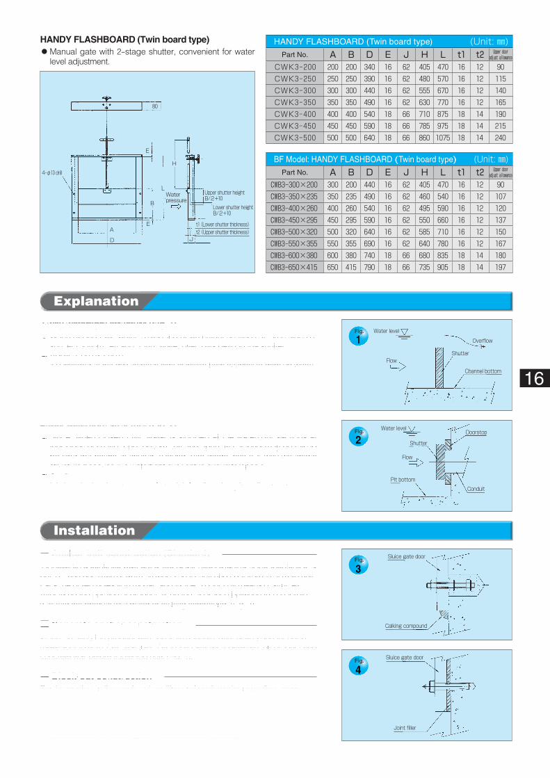
HANDY FLASHBOARD (Twin board type)◦��Manual gate with 2-stage shutter, convenient for water
level adjustment.
HANDY FLASHBOARD (Twin board type)� (Unit: ㎜)Part No. A B D E J H L t1 t2 Upper door
adjust allowance
CWK3-200 200 200 340 16 62 405 470 16 12 90CWK3-250 250 250 390 16 62 480 570 16 12 115CWK3-300 300 300 440 16 62 555 670 16 12 140CWK3-350 350 350 490 16 62 630 770 16 12 165CWK3-400 400 400 540 18 66 710 875 18 14 190CWK3-450 450 450 590 18 66 785 975 18 14 215CWK3-500 500 500 640 18 66 860 1075 18 14 240
BF Model: HANDY FLASHBOARD (Twin board type)� (Unit: ㎜)Part No. A B D E J H L t1 t2 Upper door
adjust allowance
CWB3-300×200 300 200 440 16 62 405 470 16 12 90CWB3-350×235 350 235 490 16 62 460 540 16 12 107CWB3-400×260 400 260 540 16 62 495 590 16 12 120CWB3-450×295 450 295 590 16 62 550 660 16 12 137CWB3-500×320 500 320 640 16 62 585 710 16 12 150CWB3-550×355 550 355 690 16 62 640 780 16 12 167CWB3-600×380 600 380 740 18 66 680 835 18 14 180CWB3-650×415 650 415 790 18 66 735 905 18 14 197
Installation
Explanation
3-way watertight structure (Fig. 1)◦��When closed fully, water is stopped at watertight sections at three sides of
shutter (bottom, left and right). Water overflows beyond the shutter.◦��Application example
It is installed at the downstream side of intake from channel to dam up water.
* Concrete anchors are not included. Procure at site referring to the dimension R.
4-way watertight structure (Fig. 2)◦��Since, when closed fully, water is stopped at the watertight sections at
four sides of shutter (top, bottom, left and right), water level may be raised beyond the height of shutter. (Round type model has a 4-way watertight structure because it is watertight over entire circumference.)
◦��Application example It is installed at the entrance of conduit for diversion pit to divert water.
■ Anchor bolt construction (Standard)To install on a concrete wall, drill a little larger holes aligning to the positions of a pair of flash bolts (M6 or M10) provided on the left and right frames of main unit.Pack the drilled holes with mortar, and fix the product by means of strut, etc.After fixing the position of product, fill up the clearance between the concrete wall and the product with motor or calking compound. (Fig. 3)
■ Concrete anchor constructionWhen installing the product with concrete anchors, after drilling anchor holes, make sure to fill rubber type joint filler in the clearance between the product and concrete wall before tightening nuts (Fig. 4).
■ Block-out constructionSet the product in the block-out position and pack mortar or sealing agent.
CSERIES
17
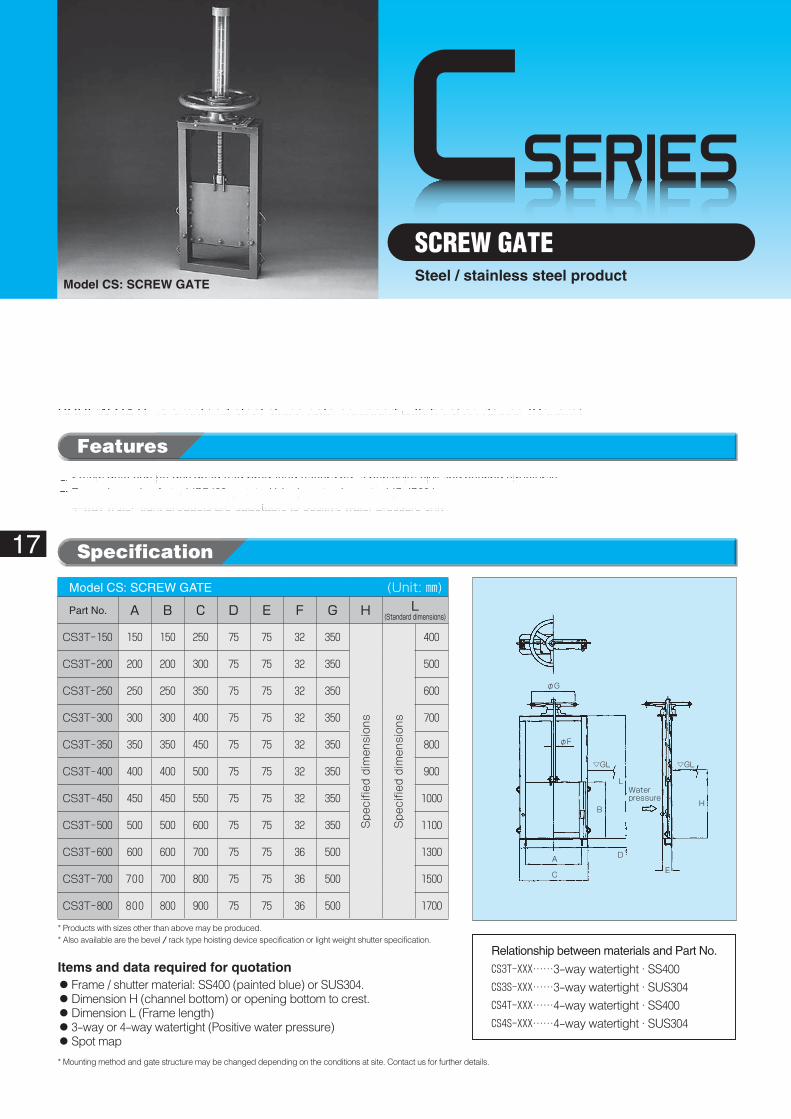
SCREW GATESteel / stainless steel product
Model CS: SCREW GATE
φG
φF
B
A D
E
H
▽GL ▽GL
L
C
Water pressure
Specification
Features
◦Screw gate can be designed and produced according to particular civil engineering structures.◦Frame is made of steel (SS400, painted blue) or stainless steel (SUS304).◦4-way water-tight products are adaptable to positive water pressure only.
SCREW GATE is simplified steel sluice gate equipped with hoisting device (Square).
Model CS: SCREW GATE� (Unit: ㎜)
Part No. A B C D E F G H L(Standard�dimensions)
CS3T-150 150 150 250 75 75 32 350
Spe
cifie
d dimen
sion
s
Spe
cifie
d dimen
sion
s
400
CS3T-200 200 200 300 75 75 32 350 500
CS3T-250 250 250 350 75 75 32 350 600
CS3T-300 300 300 400 75 75 32 350 700
CS3T-350 350 350 450 75 75 32 350 800
CS3T-400 400 400 500 75 75 32 350 900
CS3T-450 450 450 550 75 75 32 350 1000
CS3T-500 500 500 600 75 75 32 350 1100
CS3T-600 600 600 700 75 75 36 500 1300
CS3T-700 700 700 800 75 75 36 500 1500
CS3T-800 800 800 900 75 75 36 500 1700
* Products with sizes other than above may be produced.* Also available are the bevel / rack type hoisting device specification or light weight shutter specification.
* Mounting method and gate structure may be changed depending on the conditions at site. Contact us for further details.
Items and data required for quotation◦Frame / shutter material: SS400 (painted blue) or SUS304.◦Dimension H (channel bottom) or opening bottom to crest.◦Dimension L (Frame length)◦3-way or 4-way watertight (Positive water pressure)◦Spot map
Relationship between materials and Part No.
CS3T-XXX……3-way watertight · SS400CS3S-XXX……3-way watertight · SUS304CS4T-XXX……4-way watertight · SS400CS4S-XXX……4-way watertight · SUS304
CSERIES
18
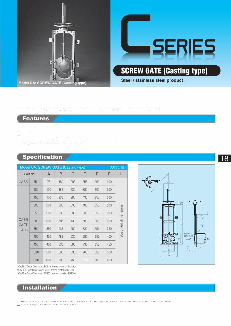
SCREW GATE (Casting type)Steel / stainless steel product
Model CA: SCREW GATE (Casting type)
Waterpressure
φA
φE
100
L
F
DCB
Specification
Features
◦Shutter and doorstop are made of casting FC200 or SCS13.◦ It can be installed easily using screw anchors.◦Frame is made of steel (SS400, painted blue) or stainless steel (SUS304).◦Water pressure direction is limited to positive only.◦��Inside screw specification is also provided.
SCREW GATE (Casting type) is round sluice gate equipped with hoisting device.
Model CA: SCREW GATE (Casting type)� (Unit: ㎜)
Part No. A B C D E F L
CASS 75 75 160 205 355 350 300
Spe
cifie
d dimen
sion
s
CASS
CAFT
CAFS
100 100 186 230 380 350 300
150 150 236 280 430 350 300
200 200 286 330 480 350 300
250 250 336 380 530 350 300
300 300 386 430 580 350 300
350 350 436 480 630 350 350
400 400 486 530 680 350 400
450 450 536 580 730 350 450
500 500 586 630 780 350 500
600 600 686 760 910 500 600
* CASS / Door·Door-stop:SCS13 frame material: SUS304* CAFT / Door·Door-stop:FC200 frame material: SS400* CAFS / Door·Door-stop:FC200 frame material: SUS304
Installation
❶Stick the attached cut-off rubber to the doorstop.❷Align the bottom of opening on the doorstop to the internal bottom of pipe, and correct the tilt of gate.❸Drive screw anchors in to fix the gate.
CSERIES
(Effective height)
A(Effective width)
D(Frame width)
For weldingφ9 anchor
(Frame height)
Waterpressure (Opening bottom~ Crest)
φG100
L
GL GL
B
E
J
H
19
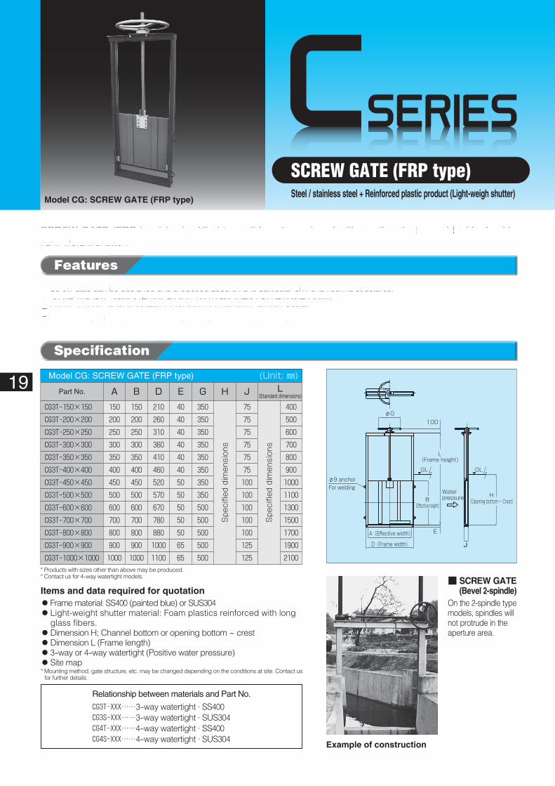
SCREW GATE (FRP type)Steel / stainless steel + Reinforced plastic product (Light-weigh shutter)
Model CG: SCREW GATE (FRP type)
Specification
Features
◦Screw gate can be designed and produced according to particular civil engineering structures.◦Shutter made of plastics reinforced with long glass fibers can be hoisted lightly.◦Frame is made of steel (SS400, painted blue) or stainless steel (SUS304).◦4-way watertight models are adapted to positive water pressure only.
SCREW GATE (FRP type) is simplified type slide gate equipped with hoisting device and highly durable light-weight shutter.
Model CG: SCREW GATE (FRP type)� (Unit: ㎜)
Part No. A B D E G H J L(Standard�dimensions)
CG3T-150×150 150 150 210 40 350
Spe
cifie
d dimen
sion
s
75
Spe
cifie
d dimen
sion
s
400CG3T-200×200 200 200 260 40 350 75 500CG3T-250×250 250 250 310 40 350 75 600CG3T-300×300 300 300 360 40 350 75 700CG3T-350×350 350 350 410 40 350 75 800CG3T-400×400 400 400 460 40 350 75 900CG3T-450×450 450 450 520 50 350 100 1000CG3T-500×500 500 500 570 50 350 100 1100CG3T-600×600 600 600 670 50 500 100 1300CG3T-700×700 700 700 780 50 500 100 1500CG3T-800×800 800 800 880 50 500 100 1700CG3T-900×900 900 900 1000 65 500 125 1900CG3T-1000×1000 1000 1000 1100 65 500 125 2100
■ ��SCREW GATE(Bevel 2-spindle)
On the 2-spindle type models, spindles will not protrude in the aperture area.
* Products with sizes other than above may be produced.* Contact us for 4-way watertight models.
* Mounting method, gate structure, etc. may be changed depending on the conditions at site. Contact us for further details.
Items and data required for quotation◦Frame material: SS400 (painted blue) or SUS304◦��Light-weight shutter material: Foam plastics reinforced with long
glass fibers.◦Dimension H; Channel bottom or opening bottom ~ crest◦Dimension L (Frame length)◦3-way or 4-way watertight (Positive water pressure)◦Site map
Example of construction
Relationship between materials and Part No.
CG3T-XXX……3-way watertight · SS400CG3S-XXX……3-way watertight · SUS304CG4T-XXX……4-way watertight · SS400CG4S-XXX……4-way watertight · SUS304
CSERIES
B
H
B
L
75
65
76
A
C
D65350
500
Waterpressure
Crest
3-way watertight specification
Optional handle
20
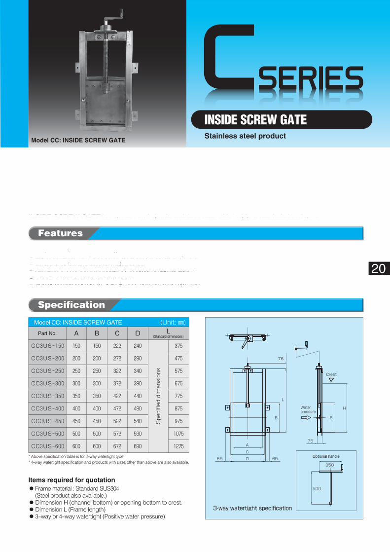
INSIDE SCREW GATEStainless steel product
Model CC: INSIDE SCREW GATE
Specification
Features
◦Simple structure and Low-cost gate.◦Light , compact with Inside screw type, easy to set up anywhere.◦Simple structure and easy for maintenance.◦Stainless steel product (SUS304). (Steel product also available.)◦Handle is detachable to prevent abuse.◦With using optional handle, Spindle does not come out from crest.
INSIDE SCREW GATE is compact and simple stainless gate with Inside screw hoisting device.
Model CC: INSIDE SCREW GATE� (Unit: ㎜)Part No. A B C D L
(Standard�dimensions)
CC3US-150 150 150 222 240
Spe
cifie
d dimen
sion
s
375
CC3US-200 200 200 272 290 475
CC3US-250 250 250 322 340 575
CC3US-300 300 300 372 390 675
CC3US-350 350 350 422 440 775
CC3US-400 400 400 472 490 875
CC3US-450 450 450 522 540 975
CC3US-500 500 500 572 590 1075
CC3US-600 600 600 672 690 1275
* Above specification table is for 3-way watertight type.* 4-way watertight specification and products with sizes other than above are also available.
Items required for quotation◦��Frame material : Standard SUS304
(Steel product also available.)◦Dimension H (channel bottom) or opening bottom to crest.◦Dimension L (Frame length)◦3-way or 4-way watertight (Positive water pressure)
CSERIES
21
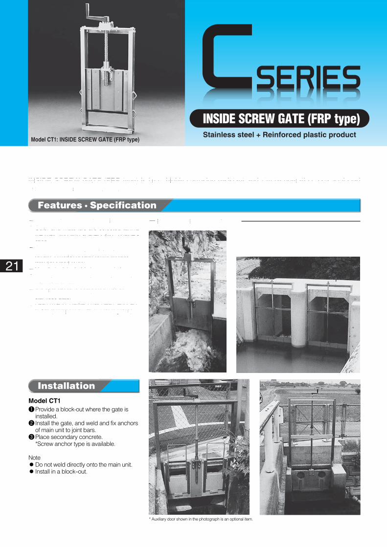
INSIDE SCREW GATE (FRP type)Stainless steel + Reinforced plastic product
Model CT1: INSIDE SCREW GATE (FRP type)
Features · Specification
◦��Light and highly corrosion resistant.◦��Color and materials are selected taking
the matching with scenery into consider-ation.
◦��Gate is made mainly of stainless steel. Shutter is made of plastics reinforced with long fiber glass.
◦��Handle is detachable to prevent abuse.◦��Spindle does not come out because of
the inside screw.◦��It is cost effective compared with all-
stainless gate.◦��Lead time for delivery has been reduced
to 1/2. (Compared with our steel gates)
INSIDE SCREW GATE (FRP type) is light, highly corrosion resistant and simple operation gate equipped with a handle-operated hoisting device.
■ Example of construction
Model CT1❶�Provide a block-out where the gate is
installed.❷�Install the gate, and weld and fix anchors
of main unit to joint bars.❸�Place secondary concrete.
*Screw anchor type is available.
Note◦��Do not weld directly onto the main unit.◦��Install in a block-out.
* Auxiliary door shown in the photograph is an optional item.
Installation
Extension handle Cover
GL GL
Secondary concrete
Water pressure
I
J
H
J
I
DE
B(Effective height)
A(Effective width)
Water pressure
Side anchor
Under-anchor
Inside screw type hoisting device
D(Frame width)
E
I
J
B(Effective height)
H(Frame height)
A(Effective width)
N(Shutter height)
Water pressure
Inside screw type hoisting device
Side anchor
Under-anchor
22
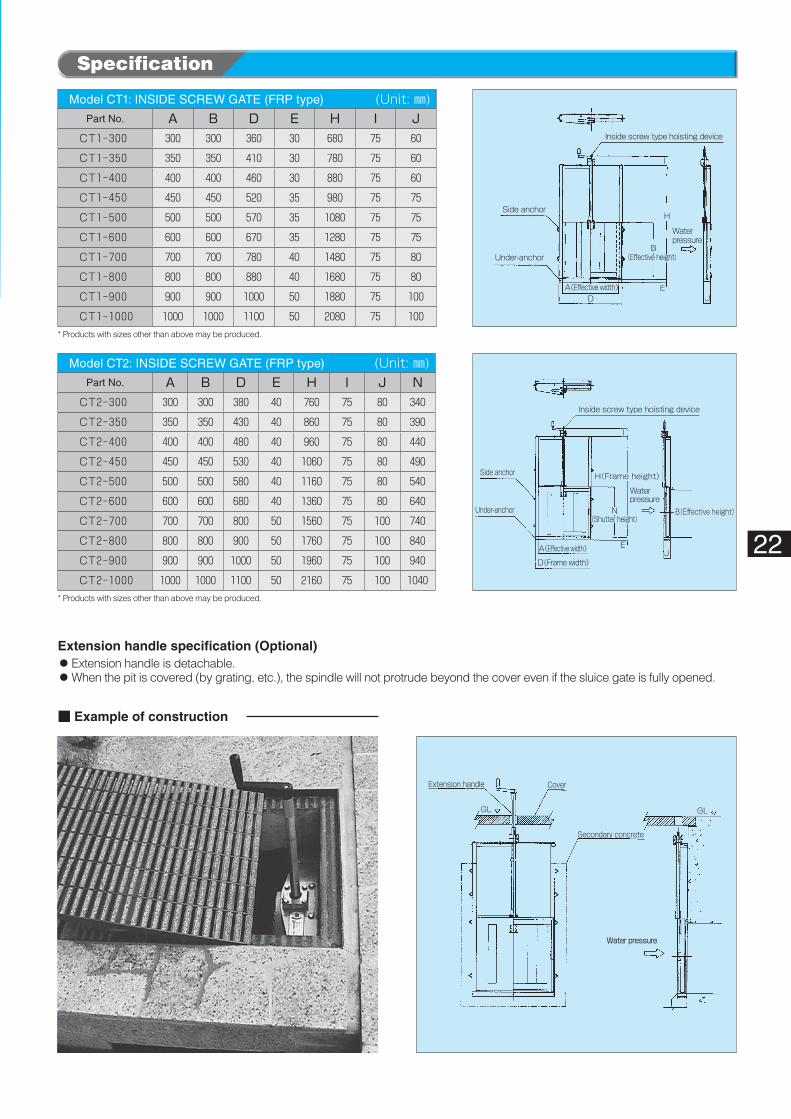
Specification
Model CT1: INSIDE SCREW GATE (FRP type)� (Unit: ㎜)Part No. A B D E H I J
CT1-300 300 300 360 30 680 75 60
CT1-350 350 350 410 30 780 75 60
CT1-400 400 400 460 30 880 75 60
CT1-450 450 450 520 35 980 75 75
CT1-500 500 500 570 35 1080 75 75
CT1-600 600 600 670 35 1280 75 75
CT1-700 700 700 780 40 1480 75 80
CT1-800 800 800 880 40 1680 75 80
CT1-900 900 900 1000 50 1880 75 100
CT1-1000 1000 1000 1100 50 2080 75 100
Model CT2: INSIDE SCREW GATE (FRP type)� (Unit: ㎜)Part No. A B D E H I J N
CT2-300 300 300 380 40 760 75 80 340
CT2-350 350 350 430 40 860 75 80 390
CT2-400 400 400 480 40 960 75 80 440
CT2-450 450 450 530 40 1060 75 80 490
CT2-500 500 500 580 40 1160 75 80 540
CT2-600 600 600 680 40 1360 75 80 640
CT2-700 700 700 800 50 1560 75 100 740
CT2-800 800 800 900 50 1760 75 100 840
CT2-900 900 900 1000 50 1960 75 100 940
CT2-1000 1000 1000 1100 50 2160 75 100 1040
■ Example of construction
Extension handle specification (Optional)◦��Extension handle is detachable.◦��When the pit is covered (by grating, etc.), the spindle will not protrude beyond the cover even if the sluice gate is fully opened.
* Products with sizes other than above may be produced.
* Products with sizes other than above may be produced.
CSERIES
4-way watertight specification
Optional handleA(Effective width)
Waterpressure
C
D
L
B
82
56
350
500
125
Crest
(Effective height)
23
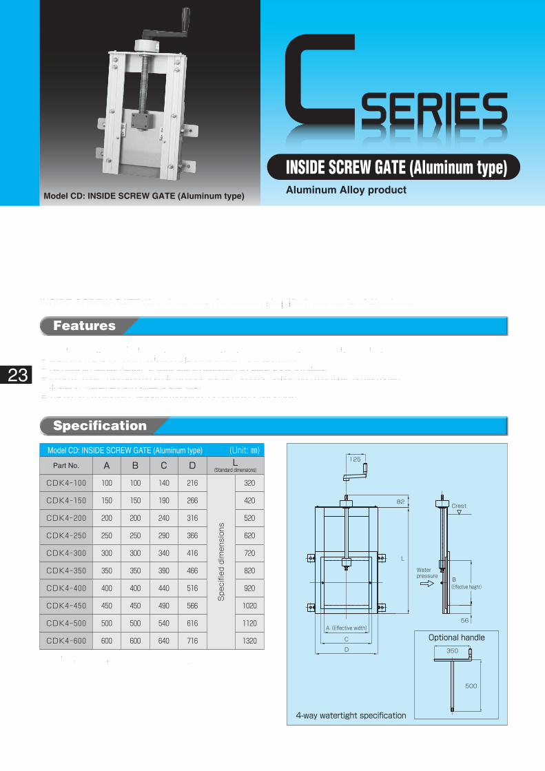
INSIDE SCREW GATE (Aluminum type)Aluminum Alloy product
Model CD: INSIDE SCREW GATE (Aluminum type)
Specification
Features
◦ Inside screw gate is made mainly Aluminum Alloy, superior in matching with scenery and compact.◦Light and highly corrosion resistant , Light and smooth hoist operation.◦No need to replace rubber for deterioration because no rubber parts are used.◦��It can be easy to set up in concrete BOX for storage, Because spindle does not move up and down.
(Install for pavement and street is effective)◦Taking on rail structure , Height of mounting anchor plate is adjustable.
INSIDE SCREW GATE (Aluminum type) is compact simplified gate made of Aluminum.
* Recommended water depth is less than 2.0 m.* Products with sizes other than above and 3-way watertight specification are also available.
Model CD: INSIDE SCREW GATE (Aluminum type)� (Unit: ㎜)Part No. A B C D L
(Standard�dimensions)
CDK4-100 100 100 140 216
Spe
cifie
d dimen
sion
s
320
CDK4-150 150 150 190 266 420
CDK4-200 200 200 240 316 520
CDK4-250 250 250 290 366 620
CDK4-300 300 300 340 416 720
CDK4-350 350 350 390 466 820
CDK4-400 400 400 440 516 920
CDK4-450 450 450 490 566 1020
CDK4-500 500 500 540 616 1120
CDK4-600 600 600 640 716 1320
CSERIES
Light-weight shutter
Shutter width:B
Bore diameter:φA
Waterpressure
Screw anchor
Inside screw type hoisting device Detachable handle
Frame width:C
Shutter height:E
F
GL
350
50076
F
500GL
350
76
Shutter height:E
Effective height:A2
Inside screw type hoisting device Detachable handle
Screw anchor Light-weight shutter
Effective width:A1
Frame width:C
Waterpressure
Bore height:A2
24
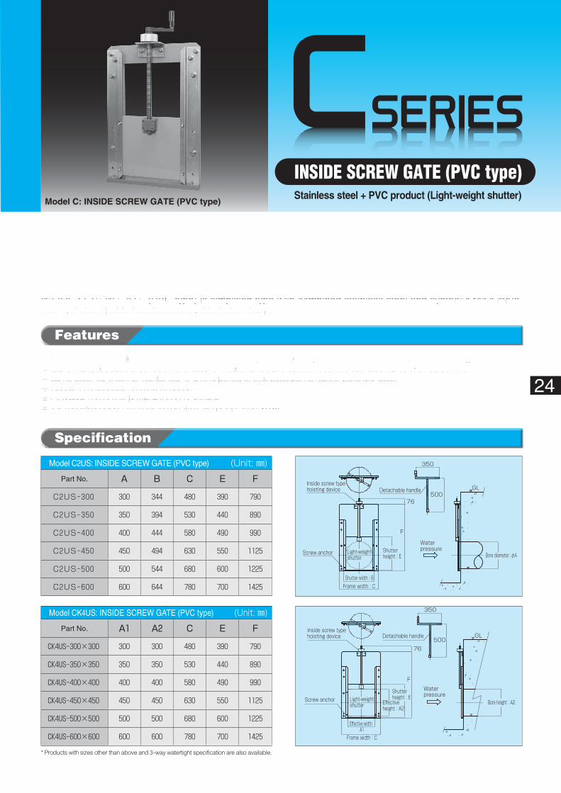
INSIDE SCREW GATE (PVC type)Stainless steel + PVC product (Light-weight shutter)
Model C: INSIDE SCREW GATE (PVC type)
* Products with sizes other than above and 3-way watertight specification are also available.
Specification
Features
◦Frame is made of stainless steel while shutter and doorstop are made of synthetic resin, in order to maximize advantage of materials.◦Light, highly resistant to corrosion and easy for maintenance and control. It can be operated lightly even by seniors.◦Same water tightness is maintained for a long period of time because no rubber parts are used.◦Handle is detachable to prevent abuse.◦Cross-section of flow is made round or square.◦ It is recommended to use for the depth of water less than 2.0 m.
INSIDE SCREW GATE (PVC type) is simplified type with combined stainless steel and synthetic resin struc-ture and detachable handle-operated hoisting device.
Model C2US: INSIDE SCREW GATE (PVC type)� (Unit: ㎜)Part No. A B C E F
C2US-300 300 344 480 390 790
C2US-350 350 394 530 440 890
C2US-400 400 444 580 490 990
C2US-450 450 494 630 550 1125
C2US-500 500 544 680 600 1225
C2US-600 600 644 780 700 1425
Model CK4US: INSIDE SCREW GATE (PVC type)� (Unit: ㎜)Part No. A1 A2 C E F
CK4US-300×300 300 300 480 390 790
CK4US-350×350 350 350 530 440 890
CK4US-400×400 400 400 580 490 990
CK4US-450×450 450 450 630 550 1125
CK4US-500×500 500 500 680 600 1225
CK4US-600×600 600 600 780 700 1425
DSERIES
A(70)
M10
B
φD
φC
Water pressure
Delivery outlet
Handle
Thread
Rubber packing
Deliveryoutlet
25
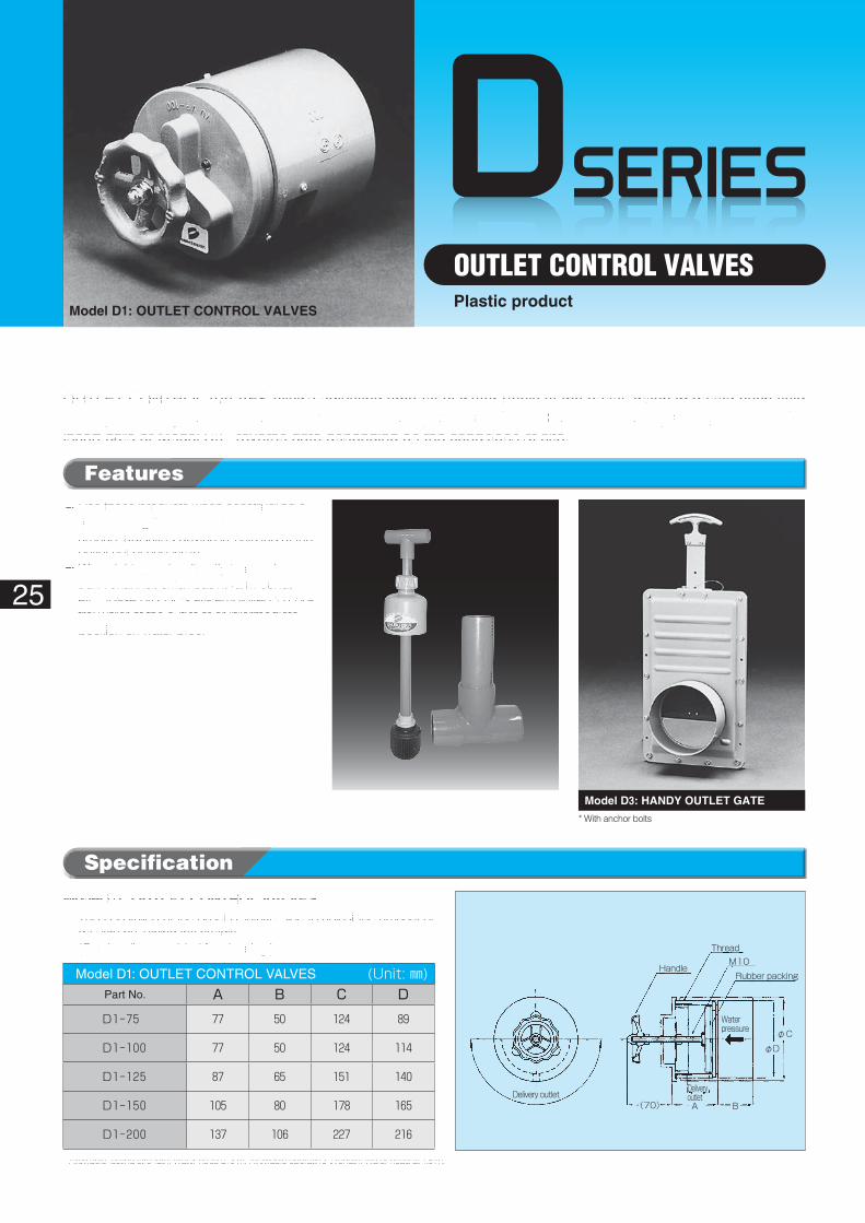
OUTLET CONTROL VALVESPlastic product
Model D1: OUTLET CONTROL VALVES
Model D1: OUTLET CONTROL VALVES� (Unit: ㎜)Part No. A B C D
D1-75 77 50 124 89
D1-100 77 50 124 114
D1-125 87 65 151 140
D1-150 105 80 178 165
D1-200 137 106 227 216
* With anchor bolts
Specification
Features
OUTLET CONTROL VALVES allows adjusting amount of water freely at the outlet, when irrigating each field directly from irrigation channel. (For reverse water pressure) Select Model D1 · rotary valve, Model D2C · insert gate or Model D3 · reverse gate depending on the conditions at site.
◦��Use these products when constructing a road utilizing the channel bed or a water amount adjusting device is installed at the outlet out of necessity.
◦��When taking water directly from a deep trunk channel, small basin, farm pond, etc., these products are employed to con-trol water at the outlet of or intermediate position on water pipe.
* Allowable testing strength: Water head at 3 m. Allowable operating strength: Water head at 1.5 m.
Model D1: OUTLET CONTROL VALVES◦��This is installed at the outlet of intake pipe to adjust the amount of
delivery by turning the handle. (Can be disassembled for cleaning.)
Model D2C: HANDY SLUICE PLUG Model D3: HANDY OUTLET GATE
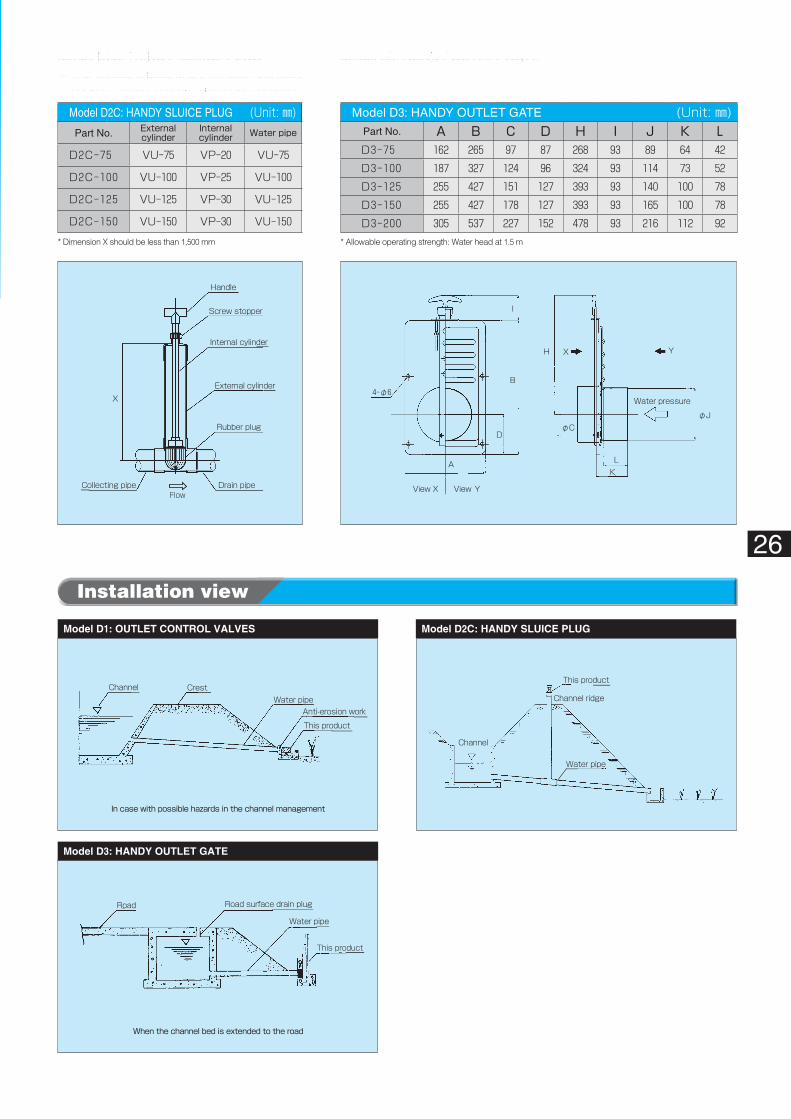
When the channel bed is extended to the road
Road
Water pipe
Road surface drain plug
This product
In case with possible hazards in the channel management
Channel CrestWater pipe
Anti-erosion work
This product
Handle
Screw stopper
Internal cylinder
External cylinder
Rubber plug
Drain pipeCollecting pipe
X
Flow
Water pressure
View X View Y
X Y
LK
H
I
B
D
A
4-φ6
φJφC
Channel
Channel ridge
Water pipe
This product
26
Installation view
Model D2C: HANDY SLUICE PLUG◦��This product is used where the open and close
control is provided at an intermediate position.
Model D3: HANDY OUTLET GATE
Model D3: HANDY OUTLET GATE� (Unit: ㎜)Part No. A B C D H I J K LD3-75 162 265 97 87 268 93 89 64 42
D3-100 187 327 124 96 324 93 114 73 52
D3-125 255 427 151 127 393 93 140 100 78
D3-150 255 427 178 127 393 93 165 100 78
D3-200 305 537 227 152 478 93 216 112 92
Model D2C: HANDY SLUICE PLUG� (Unit: ㎜)Part No. External
cylinderInternalcylinder Water�pipe
D2C-75 VU-75 VP-20 VU-75
D2C-100 VU-100 VP-25 VU-100
D2C-125 VU-125 VP-30 VU-125
D2C-150 VU-150 VP-30 VU-150
* Dimension X should be less than 1,500 mm * Allowable operating strength: Water head at 1.5 m
Model D3: HANDY OUTLET GATE
Model D1: OUTLET CONTROL VALVES Model D2C: HANDY SLUICE PLUG
ESERIES
Drainage channel
Channel ridge Top of Internal cylinderSoil retaining work (Bags with soil)
Paddy field surface
Water level of paddy field
Open-cut after drainage
Winter time drain holeDrain pipe
27
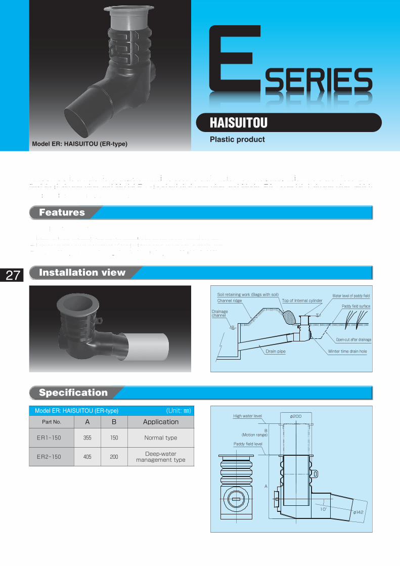
HAISUITOUPlastic product
Model ER: HAISUITOU (ER-type)
Model ER: HAISUITOU (ER-type)� (Unit: ㎜)Part No. A B Application
ER1-150 355 150 Normal type
ER2-150 405 200 Deep-watermanagement type
Specification
Features
Model ER: HAISUITOU (ER-type)◦��Depth of water in paddy field can be adjusted by elevating the internal cylinder.◦��Draining water run off from winter draining hole of external cylinder at winter time.◦��In case of the position for draining at winter time is deep , use Model EA · ER2.
HAISUITOU is a water level adjuster which is used to drain water from the paddy field. There are Model ER · flexible drainage pipe and Model E · standard drainage pipe and Model EA · special drainage pipe, which are selected depending on the conditions at site.
Installation view
φ200High water level
Paddy field level
B
A
10°φ142
(Motion range)
φBInternal cylinder
External cylinder
Closing cap(Winter time draining) Drain pipe
D
X
G
φA
28
❶�Standard sizes for drainage pipe per unit block area are considered to be 100 for 1,000 square meters, 125 per 2,000 square meters and 150 per 3,000 square meters, though it could vary depending on the amount of rainfall, draining time, depth of impound water, or other, at particular area. It is considered also to install the product at two or more places in unit block area.
❷�Since the L shape external cylinder is installed at approx. 100°and an O ring is attached to the joint to drain pipe, it can be installed arbitrarily under ordinary conditions. Where it is installed at a very steep slope, use the drain pipe after cutting obliquely. (Model E)
❸�Install the drainage pipe with its top end at approx. 30 mm below the average height of the surface of paddy field.
❹�When burying the drainage pipe, tread down the ground sufficiently after it is buried.
❺�Since this drainage pipe is buried at the end toe of slope in principle, use a semi circular concrete pipe, short U shape flume, building block, sand bag, etc., as logging for the slope.
❻�When installing the internal cylinder, set it with the triangle mark indicated on the flange oriented to the surface of paddy field. Lock further the internal cylinder with the at-tached O ring. (Model E)
❼�Since the drain hole for winter time is utilized as a draining hole after draining rice farming water or during secondary crop farming, it is opened if it is inserted with the triangle mark oriented to the drainage channel. Cut open the front of the opening to secure a complete draining. (Model E)
Installation
* X (Standard dimension: 400 mm)
FeaturesModel E: HAISUITOU (E-type)◦��Depth of water in paddy field can be adjusted
by elevating the internal cylinder. (Up to 120 mm)◦��After draining water or for draining at winter
time (or secondary crop period), rain water can be drained through the winter draining hole on the external cylinder to dry the paddy field.
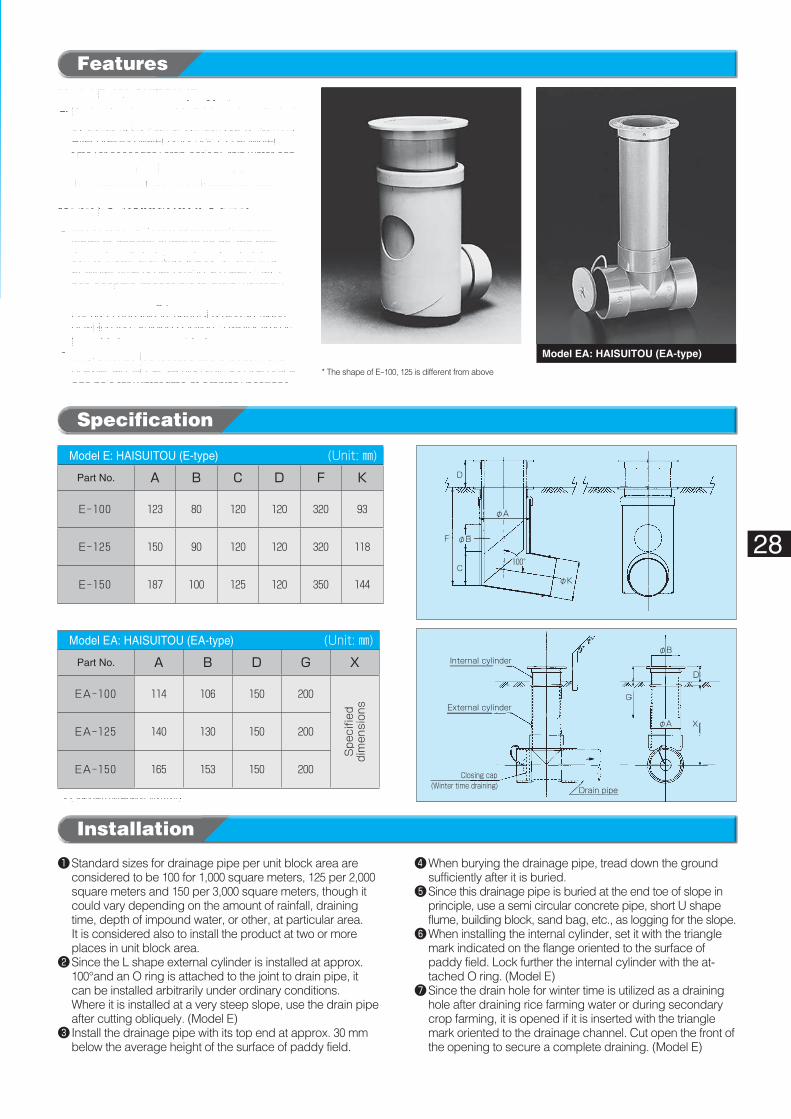
Model EA: HAISUITOU (EA-type)◦��Along with the promotion of agricultural
lands to general purpose fields, the posi-tion to install drainage pipes for draining at winter time is becoming so deep that it has become impossible to drain water by standard draining pipes. For such occasions, special drainage pipes of which the draining position in winter time is brought down are provided.
◦��Vinyl chloride tee located at the bottom end of external cylinder allows providing the drain-age hole for winter time at arbitrary positions.
Model E: HAISUITOU (E-type) Model EA: HAISUITOU (EA-type)
Specification
Model E: HAISUITOU (E-type)� (Unit: ㎜)Part No. A B C D F K
E-100 123 80 120 120 320 93
E-125 150 90 120 120 320 118
E-150 187 100 125 120 350 144
Model EA: HAISUITOU (EA-type)� (Unit: ㎜)Part No. A B D G X
EA-100 114 106 150 200
Spe
cifie
ddimen
sion
s
EA-125 140 130 150 200
EA-150 165 153 150 200
φA
φB
φK
D
F
C100°
* The shape of E-100, 125 is different from above
ESERIES
A
B F
E
D
G
H
φC
29
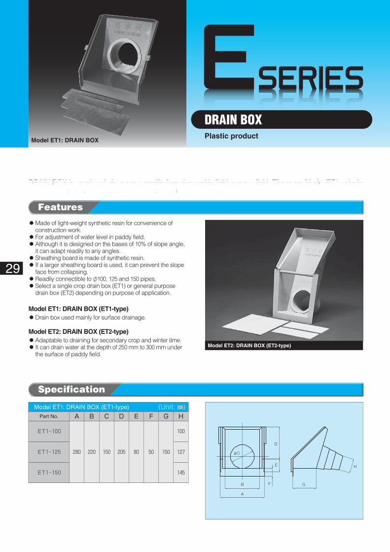
DRAIN BOXPlastic product
Model ET1: DRAIN BOX
Model ET2: DRAIN BOX (ET2-type)
Specification
Features
DRAIN BOX is used to drain water speedily from the paddy field at each field. There are Model ET1 · single crop DRAIN BOX and Model ET2 · general purpose DRAIN BOX.
Model ET1: DRAIN BOX (ET1-type)� (Unit: ㎜)Part No. A B C D E F G H
ET1-100
280 220 150 205 80 50 150
100
ET1-125 127
ET1-150 145
◦��Made of light-weight synthetic resin for convenience of construction work.
◦��For adjustment of water level in paddy field.◦��Although it is designed on the bases of 10% of slope angle,
it can adapt readily to any angles.◦��Sheathing board is made of synthetic resin.◦��If a larger sheathing board is used, it can prevent the slope
face from collapsing.◦��Readily connectible to φ100, 125 and 150 pipes.◦��Select a single crop drain box (ET1) or general purpose
drain box (ET2) depending on purpose of application.
Model ET1: DRAIN BOX (ET1-type)◦��Drain box used mainly for surface drainage.
Model ET2: DRAIN BOX (ET2-type)◦��Adaptable to draining for secondary crop and winter time.◦��It can drain water at the depth of 250 mm to 300 mm under
the surface of paddy field.
φD
AB
EF
G
H
I
L
M
J
C
K
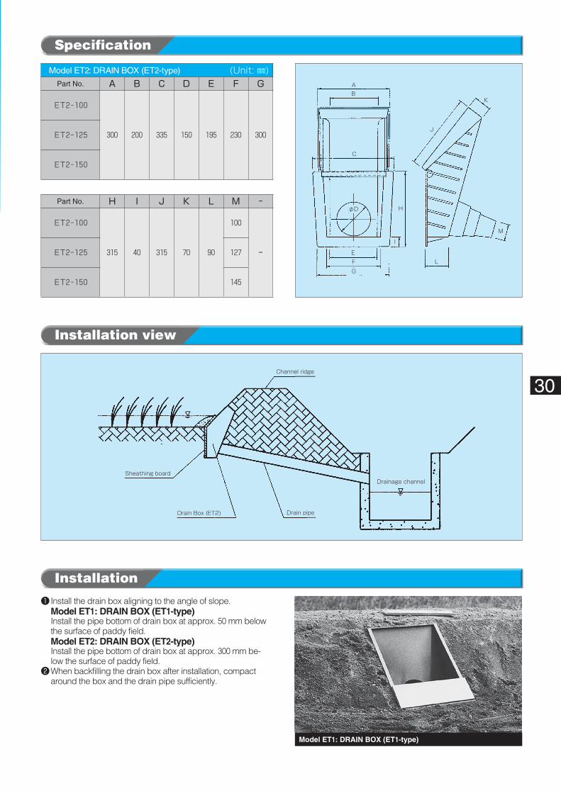
Channel ridge
Drainage channel
Drain pipeDrain Box (ET2)
Sheathing board
30
Model ET1: DRAIN BOX (ET1-type)
❶�Install the drain box aligning to the angle of slope.Model ET1: DRAIN BOX (ET1-type)Install the pipe bottom of drain box at approx. 50 mm below the surface of paddy field. Model ET2: DRAIN BOX (ET2-type)Install the pipe bottom of drain box at approx. 300 mm be-low the surface of paddy field.
❷�When backfilling the drain box after installation, compact around the box and the drain pipe sufficiently.
Installation
Installation view
Specification
Model ET2: DRAIN BOX (ET2-type)� (Unit: ㎜)Part No. A B C D E F G
ET2-100
300 200 335 150 195 230 300ET2-125
ET2-150
Part No. H I J K L M ‐
ET2-100
315 40 315 70 90
100
‐ET2-125 127
ET2-150 145
FSERIES
31
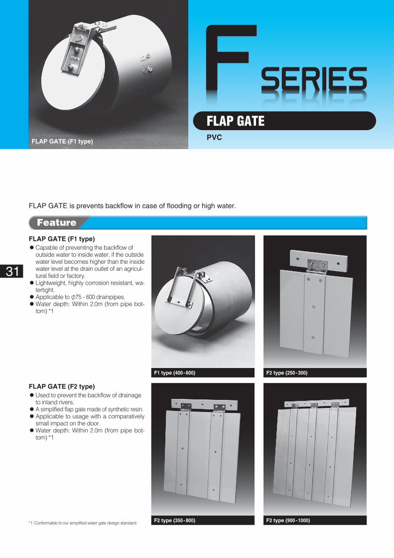
FLAP GATEPVC
FLAP GATE (F1 type)◦��Capable of preventing the backflow of
outside water to inside water, if the outside water level becomes higher than the inside water level at the drain outlet of an agricul-tural field or factory.
◦��Lightweight, highly corrosion resistant, wa-tertight.
◦Applicable to φ75 - 600 drainpipes.◦��Water depth: Within 2.0m (from pipe bot-
tom) *1
FLAP GATE (F2 type)◦��Used to prevent the backflow of drainage
to inland rivers.◦��A simplified flap gate made of synthetic resin.◦��Applicable to usage with a comparatively
small impact on the door.◦��Water depth: Within 2.0m (from pipe bot-
tom) *1
FLAP GATE is prevents backflow in case of flooding or high water.
*1 : Conformable to our simplified water gate design standard.
FLAP GATE (F1 type)
F2 type (900 -1000)
F1 type (400 -600) F2 type (250 -300)
F2 type (350 -800)
Feature
φC
A
φB
2-M6Anchor
E
φA
t
E
A
B t
M10 Anchor
E
A
B t
M10 Anchor
E
A
B t
M10 Anchor
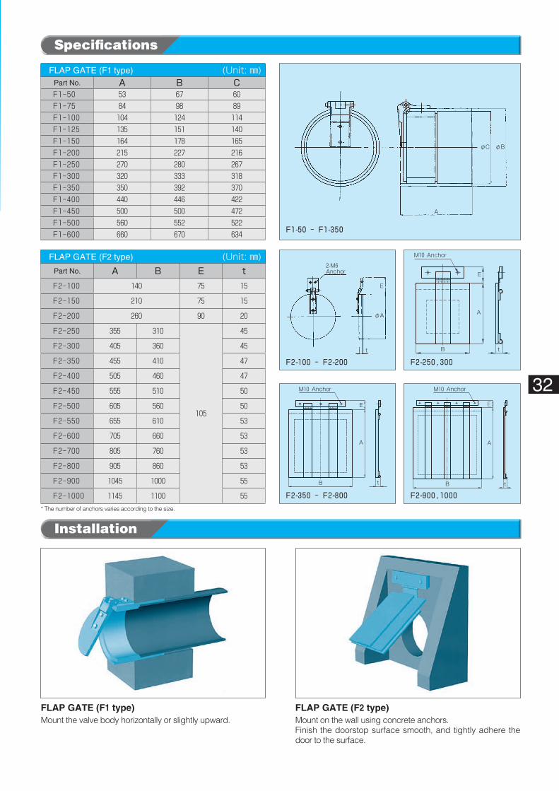
F1-50 ‐ F1-350
F2-100 ‐ F2-200 F2-250,300
F2-350 ‐ F2-800 F2-900,1000
32
* The number of anchors varies according to the size.
FLAP GATE (F1 type)Mount the valve body horizontally or slightly upward.
FLAP GATE (F2 type)Mount on the wall using concrete anchors.Finish the doorstop surface smooth, and tightly adhere the door to the surface.
FLAP GATE (F1 type) (Unit: ㎜)Part No. A B CF1-50 53 67 60F1-75 84 98 89F1-100 104 124 114F1-125 135 151 140F1-150 164 178 165F1-200 215 227 216F1-250 270 280 267F1-300 320 333 318F1-350 350 392 370F1-400 440 446 422F1-450 500 500 472F1-500 560 552 522F1-600 660 670 634
FLAP GATE (F2 type) (Unit: ㎜)Part No. A B E tF2-100 140 75 15
F2-150 210 75 15
F2-200 260 90 20
F2-250 355 310
105
45
F2-300 405 360 45
F2-350 455 410 47
F2-400 505 460 47
F2-450 555 510 50
F2-500 605 560 50
F2-550 655 610 53
F2-600 705 660 53
F2-700 805 760 53
F2-800 905 860 53
F2-900 1045 1000 55
F2-1000 1145 1100 55
Specifications
Installation
FSERIES
A A A
B B B
Hinge Hinge Hinge
400~600
C C C
300~350 700~1000
t
Unequal-sided pipe Unequal-sided pipe Unequal-sided pipe
33
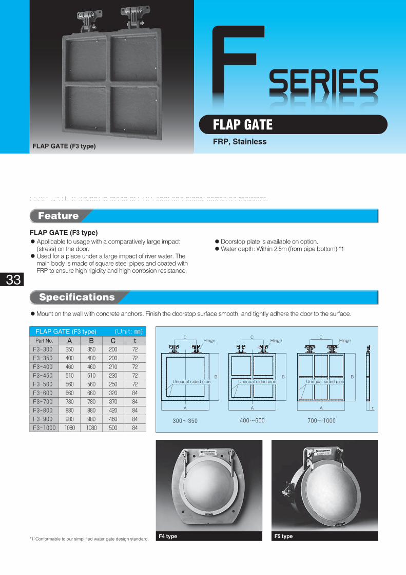
FLAP GATEFRP, Stainless
FLAP GATE (F3 type)
FLAP GATE (F3 type)◦ Applicable to usage with a comparatively large impact
(stress) on the door.◦ Used for a place under a large impact of river water. The
main body is made of square steel pipes and coated with FRP to ensure high rigidity and high corrosion resistance.
◦Doorstop plate is available on option.◦Water depth: Within 2.5m (from pipe bottom) *1
◦ Mount on the wall with concrete anchors. Finish the doorstop surface smooth, and tightly adhere the door to the surface.
*1 : Conformable to our simplified water gate design standard.
FLAP GATE (F3 type)� (Unit: ㎜)Part No. A B C tF3-300 350 350 200 72F3-350 400 400 200 72F3-400 460 460 210 72F3-450 510 510 230 72F3-500 560 560 250 72F3-600 660 660 320 84F3-700 780 780 370 84F3-800 880 880 420 84F3-900 980 980 460 84F3-1000 1080 1080 500 84
F4 type F5 type
Feature
Specifications
FLAP GATE (F3 type) is made of FRP, light and highly corrosion resistant.
M12×100(Anchor)
Hm
C
B
φA
J K
OpeningφA
Hm
HPφA
C
B
OpeningφA
J K
34
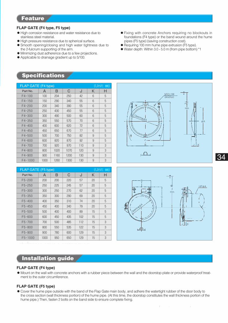
FLAP GATE (F4 type, F5 type)◦ High corrosion resistance and water resistance due to
stainless steel material.◦High pressure resistance due to spherical surface.◦ Smooth opening/closing and high water tightness due to
the 2-fulcrum supporting of the arm.◦Minimizing dust adherence due to a few projections.◦Applicable to drainage gradient up to 5/100.
◦ Fixing with concrete Anchors requiring no blockouts in foundations (F4 type) or the band wound around the hume pipes (F5 type) (saving construction cost).
◦Requiring 100 mm hume pipe extrusion (F5 type).◦Water depth: Within 3.0 - 5.0 m (from pipe bottom) *1
FLAP GATE (F4 type)◦ Mount on the wall with concrete anchors with a rubber piece between the wall and the doorstop plate or provide waterproof treat-
ment to the outer circumference.
FLAP GATE (F5 type)◦ Cover the hume pipe outside with the band of the Flap Gate main body, and adhere the watertight rubber of the door body to
the cross section (wall thickness portion) of the hume pipe. (At this time, the doorstop constitutes the wall thickness portion of the hume pipe.) Then, fasten 2 bolts on the band side to ensure complete fixing.
FLAP GATE (F4 type)� (Unit: ㎜)Part No. A B C J K HF4-100 100 204 250 42 6 5F4-150 150 290 340 55 6 5F4-200 200 340 390 55 6 5F4-250 250 430 450 55 6 5F4-300 300 490 500 60 6 5F4-350 350 550 570 70 6 5F4-400 400 600 620 72 6 5F4-450 450 650 670 77 6 5F4-500 500 700 750 82 9 5F4-600 600 820 870 92 9 5F4-700 700 920 970 110 9 3F4-800 800 1020 1070 120 9 3F4-900 900 1160 1200 130 9 3F4-1000 1000 1260 1300 130 9 3
FLAP GATE (F5 type)� (Unit: ㎜)Part No. A B C J K HF5-200 200 200 220 57 20 5
F5-250 250 225 245 57 20 5
F5-300 300 250 270 62 20 5
F5-350 350 300 290 69 20 5
F5-400 400 350 310 74 20 5
F5-450 450 400 340 79 20 5
F5-500 500 400 400 89 15 5
F5-600 600 450 435 102 15 5
F5-700 700 500 485 112 15 3
F5-800 800 550 535 122 15 3
F5-900 900 780 600 129 15 3
F5-1000 1000 950 650 129 15 3
Installation guide
* For any sizes other than the above or non-fume pipes, consult with us.
*1 : Conformable to our simplified water gate design standard.
Feature
Specifications
FSERIES
I
G
F
A(Effective width)
C
E
H.W.L
2.5m
Wall surface
D
B(Effective height)
L M
35
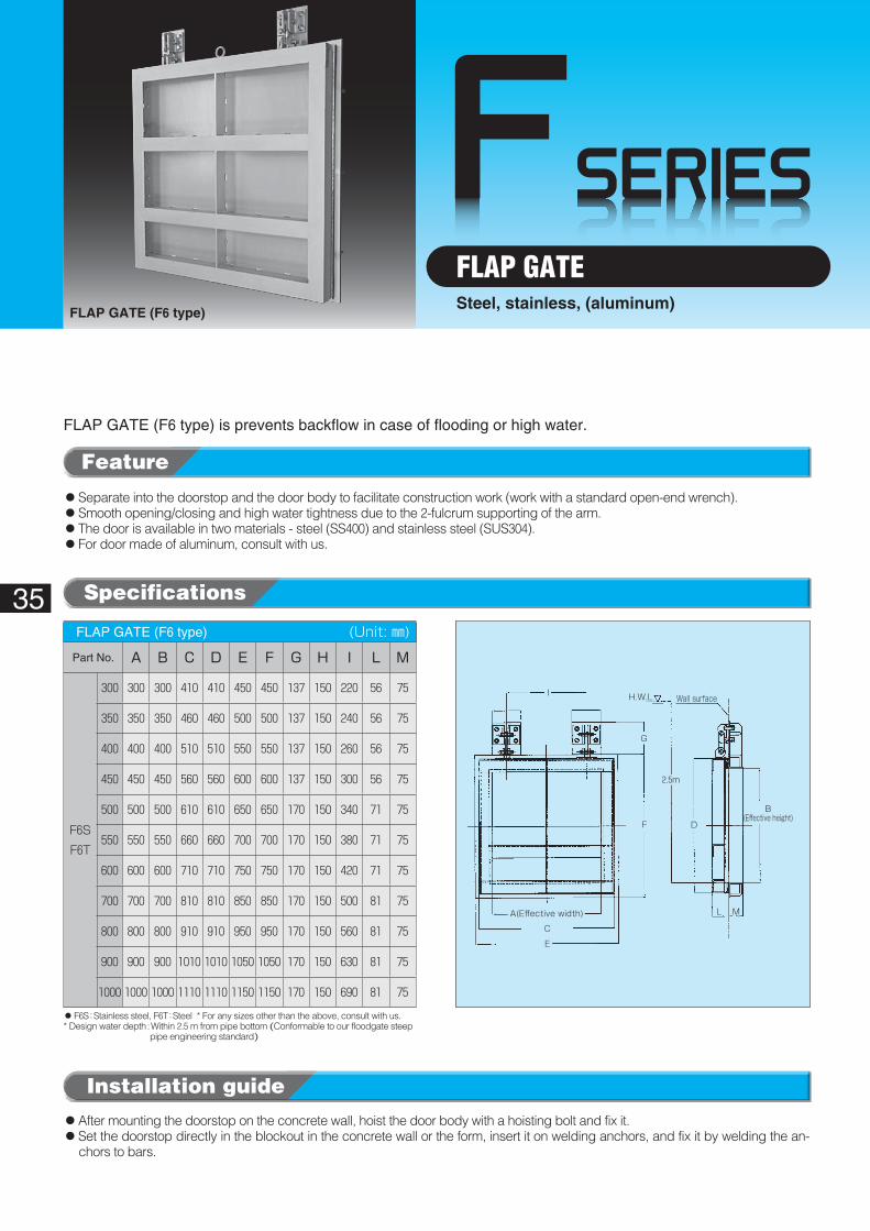
FLAP GATESteel, stainless, (aluminum)
FLAP GATE (F6 type)
◦Separate into the doorstop and the door body to facilitate construction work (work with a standard open-end wrench).◦Smooth opening/closing and high water tightness due to the 2-fulcrum supporting of the arm.◦The door is available in two materials - steel (SS400) and stainless steel (SUS304).◦For door made of aluminum, consult with us.
FLAP GATE (F6 type) is prevents backflow in case of flooding or high water.
◦After mounting the doorstop on the concrete wall, hoist the door body with a hoisting bolt and fix it.◦�Set the doorstop directly in the blockout in the concrete wall or the form, insert it on welding anchors, and fix it by welding the an-
chors to bars.
◦�F6S : Stainless steel, F6T : Steel * For any sizes other than the above, consult with us.* �Design water depth : Within 2.5 m from pipe bottom (Conformable to our floodgate steep
pipe engineering standard)
FLAP GATE (F6 type)� (Unit: ㎜)
Part No. A B C D E F G H I L M
F6S
F6T
300 300 300 410 410 450 450 137 150 220 56 75
350 350 350 460 460 500 500 137 150 240 56 75
400 400 400 510 510 550 550 137 150 260 56 75
450 450 450 560 560 600 600 137 150 300 56 75
500 500 500 610 610 650 650 170 150 340 71 75
550 550 550 660 660 700 700 170 150 380 71 75
600 600 600 710 710 750 750 170 150 420 71 75
700 700 700 810 810 850 850 170 150 500 81 75
800 800 800 910 910 950 950 170 150 560 81 75
900 900 900 1010 1010 1050 1050 170 150 630 81 75
1000 1000 1000 1110 1110 1150 1150 170 150 690 81 75
Installation guide
Feature
Specifications
FSERIES
H
D
F
J
100~450 500~600
D
G18
4-φ13 anchor holeM10 Anchor
Water depth: Within 2.5 m 6-φ13 anchor holeM10 Anchor
Opening dia.:φA
Door body.:φB
Opening dia.:φA
Door body.:φ
B
Opening dia.:φA
Doorstop width:C
Waterproof rubber
DJ
H
F G18
Water depth: Within 2.5 mP-φ13 anchor holeM10 Anchor
Doorstop width:C
Doorstop width:B
Opening width: A
Opening height: ADoor body height: B
Waterproof rubber
Opening height: A
36
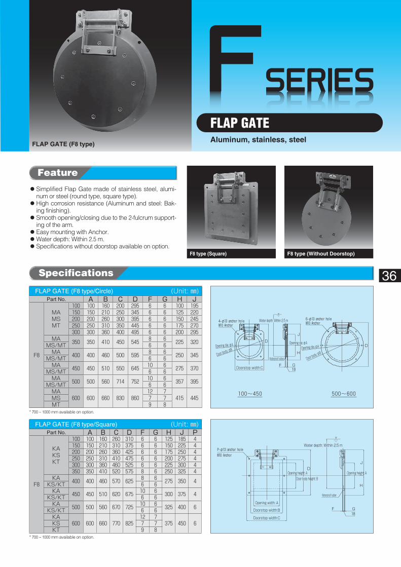
FLAP GATEAluminum, stainless, steel
FLAP GATE (F8 type)
F8 type (Square) F8 type (Without Doorstop)
◦ Simplified Flap Gate made of stainless steel, alumi-num or steel (round type, square type).
◦�High corrosion resistance (Aluminum and steel: Bak-ing finishing).
◦ Smooth opening/closing due to the 2-fulcrum support-ing of the arm.
◦Easy mounting with Anchor.◦Water depth: Within 2.5 m.◦Specifications without doorstop available on option.
FLAP GATE (F8 type/Circle)� (Unit: ㎜)Part No. A B C D F G H J
F8
MAMSMT
100 100 160 200 295 6 6 100 195150 150 210 250 345 6 6 125 220200 200 260 300 395 6 6 150 245250 250 310 350 445 6 6 175 270300 300 360 400 495 6 6 200 295
MA 350 350 410 450 545 8 6 225 320MS/MT 6 6MA 400 400 460 500 595 8 6 250 345MS/MT 6 6MA 450 450 510 550 645 10 6 275 370MS/MT 6 6MA 500 500 560 714 752 10 6 357 395MS/MT 6 6MA
600 600 660 830 86012 7
415 445MS 7 7MT 9 8
FLAP GATE (F8 type/Square)� (Unit: ㎜)Part No. A B C D F G H J P
F8
KAKSKT
100 100 160 260 310 6 6 125 185 4150 150 210 310 375 6 6 150 225 4200 200 260 360 425 6 6 175 250 4250 250 310 410 475 6 6 200 275 4300 300 360 460 525 6 6 225 300 4350 350 410 520 575 8 6 250 325 4
KA 400 400 460 570 625 8 6 275 350 4KS/KT 6 6KA 450 450 510 620 675 10 6 300 375 4KS/KT 6 6KA 500 500 560 670 725 10 6 325 400 6KS/KT 6 6KA
600 600 660 770 82512 7
375 450 6KS 7 7KT 9 8
* 700 - 1000 mm available on option.
* 700 - 1000 mm available on option.
Specifications
Feature
FSERIES
H
C
F
G
φA φJ
Water depth: Within 2.5 m
HP or the like
Door body.:φB
H.W.LC
F G
E
Water depth: Within 2.5 m
Opening dia.:φA
Door body.:φB
M10 All Anchor
37
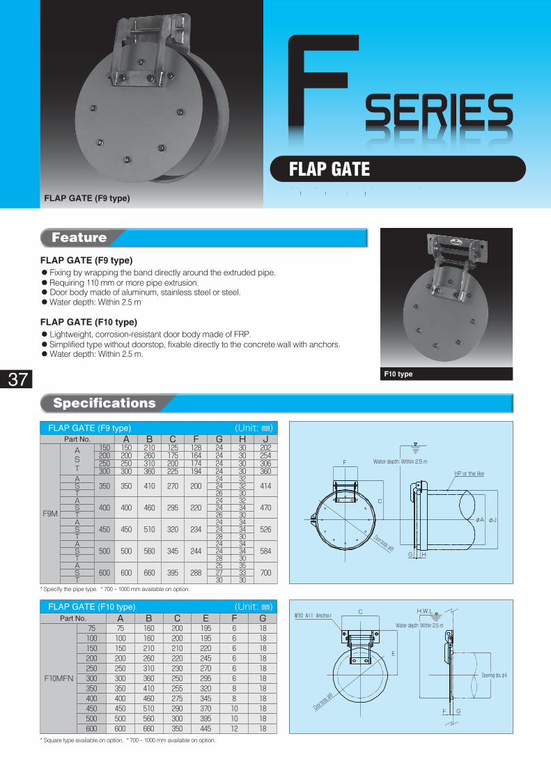
FLAP GATEFLAP GATE (F9 type)
F10 type
FLAP GATE (F9 type)� (Unit: ㎜)Part No. A B C F G H J
F9M
AST
150 150 210 125 128 24 30 202200 200 260 175 164 24 30 254250 250 310 200 174 24 30 306300 300 360 225 194 24 30 360
A350 350 410 270 200
24 32414S 24 32
T 26 30A
400 400 460 295 22024 32
470S 24 34T 26 30A
450 450 510 320 23424 34
526S 24 34T 28 30A
500 500 560 345 24424 34
584S 24 34T 28 30A
600 600 660 395 28825 35
700S 27 33T 30 30
FLAP GATE (F10 type)� (Unit: ㎜)Part No. A B C E F G
F10MFN
75 75 160 200 195 6 18100 100 160 200 195 6 18150 150 210 210 220 6 18200 200 260 220 245 6 18250 250 310 230 270 6 18300 300 360 250 295 6 18350 350 410 255 320 8 18400 400 460 275 345 8 18450 450 510 290 370 10 18500 500 560 300 395 10 18600 600 660 350 445 12 18
FLAP GATE (F9 type)◦Fixing by wrapping the band directly around the extruded pipe.◦Requiring 110 mm or more pipe extrusion.◦Door body made of aluminum, stainless steel or steel.◦Water depth: Within 2.5 m
FLAP GATE (F10 type)◦Lightweight, corrosion-resistant door body made of FRP.◦Simplified type without doorstop, fixable directly to the concrete wall with anchors.◦Water depth: Within 2.5 m.
* Specify the pipe type. * 700 - 1000 mm available on option.
* Square type available on option. * 700 - 1000 mm available on option.
Specifications
Feature
Aluminum, stainless, steel
FSERIES
A
φC
φB
Existing PVC pipe
38
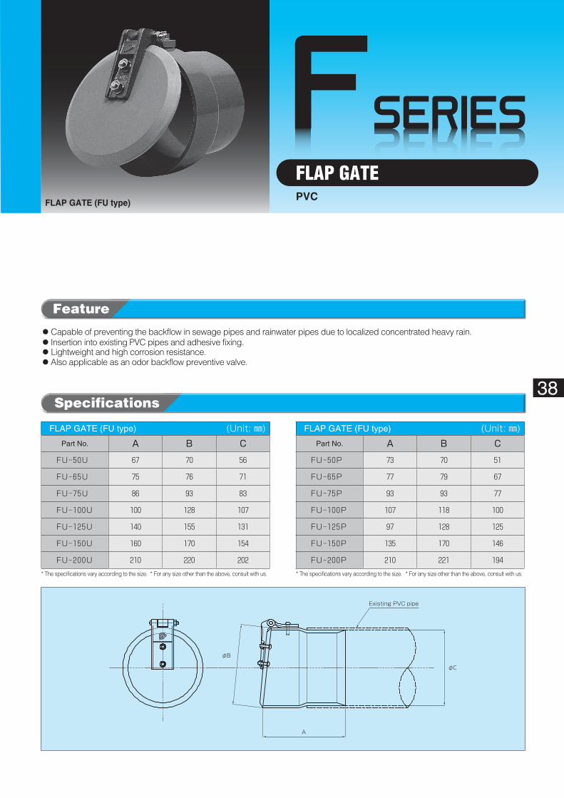
FLAP GATEPVC
FLAP GATE (FU type)
FLAP GATE (FU type)� (Unit: ㎜)Part No. A B C
FU-50U 67 70 56
FU-65U 75 76 71
FU-75U 86 93 83
FU-100U 100 128 107
FU-125U 140 155 131
FU-150U 160 170 154
FU-200U 210 220 202
FLAP GATE (FU type)� (Unit: ㎜)Part No. A B C
FU-50P 73 70 51
FU-65P 77 79 67
FU-75P 93 93 77
FU-100P 107 118 100
FU-125P 97 128 125
FU-150P 135 170 146
FU-200P 210 221 194
◦Capable of preventing the backflow in sewage pipes and rainwater pipes due to localized concentrated heavy rain.◦ Insertion into existing PVC pipes and adhesive fixing.◦Lightweight and high corrosion resistance.◦Also applicable as an odor backflow preventive valve.
* The specifications vary according to the size. * For any size other than the above, consult with us. * The specifications vary according to the size.��* For any size other than the above, consult with us.
Specifications
Feature
39
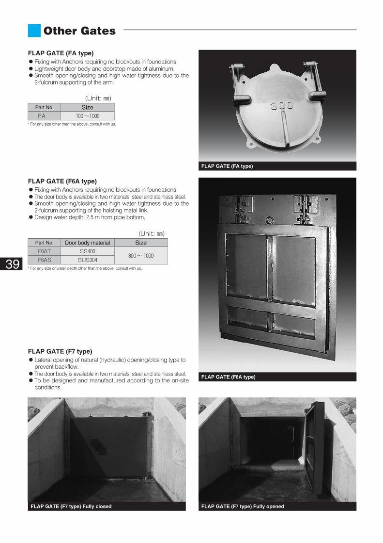
FLAP GATE (FA type)
FLAP GATE (F6A type)
FLAP GATE (F7 type) Fully openedFLAP GATE (F7 type) Fully closed
(Unit: ㎜)Part No. SizeFA 100 ~1000
(Unit: ㎜)Part No. Door body material SizeF6AT SS400
300 ~ 1000F6AS SUS304
FLAP GATE (FA type)◦Fixing with Anchors requiring no blockouts in foundations.◦Lightweight door body and doorstop made of aluminum.◦ Smooth opening/closing and high water tightness due to the
2-fulcrum supporting of the arm.
FLAP GATE (F7 type)◦ Lateral opening of natural (hydraulic) opening/closing type to
prevent backflow.◦The door body is available in two materials: steel and stainless steel.◦ To be designed and manufactured according to the on-site
conditions.
* For any size other than the above, consult with us.
* For any size or water depth other than the above, consult with us.
Other Gates
FLAP GATE (F6A type)◦Fixing with Anchors requiring no blockouts in foundations.◦The door body is available in two materials: steel and stainless steel.◦ Smooth opening/closing and high water tightness due to the
2-fulcrum supporting of the hoisting metal link.◦Design water depth: 2.5 m from pipe bottom.
40
GSERIES
For G-125 ‒ G-150 screw
Valve seat
Rubber valve
Socket
φB
E
L(Wall thickness)
φBφB
φCφD
E
◦Main�body
◦Valve
41
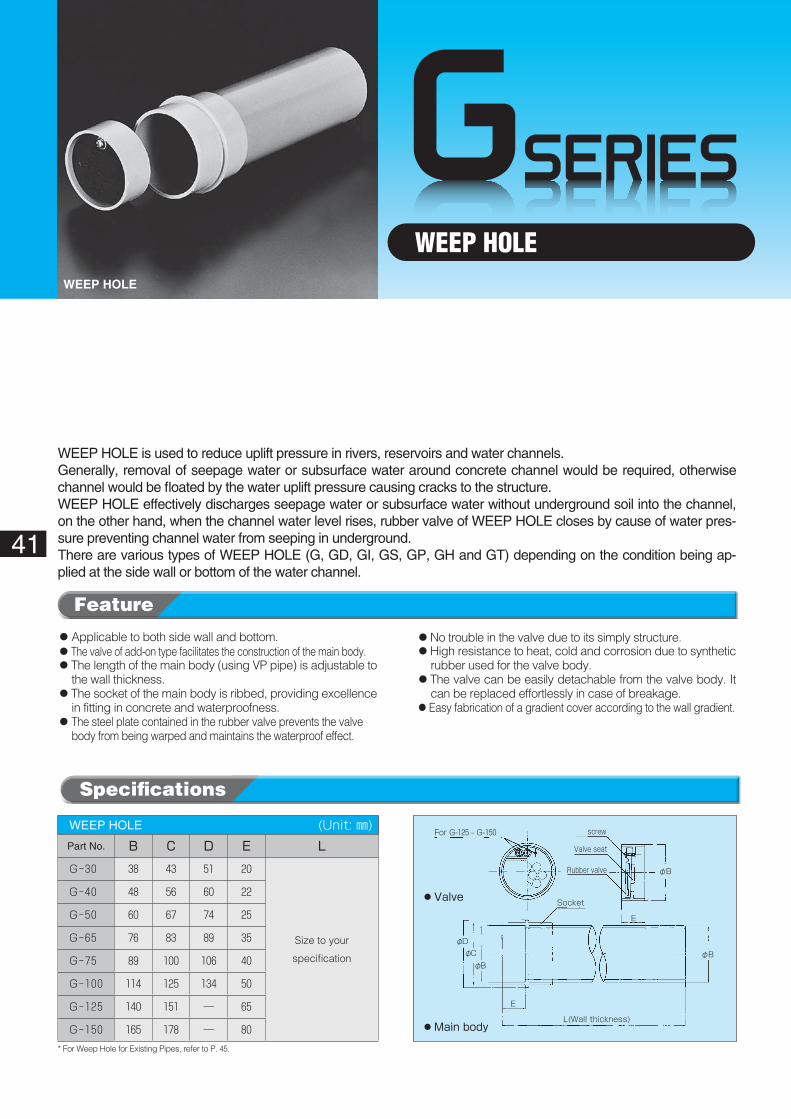
WEEP HOLEWEEP HOLE
WEEP HOLE� (Unit: ㎜)Part No. B C D E L
G-30 38 43 51 20
Size to your
specification
G-40 48 56 60 22
G-50 60 67 74 25
G-65 76 83 89 35
G-75 89 100 106 40
G-100 114 125 134 50
G-125 140 151 ― 65
G-150 165 178 ― 80
◦Applicable to both side wall and bottom.◦The valve of add-on type facilitates the construction of the main body.◦ The length of the main body (using VP pipe) is adjustable to
the wall thickness.◦ The socket of the main body is ribbed, providing excellence
in fitting in concrete and waterproofness.◦ The steel plate contained in the rubber valve prevents the valve
body from being warped and maintains the waterproof effect.
◦No trouble in the valve due to its simply structure.◦ High resistance to heat, cold and corrosion due to synthetic
rubber used for the valve body.◦ The valve can be easily detachable from the valve body. It
can be replaced effortlessly in case of breakage.◦Easy fabrication of a gradient cover according to the wall gradient.
* For Weep Hole for Existing Pipes, refer to P. 45.
WEEP HOLE is used to reduce uplift pressure in rivers, reservoirs and water channels.Generally, removal of seepage water or subsurface water around concrete channel would be required, otherwise channel would be floated by the water uplift pressure causing cracks to the structure.WEEP HOLE effectively discharges seepage water or subsurface water without underground soil into the channel, on the other hand, when the channel water level rises, rubber valve of WEEP HOLE closes by cause of water pres-sure preventing channel water from seeping in underground.There are various types of WEEP HOLE (G, GD, GI, GS, GP, GH and GT) depending on the condition being ap-plied at the side wall or bottom of the water channel.
Specifications
Feature
Sidedrain
Cap Filter
Catchment filterUnderdrain
Weep Hole
Weep Hole with gradient cover
Gradient cover
Filter with synthetic sheet
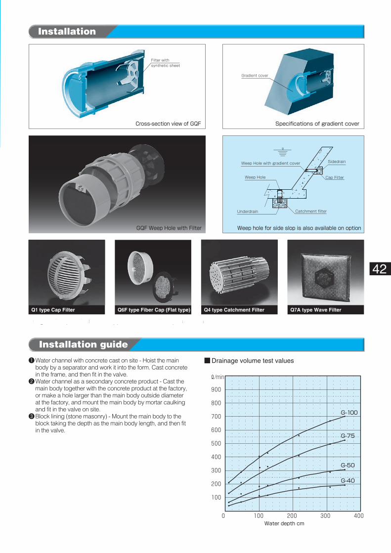
Water depth cm
G-100
G-75
G-50
G-40
■ Drainage volume test values
GQF�Weep�Hole�with�Filter
Specifications�of�gradient�coverCross-section�view�of�GQF
Weep�hole�for�side�slop�is�also�available�on�option
42
Q1 type Cap Filter Q6F type Fiber Cap (Flat type) Q4 type Catchment Filter Q7A type Wave Filter
❶�Water channel with concrete cast on site - Hoist the main body by a separator and work it into the form. Cast concrete in the frame, and then fit in the valve.
❷�Water channel as a secondary concrete product - Cast the main body together with the concrete product at the factory, or make a hole larger than the main body outside diameter at the factory, and mount the main body by mortar caulking and fit in the valve on site.
❸ Block lining (stone masonry) - Mount the main body to the block taking the depth as the main body length, and then fit in the valve.
Installation guide
Installation
Using the filter parts for the side opposite to valve of Weep-Hole would be recommended.
GSERIES
Valve screwFor GD-125 ‒ GD-150
Valve seat
Ribbed socketRubber valve
φAφC
φD
E
F
43
WEEP HOLEWEEP HOLE (GD type)
WEEP HOLE (GDL type)
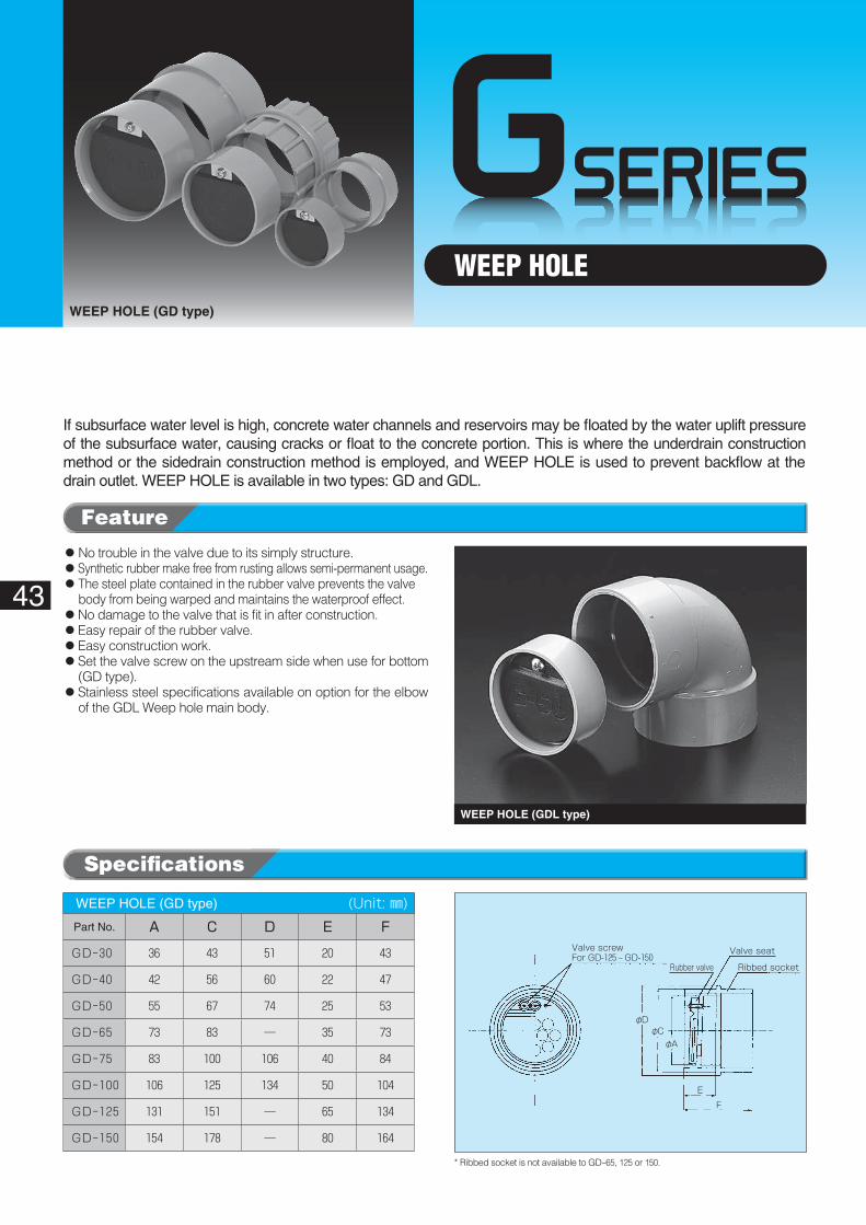
WEEP HOLE (GD type)� (Unit: ㎜)Part No. A C D E F
GD-30 36 43 51 20 43
GD-40 42 56 60 22 47
GD-50 55 67 74 25 53
GD-65 73 83 ― 35 73
GD-75 83 100 106 40 84
GD-100 106 125 134 50 104
GD-125 131 151 ― 65 134
GD-150 154 178 ― 80 164
If subsurface water level is high, concrete water channels and reservoirs may be floated by the water uplift pressure of the subsurface water, causing cracks or float to the concrete portion. This is where the underdrain construction method or the sidedrain construction method is employed, and WEEP HOLE is used to prevent backflow at the drain outlet. WEEP HOLE is available in two types: GD and GDL.
◦No trouble in the valve due to its simply structure.◦Synthetic rubber make free from rusting allows semi-permanent usage.◦�The steel plate contained in the rubber valve prevents the valve
body from being warped and maintains the waterproof effect.◦No damage to the valve that is fit in after construction.◦Easy repair of the rubber valve.◦Easy construction work.◦ Set the valve screw on the upstream side when use for bottom
(GD type).◦ Stainless steel specifications available on option for the elbow
of the GDL Weep hole main body.
* Ribbed socket is not available to GD-65, 125 or 150.
Specifications
Feature
Elbow
φBφC
K
Rubber valve
Valve seat
φAφB
φC
For GDL-125 ‒ GDL-150
Water flow
Filter with synthetic sheet
Water flow
Water depth cm
GD-100
GD-75
■ Drainage volume test values
WEEP�HOLE�(GD�type) WEEP�HOLE�(GDL�type)
44
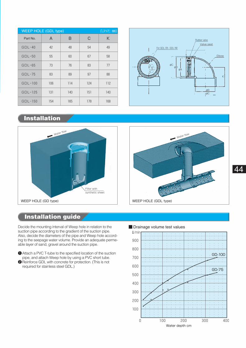
WEEP HOLE (GDL type)� (Unit: ㎜)
Part No. A B C K
GDL-40 42 48 54 49
GDL-50 55 60 67 58
GDL-65 73 76 83 77
GDL-75 83 89 97 88
GDL-100 106 114 124 112
GDL-125 131 140 151 140
GDL-150 154 165 178 168
Decide the mounting interval of Weep hole in relation to the suction pipe according to the gradient of the suction pipe. Also, decide the diameters of the pipe and Weep hole accord-ing to the seepage water volume. Provide an adequate perme-able layer of sand, gravel around the suction pipe.
❶�Attach a PVC T-tube to the specified location of the suction pipe, and attach Weep hole by using a PVC short tube.
❷�Reinforce GDL with concrete for protection. (This is not required for stainless steel GDL.)
Installation guide
Installation
GSERIES
φA
Existing PVC tube
L
φC
with synthetic sheet
Weep Hole for Inserts
Existing PVC tube Filter Q6F
GIU
45
WEEP HOLE (Insert type)WEEP HOLE (Insert type)
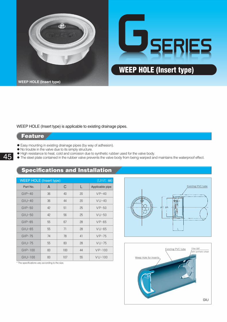
WEEP HOLE (Insert type)� (Unit: ㎜)Part No. A C L Applicable pipe
GIP-40 36 40 20 VP-40
GIU-40 36 44 20 VU-40
GIP-50 42 51 25 VP-50
GIU-50 42 56 25 VU-50
GIP-65 55 67 28 VP-65
GIU-65 55 71 28 VU-65
GIP-75 74 78 41 VP-75
GIU-75 55 83 28 VU-75
GIP-100 83 100 44 VP-100
GIU-100 83 107 55 VU-100
WEEP HOLE (Insert type) is applicable to existing drainage pipes.
◦Easy mounting in existing drainage pipes (by way of adhesion).◦No trouble in the valve due to its simply structure.◦High resistance to heat, cold and corrosion due to synthetic rubber used for the valve body.◦The steel plate contained in the rubber valve prevents the valve body from being warped and maintains the waterproof effect.
* The specifications vary according to the size.
Specifications and Installation
Feature
GSERIES
Z ZRubber valve
L
φA
φB
Filter B
Filter A
Screen filter Z-Z
tube withperforationHard PVC tube Hard PVC tube
Water flow Water flow
Water channel Water channel Secondary concrete Secondary concrete
Q6F filter
Type 1 Type 2
Weep Hole with ScreenWeep Hole with Screen
46
WEEP HOLE (with Screen)WEEP HOLE (with Screen)
WEEP HOLE (with Screen)� (Unit: ㎜)
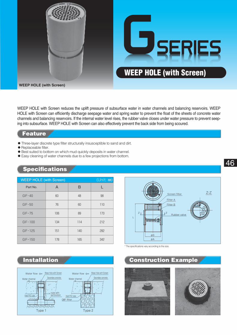
Part No. A B L
GF-40 60 48 98
GF-50 76 60 110
GF-75 106 89 173
GF-100 134 114 212
GF-125 151 140 282
GF-150 178 165 342
◦Three-layer discrete type filter structurally insusceptible to sand and dirt.◦Replaceable filter.◦Best suited to bottom on which mud quickly deposits in water channel.◦Easy cleaning of water channels due to a few projections from bottom.
WEEP HOLE with Screen reduces the uplift pressure of subsurface water in water channels and balancing reservoirs. WEEP HOLE with Screen can efficiently discharge seepage water and spring water to prevent the float of the sheets of concrete water channels and balancing reservoirs. If the internal water level rises, the rubber valve closes under water pressure to prevent seep-ing into subsurface. WEEP HOLE with Screen can also effectively prevent the back side from being scoured.
* The specifications vary according to the size.
Specifications
Feature
Construction ExampleInstallation
GSERIES
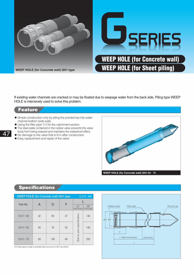
Rubber valve Filter pipe Pile end cap
φAφD
F
L1(Wall thickness) L2(Perforation)
L
47
WEEP HOLE (for Concrete wall) GH1 type
WEEP HOLE (for Concrete wall) GH1-50・75
WEEP HOLE (for Concrete wall) GH1 type� (Unit: ㎜)
Part No. A D FL
L1(Wall thickness)
L2(Porous length)
GH1-40 42 60 47
Siz
e to
you
r sp
ecifi
catio
n
140
GH1-50 55 76 53 140
GH1-75 83 106 84 200
If existing water channels are cracked or may be floated due to seepage water from the back side, Piling type WEEP HOLE is intensively used to solve this problem.
◦ Simple construction only by piling the pointed top into water channel bottom (side wall).
◦Using the filter pipe *(1) for the catchment section.◦ The steel plate contained in the rubber valve prevents the valve
body from being warped and maintains the waterproof effect.◦No damage to the valve that is fit in after construction.◦Easy replacement and repair of the valve.
*(1) Filter pipe is made of synthetic fiber (common to GH1 and GH2).
Specifications
Feature
WEEP HOLE (for Concrete wall)WEEP HOLE (for Sheet piling)
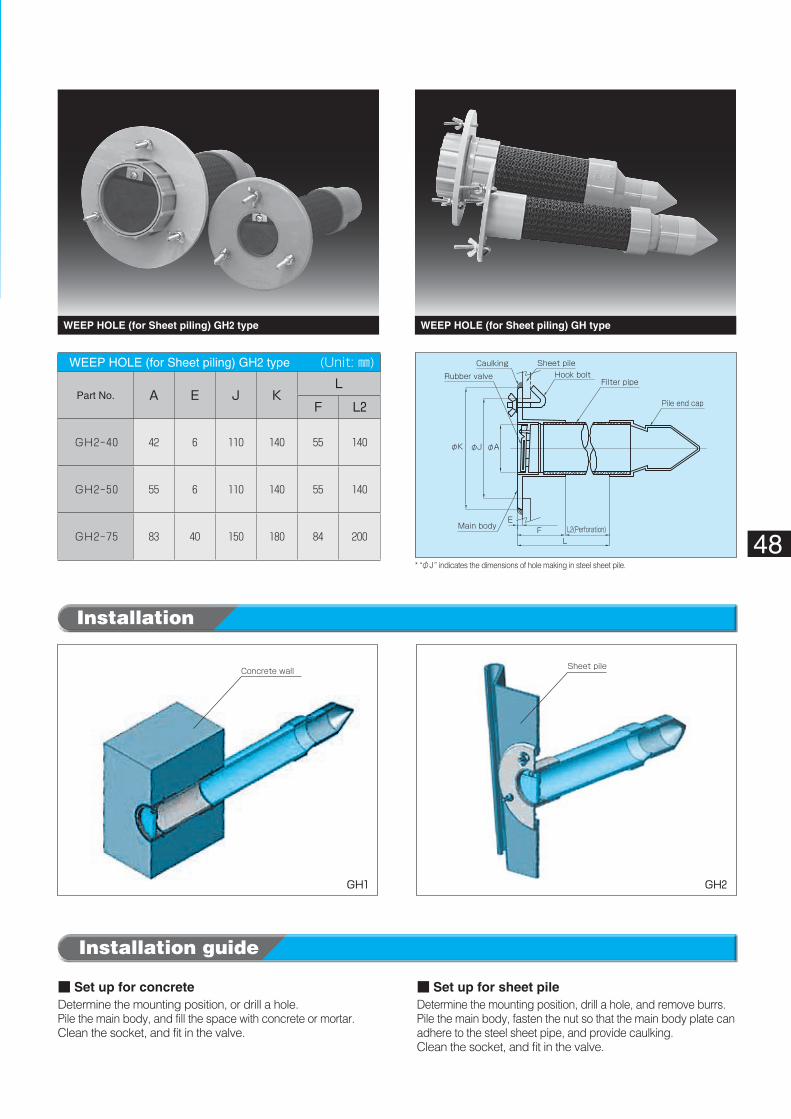
Pile end cap
φAφJ
F L2(Perforation)L
φK
E
Hook boltSheet pileCaulking
Rubber valve
Main body
Filter pipe
Concrete wall Sheet pile
GH1 GH2
48
Installation
WEEP HOLE (for Sheet piling) GH2 type� (Unit: ㎜)
Part No. A E J KL
F L2
GH2-40 42 6 110 140 55 140
GH2-50 55 6 110 140 55 140
GH2-75 83 40 150 180 84 200
WEEP HOLE (for Sheet piling) GH2 type WEEP HOLE (for Sheet piling) GH type
■ Set up for concreteDetermine the mounting position, or drill a hole.Pile the main body, and fill the space with concrete or mortar.Clean the socket, and fit in the valve.
* “φJ” indicates the dimensions of hole making in steel sheet pile.
■ Set up for sheet pileDetermine the mounting position, drill a hole, and remove burrs.Pile the main body, fasten the nut so that the main body plate can adhere to the steel sheet pipe, and provide caulking.Clean the socket, and fit in the valve.
Installation guide
GSERIES
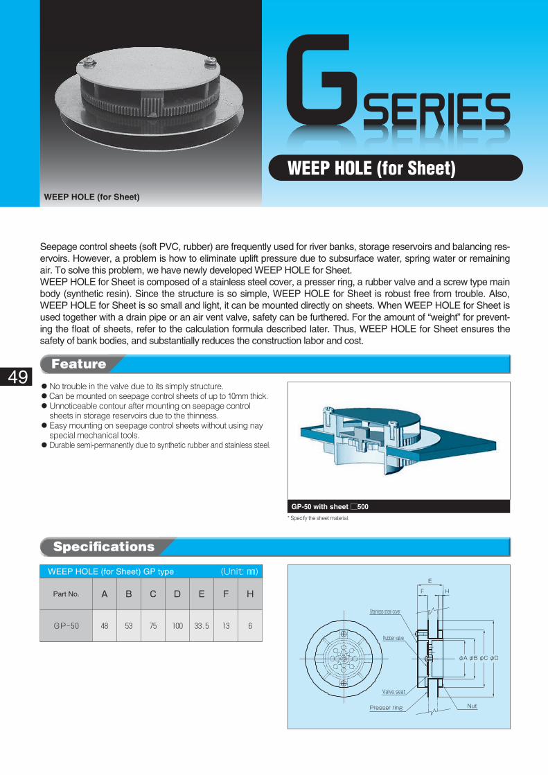
φAφB φC φD
F H
E
Stainless steel cover
Presser ring Nut
Rubber valve
Valve seat
GP-50 with sheet □500
49
WEEP HOLE (for Sheet)WEEP HOLE (for Sheet)
WEEP HOLE (for Sheet) GP type� (Unit: ㎜)
Part No. A B C D E F H
GP-50 48 53 75 100 33.5 13 6
Seepage control sheets (soft PVC, rubber) are frequently used for river banks, storage reservoirs and balancing res-ervoirs. However, a problem is how to eliminate uplift pressure due to subsurface water, spring water or remaining air. To solve this problem, we have newly developed WEEP HOLE for Sheet.WEEP HOLE for Sheet is composed of a stainless steel cover, a presser ring, a rubber valve and a screw type main body (synthetic resin). Since the structure is so simple, WEEP HOLE for Sheet is robust free from trouble. Also, WEEP HOLE for Sheet is so small and light, it can be mounted directly on sheets. When WEEP HOLE for Sheet is used together with a drain pipe or an air vent valve, safety can be furthered. For the amount of “weight” for prevent-ing the float of sheets, refer to the calculation formula described later. Thus, WEEP HOLE for Sheet ensures the safety of bank bodies, and substantially reduces the construction labor and cost.
◦No trouble in the valve due to its simply structure. ◦Can be mounted on seepage control sheets of up to 10mm thick.◦ Unnoticeable contour after mounting on seepage control
sheets in storage reservoirs due to the thinness.◦ Easy mounting on seepage control sheets without using nay
special mechanical tools.◦Durable semi-permanently due to synthetic rubber and stainless steel.
* Specify the sheet material.
Specifications
Feature
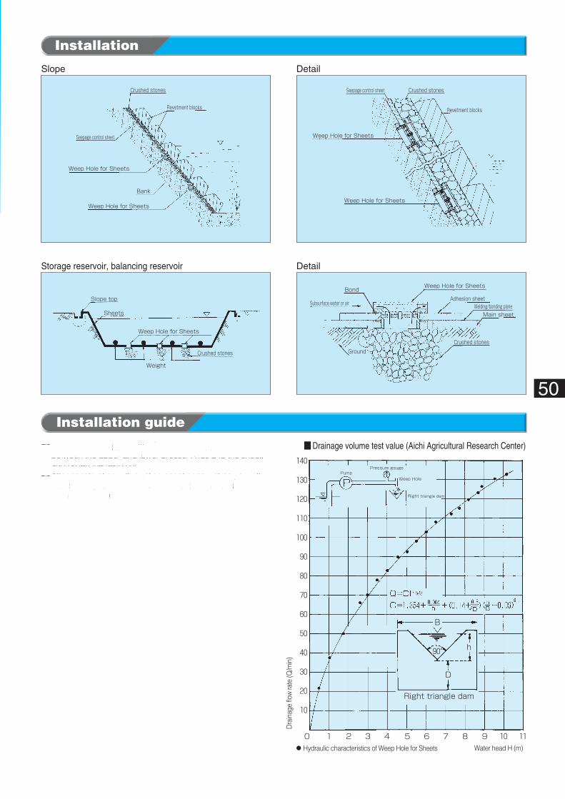
Weep Hole for Sheets
Seepage control sheet Crushed stones
Revetment blocks
Weep Hole for Sheets
Main sheetWelding/bonding plane
Adhesion sheetBond
Subsurface water or air
Ground
Weep Hole for Sheets
Crushed stones
Revetment blocks
Crushed stones
Seepage control sheet
Weep Hole for Sheets
Bank
Weep Hole for Sheets
Slope top
Sheets
Weight
Weep Hole for Sheets
Crushed stones
PumpPressure gauge
Weep Hole
Right triangle dam
Right triangle dam
B
D
h
Water head H (m)
Dra
inag
e flo
w ra
te (Q
/min
)
90°
140
130
120
110
100
90
80
70
60
50
40
30
20
10
70 1 2 3 4 5 6 8 9 10 11
■ Drainage volume test value (Aichi Agricultural Research Center)
◦Hydraulic characteristics of Weep Hole for Sheets
Slope
Storage reservoir, balancing reservoir
Detail
Detail
50
Installation
❶�Make a hole of approx. φ54 in the sheet, apply bond to between the upper and lower presser rings and the sheet, and fasten the resin nut.
❷�After construction with existing sheet or new sheet, cut off the sheet by approx. □300, pave crushed stones there, and mount GP-50 with sheet □500.
Installation guide
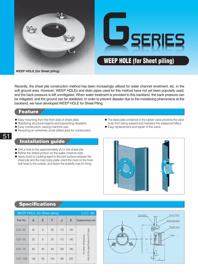
GSERIES
Caulking Sheet Piles
SUS hook bolt
Rubber valve
Filter
φAφJφK
EF
51
WEEP HOLE (for Sheet piling)WEEP HOLE (for Sheet piling)
WEEP HOLE (for Sheet piling)� (Unit: ㎜)
Part No. A E F J K Supplementary note
GS-40 42 6 55 110 140
For o
ther
dim
ensio
ns,
refe
r to
the
spec
ificat
ions
of G
type
.
GS-50 55 6 55 110 140
GS-75 83 40 84 150 180
GS-100 106 50 104 180 225
Recently, the sheet pile construction method has been increasingly utilized for water channel revetment, etc. in the soft ground area. However, WEEP HOLEs and drain pipes used for this method have not yet been popularly used, and the back pressure is left unmitigated. When water treatment is provided to this backland, the back pressure can be mitigated, and the ground can be stabilized. In order to prevent disaster due to the moistening phenomena at the backland, we have developed WEEP HOLE for Sheet Piling.
◦Easy mounting from the front side of sheet piles.◦Stabilizing structural objects and preventing disasters.◦Easy construction, saving machine use.◦Requiring an extremely small drilled area for construction.
◦ The steel plate contained in the rubber valve prevents the valve body from being warped and maintains the waterproof effect.
◦Easy replacement and repair of the valve.
◦Drill a hole to the approximately φJ in the sheet pile.◦Refine the drilled portion on the water channel side.◦ Apply bond or caulking agent to the joint surface between the
sheet pile and the main body plate, orient the mark on the hook bolt head to the outside, and fasten the butterfly nuts for fixing.
Specifications
Feature
Installation guide
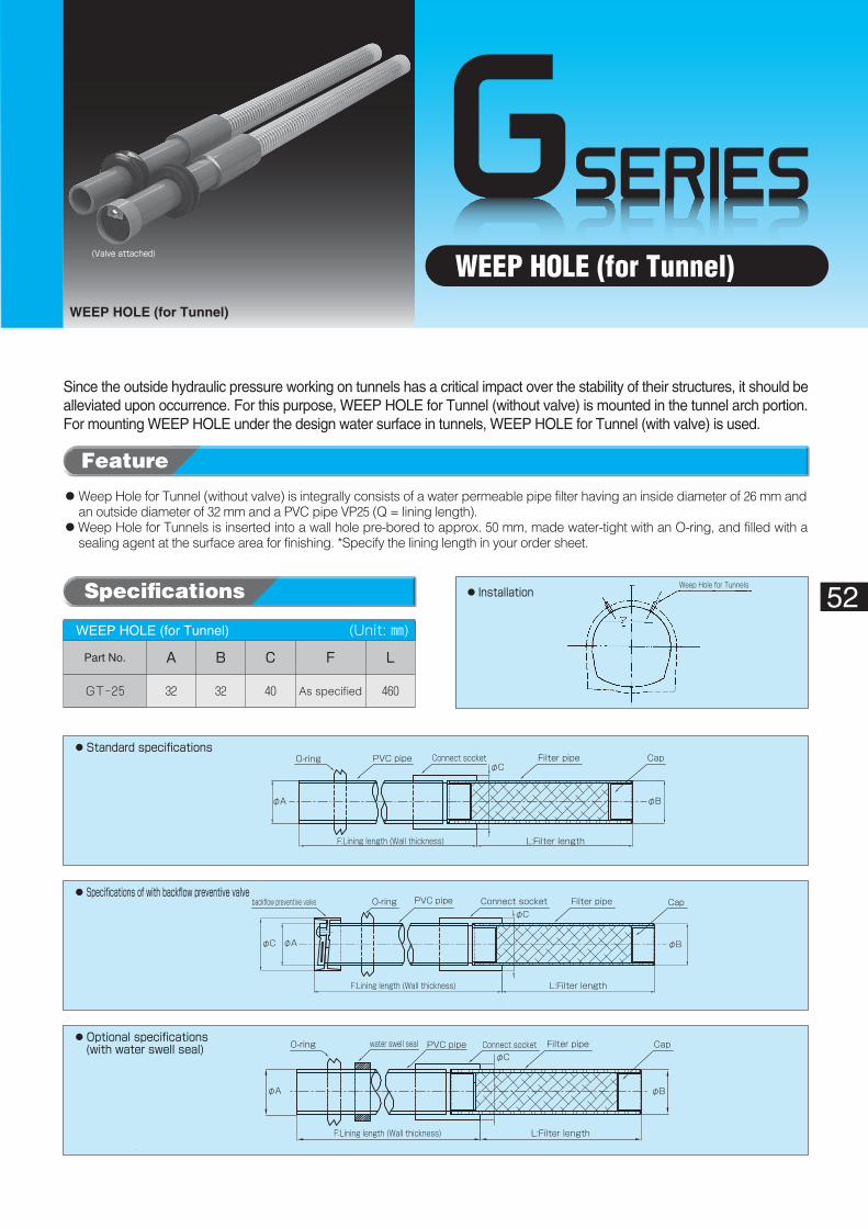
GSERIES
φA φB
φCFilter pipewater swell seal PVC pipeO-ring CapConnect socket
F:Lining length (Wall thickness) L:Filter length
φA φB
φCFilter pipePVC pipeO-ringbackflow preventive valve CapConnect socket
φC
F:Lining length (Wall thickness) L:Filter length
φA φB
φCFilter pipeConnect socketPVC pipeO-ring
F:Lining length (Wall thickness) L:Filter length
Cap
Weep Hole for Tunnels◦Installation
◦Standard�specifications
◦Specifications�of�with�backflow�preventive�valve
◦Optional�specifications(with�water�swell�seal)
(Valve�attached)
52
WEEP HOLE (for Tunnel)WEEP HOLE (for Tunnel)
WEEP HOLE (for Tunnel)� (Unit: ㎜)
Part No. A B C F L
GT-25 32 32 40 As specified 460
Since the outside hydraulic pressure working on tunnels has a critical impact over the stability of their structures, it should be alleviated upon occurrence. For this purpose, WEEP HOLE for Tunnel (without valve) is mounted in the tunnel arch portion. For mounting WEEP HOLE under the design water surface in tunnels, WEEP HOLE for Tunnel (with valve) is used.
◦�Weep Hole for Tunnel (without valve) is integrally consists of a water permeable pipe filter having an inside diameter of 26 mm and an outside diameter of 32 mm and a PVC pipe VP25 (Q = lining length).
◦�Weep Hole for Tunnels is inserted into a wall hole pre-bored to approx. 50 mm, made water-tight with an O-ring, and filled with a sealing agent at the surface area for finishing. *Specify the lining length in your order sheet.
Feature
Specifications
* On-site mounting work can be saved.
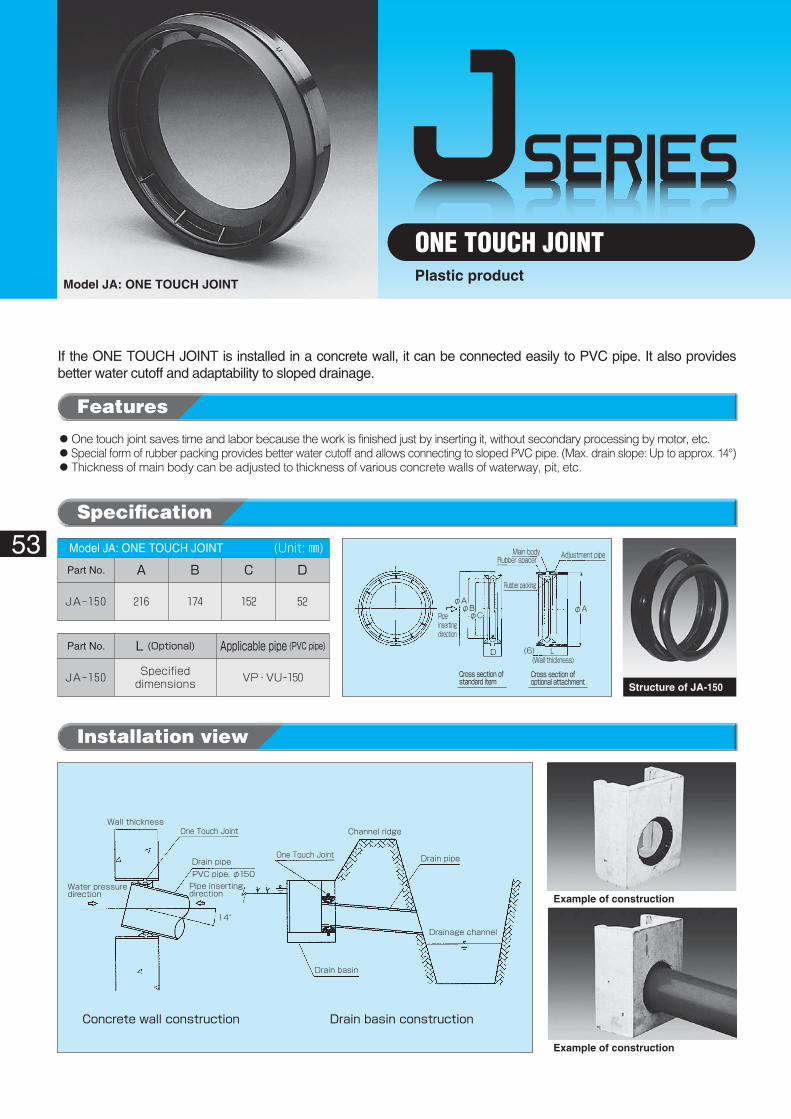
JSERIES
One Touch Joint
Water pressuredirection
Wall thickness
Drain basin
14°
Pipe insertingdirection
Drainage channel
Channel ridge
Concrete wall construction Drain basin construction
PVC pipe, φ150
Drain pipeDrain pipe
One Touch Joint
D (6)
Cross section ofstandard item
Cross section ofoptional attachment
L (Wall thickness)
Pipeinsertingdirection
Rubber packing
Rubber spacerMain body Adjustment pipe
φAφA
φCφB
53
ONE TOUCH JOINTModel JA: ONE TOUCH JOINT
Plastic product
If the ONE TOUCH JOINT is installed in a concrete wall, it can be connected easily to PVC pipe. It also provides better water cutoff and adaptability to sloped drainage.
Structure of JA-150
◦One touch joint saves time and labor because the work is finished just by inserting it, without secondary processing by motor, etc.◦Special form of rubber packing provides better water cutoff and allows connecting to sloped PVC pipe. (Max. drain slope: Up to approx. 14°)◦ Thickness of main body can be adjusted to thickness of various concrete walls of waterway, pit, etc.
Installation view
Model JA: ONE TOUCH JOINT� (Unit: ㎜)Part No. A B C D
JA-150 216 174 152 52
Part No. L�(Optional) Applicable�pipe�(PVC�pipe)
JA-150 Specifieddimensions VP・VU-150
Example of construction
Example of construction
Features
Specification
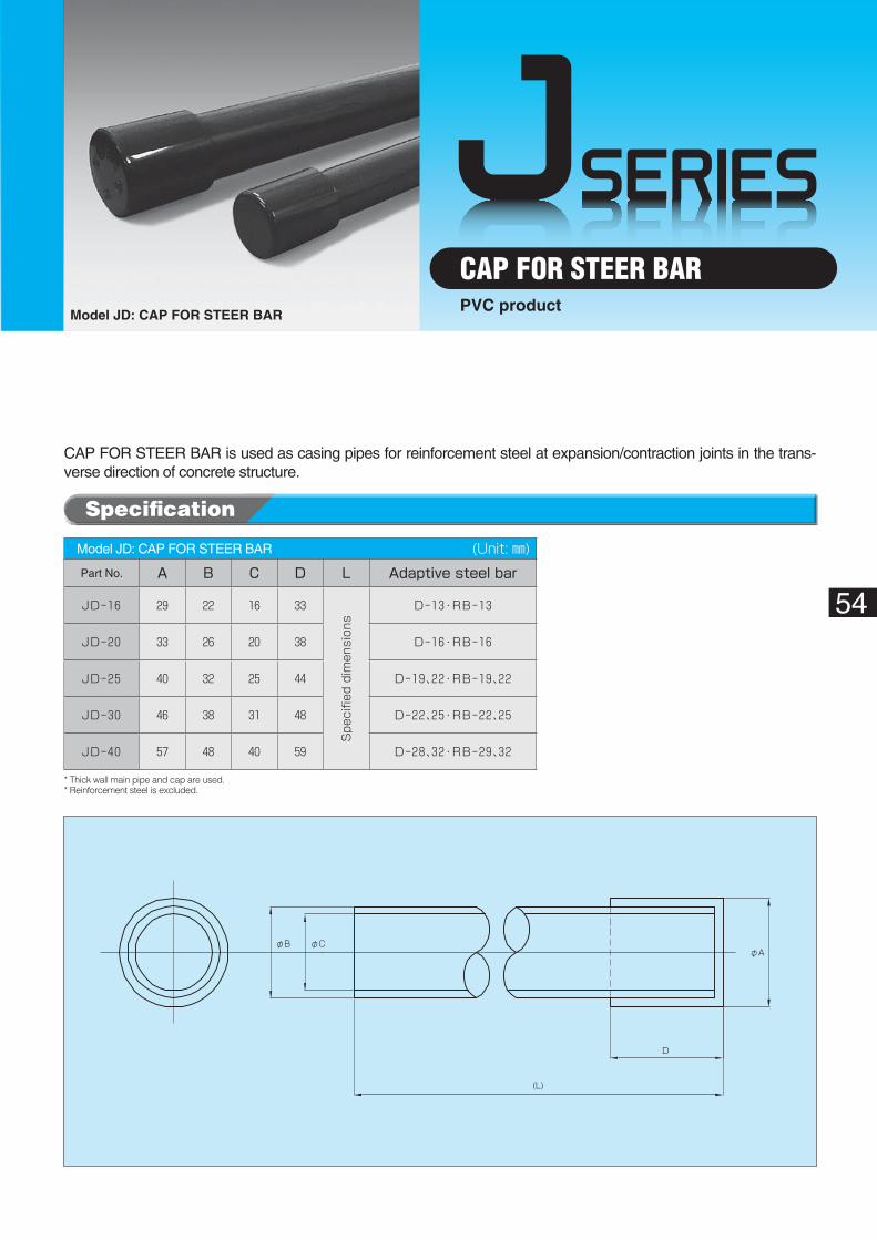
JSERIES
φAφB φC
D
(L)
54
Model JD: CAP FOR STEER BAR
CAP FOR STEER BARPVC product
CAP FOR STEER BAR is used as casing pipes for reinforcement steel at expansion/contraction joints in the trans-verse direction of concrete structure.
Model JD: CAP FOR STEER BAR� (Unit: ㎜)Part No. A B C D L Adaptive�steel�bar
JD-16 29 22 16 33
Spe
cifie
d dimen
sion
s
D-13・RB-13
JD-20 33 26 20 38 D-16・RB-16
JD-25 40 32 25 44 D-19、22・RB-19、22
JD-30 46 38 31 48 D-22、25・RB-22、25
JD-40 57 48 40 59 D-28、32・RB-29、32
* Thick wall main pipe and cap are used.* Reinforcement steel is excluded.
Specification
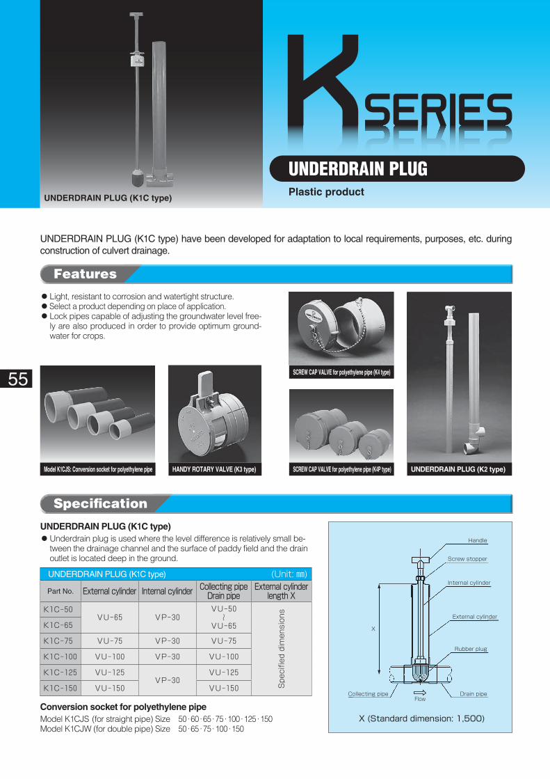
KSERIES
Handle
Screw stopper
Internal cylinder
External cylinder
Drain pipe
Rubber plug
Collecting pipe
X (Standard dimension: 1,500)
X
Flow
55
UNDERDRAIN PLUG (K1C type)
UNDERDRAIN PLUGPlastic product
UNDERDRAIN PLUG (K1C type) have been developed for adaptation to local requirements, purposes, etc. during construction of culvert drainage.
UNDERDRAIN PLUG (K2 type)SCREW CAP VALVE for polyethylene pipe (K4P type)Model K1CJS: Conversion socket for polyethylene pipe HANDY ROTARY VALVE (K3 type)
SCREW CAP VALVE for polyethylene pipe (K4 type)
◦Light, resistant to corrosion and watertight structure.◦��Select a product depending on place of application.◦ Lock pipes capable of adjusting the groundwater level free-
ly are also produced in order to provide optimum ground-water for crops.
UNDERDRAIN PLUG (K1C type)� (Unit: ㎜)
Part No. External�cylinder Internal�cylinder Collecting�pipeDrain�pipe
External�cylinder�length�X
K1C-50VU-65 VP-30
VU-50~
VU-65
Spe
cifie
d dimen
sion
s
K1C-65
K1C-75 VU-75 VP-30 VU-75
K1C-100 VU-100 VP-30 VU-100
K1C-125 VU-125VP-30
VU-125
K1C-150 VU-150 VU-150
UNDERDRAIN PLUG (K1C type)◦��Underdrain plug is used where the level difference is relatively small be-
tween the drainage channel and the surface of paddy field and the drain outlet is located deep in the ground.
Conversion socket for polyethylene pipe��Model K1CJS (for straight pipe) Size 50·60·65·75·100·125·150Model K1CJW (for double pipe) Size 50·65·75·100·150
Specification
Features
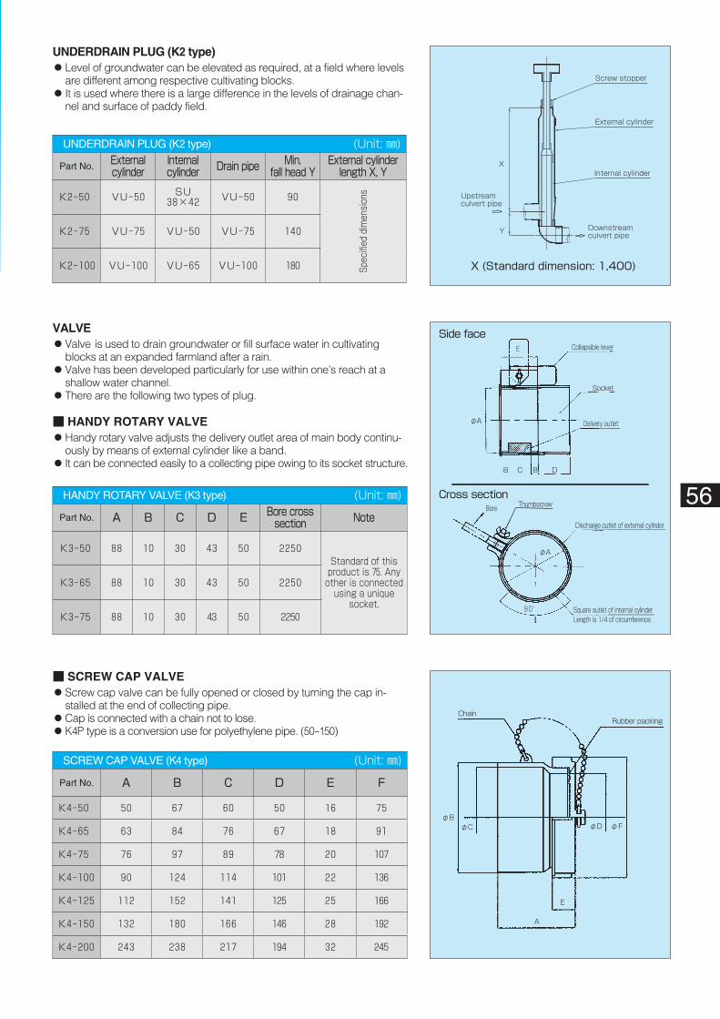
Screw stopper
External cylinder
Internal cylinder
X (Standard dimension: 1,400)
Upstreamculvert pipe
X
Y Downstreamculvert pipe
Collapsible lever
Side face
Socket
Delivery outlet
E
B C B D
φA
Cross sectionBore Thumbscrew
Discharge outlet of external cylinder
Square outlet of internal cylinderLength is 1/4 of circumference.
φA
90°
ChainRubber packing
A
E
φFφDφCφB
56
UNDERDRAIN PLUG (K2 type)� (Unit: ㎜)
Part No. Externalcylinder
Internalcylinder Drain�pipe Min.�
fall�head�YExternal�cylinder�
length�X,�Y
K2-50 VU-50 SU38×42 VU-50 90
Spec
ified
dim
ension
s
K2-75 VU-75 VU-50 VU-75 140
K2-100 VU-100 VU-65 VU-100 180
UNDERDRAIN PLUG (K2 type)◦��Level of groundwater can be elevated as required, at a field where levels
are different among respective cultivating blocks.◦��It is used where there is a large difference in the levels of drainage chan-
nel and surface of paddy field.
HANDY ROTARY VALVE (K3 type)� (Unit: ㎜)
Part No. A B C D E Bore�cross�section Note
K3-50 88 10 30 43 50 2250Standard of this product is 75. Any other is connected
using a unique socket.
K3-65 88 10 30 43 50 2250
K3-75 88 10 30 43 50 2250
SCREW CAP VALVE (K4 type)� (Unit: ㎜)
Part No. A B C D E F
K4-50 50 67 60 50 16 75
K4-65 63 84 76 67 18 91
K4-75 76 97 89 78 20 107
K4-100 90 124 114 101 22 136
K4-125 112 152 141 125 25 166
K4-150 132 180 166 146 28 192
K4-200 243 238 217 194 32 245
VALVE◦��Valve is used to drain groundwater or fill surface water in cultivating
blocks at an expanded farmland after a rain.◦��Valve has been developed particularly for use within one’s reach at a
shallow water channel.◦��There are the following two types of plug.
■ HANDY ROTARY VALVE◦��Handy rotary valve adjusts the delivery outlet area of main body continu-
ously by means of external cylinder like a band.◦��It can be connected easily to a collecting pipe owing to its socket structure.
■ SCREW CAP VALVE◦��Screw cap valve can be fully opened or closed by turning the cap in-
stalled at the end of collecting pipe.◦��Cap is connected with a chain not to lose.◦��K4P type is a conversion use for polyethylene pipe. (50-150)
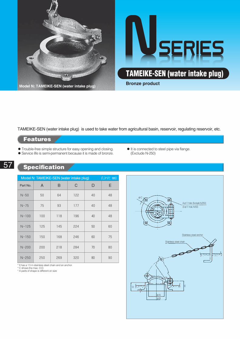
NSERIES
4-φ11 hole (Exclude N-250)
ED
φA
φC
φB
(3-φ11 hole, N-50)
Stainless steel chain
Stainless steel anchor
57
Model N: TAMEIKE-SEN (water intake plug)
TAMEIKE-SEN (water intake plug)Bronze product
TAMEIKE-SEN (water intake plug) is used to take water from agricultural basin, reservoir, regulating reservoir, etc.
◦Trouble-free simple structure for easy opening and closing.◦Service life is semi-permanent because it is made of bronze.
◦��It is connected to steel pipe via flange.(Exclude N-250)
Model N: TAMEIKE-SEN (water intake plug)� (Unit: ㎜)
Part No. A B C D E
N-50 50 64 122 40 48
N-75 75 93 177 40 48
N-100 100 118 196 40 48
N-125 125 145 224 50 60
N-150 150 168 246 60 75
N-200 200 218 284 70 80
N-250 250 269 320 80 90
* It has a 1.5 m stainless steel chain and an anchor.* C shows the max. O.D.* A parts of shape is different on size
Features
Specification
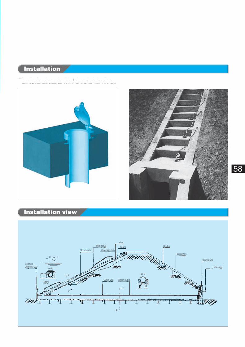
Sediment discharge door
Stairs
Sloped gutter
Intake plug
Operating chain
Vent
Stairs Old dike
Planned dike
Retaining wall
Drain pipe
Cutoff wall Bottom gutter
H・W・L
A-A
B-B
B
B
A
A
58
Installation
Installation view
◦��Install it oriented upward and along the angle of slope face, and line the gate sheet section (by approx. half) with concrete.
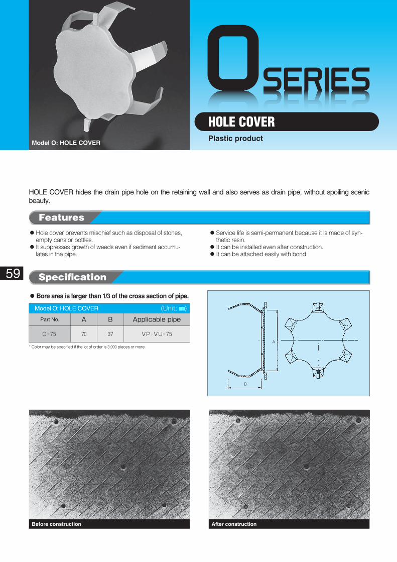
OSERIES
A
B
59
Model O: HOLE COVER
HOLE COVERPlastic product
HOLE COVER hides the drain pipe hole on the retaining wall and also serves as drain pipe, without spoiling scenic beauty.
Before construction After construction
◦��Hole cover prevents mischief such as disposal of stones, empty cans or bottles.
◦��It suppresses growth of weeds even if sediment accumu-lates in the pipe.
◦��Service life is semi-permanent because it is made of syn-thetic resin.
◦��It can be installed even after construction.◦��It can be attached easily with bond.
◦Bore area is larger than 1/3 of the cross section of pipe.
Model O: HOLE COVER� (Unit: ㎜)Part No. A B Applicable�pipe
O-75 70 37 VP・VU-75
* Color may be specified if the lot of order is 3,000 pieces or more.
Specification
Features
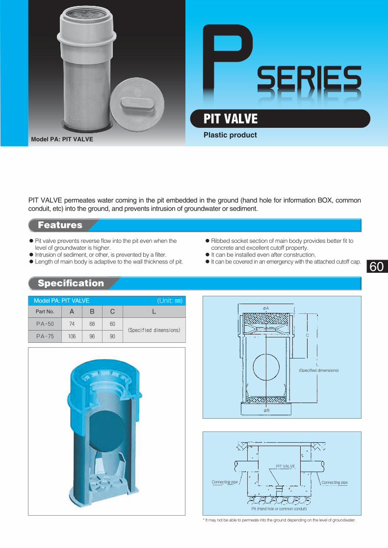
PSERIES
Connecting pipe
PIT VALVE
Connecting pipe
Pit (Hand hole or common conduit)
(Specified dimensions)L
C
φA
φB
60
PIT VALVEModel PA: PIT VALVE
Plastic product
PIT VALVE permeates water coming in the pit embedded in the ground (hand hole for information BOX, common conduit, etc) into the ground, and prevents intrusion of groundwater or sediment.
◦��Pit valve prevents reverse flow into the pit even when the level of groundwater is higher.
◦ Intrusion of sediment, or other, is prevented by a filter.◦��Length of main body is adaptive to the wall thickness of pit.
◦��Ribbed socket section of main body provides better fit to concrete and excellent cutoff property.
◦��It can be installed even after construction.◦��It can be covered in an emergency with the attached cutoff cap.
Model PA: PIT VALVE� (Unit: ㎜)Part No. A B C L
PA-50 74 68 60(Specified dimensions)
PA-75 106 96 90
* It may not be able to permeate into the ground depending on the level of groundwater.
Features
Specification
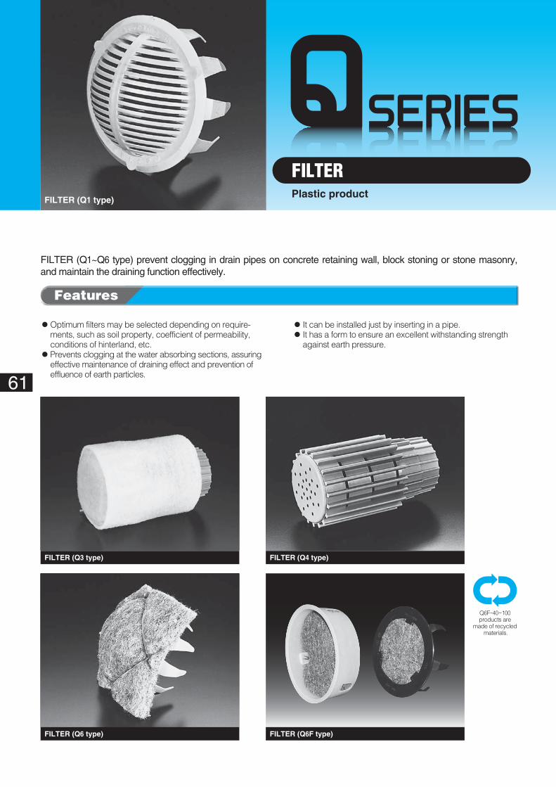
61
FILTER (Q1 type)
FILTERPlastic product
FILTER (Q1~Q6 type) prevent clogging in drain pipes on concrete retaining wall, block stoning or stone masonry, and maintain the draining function effectively.
FILTER (Q6 type)
FILTER (Q3 type)
FILTER (Q6F type)
FILTER (Q4 type)
◦��Optimum filters may be selected depending on require-ments, such as soil property, coefficient of permeability, conditions of hinterland, etc.
◦��Prevents clogging at the water absorbing sections, assuring effective maintenance of draining effect and prevention of effluence of earth particles.
◦��It can be installed just by inserting in a pipe.◦��It has a form to ensure an excellent withstanding strength
against earth pressure.
Q6F-40~100products are
made of recycled materials.
Features
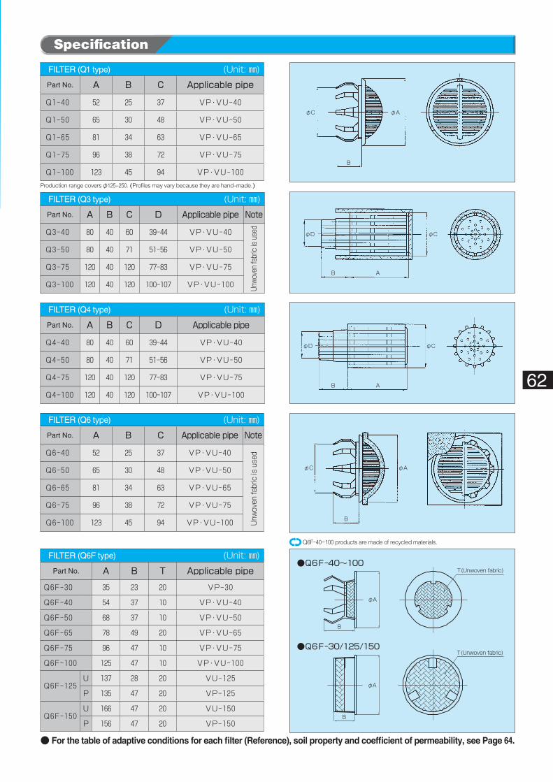
●Q6F-40~100
●Q6F-30/125/150
T(Unwoven fabric)
T(Unwoven fabric)
φA
φA
B
B
φAφC
B
φD φC
B A
φD φC
B A
φAφC
B
Production range covers φ125-250. (Profiles may vary because they are hand-made.)
62
Q6F-40~100 products are made of recycled materials.
FILTER (Q1 type)� (Unit: ㎜)Part No. A B C Applicable�pipe
Q1-40 52 25 37 VP・VU-40
Q1-50 65 30 48 VP・VU-50
Q1-65 81 34 63 VP・VU-65
Q1-75 96 38 72 VP・VU-75
Q1-100 123 45 94 VP・VU-100
FILTER (Q6F type)� (Unit: ㎜)Part No. A B T Applicable�pipe
Q6F-30 35 23 20 VP-30
Q6F-40 54 37 10 VP・VU-40
Q6F-50 68 37 10 VP・VU-50
Q6F-65 78 49 20 VP・VU-65
Q6F-75 96 47 10 VP・VU-75
Q6F-100 125 47 10 VP・VU-100
Q6F-125U 137 28 20 VU-125
P 135 47 20 VP-125
Q6F-150U 166 47 20 VU-150
P 156 47 20 VP-150
FILTER (Q3 type)� (Unit: ㎜)Part No. A B C D Applicable�pipe Note
Q3-40 80 40 60 39-44 VP・VU-40
Q3-50 80 40 71 51-56 VP・VU-50
Q3-75 120 40 120 77-83 VP・VU-75
Q3-100 120 40 120 100-107 VP・VU-100
FILTER (Q6 type)� (Unit: ㎜)Part No. A B C Applicable�pipe Note
Q6-40 52 25 37 VP・VU-40
Q6-50 65 30 48 VP・VU-50
Q6-65 81 34 63 VP・VU-65
Q6-75 96 38 72 VP・VU-75
Q6-100 123 45 94 VP・VU-100
Unwo
ven fabric
is us
edUnw
oven
fabric is
use
d
● For the table of adaptive conditions for each filter (Reference), soil property and coefficient of permeability, see Page 64.
FILTER (Q4 type)� (Unit: ㎜)Part No. A B C D Applicable�pipe
Q4-40 80 40 60 39-44 VP・VU-40
Q4-50 80 40 71 51-56 VP・VU-50
Q4-75 120 40 120 77-83 VP・VU-75
Q4-100 120 40 120 100-107 VP・VU-100
Specification
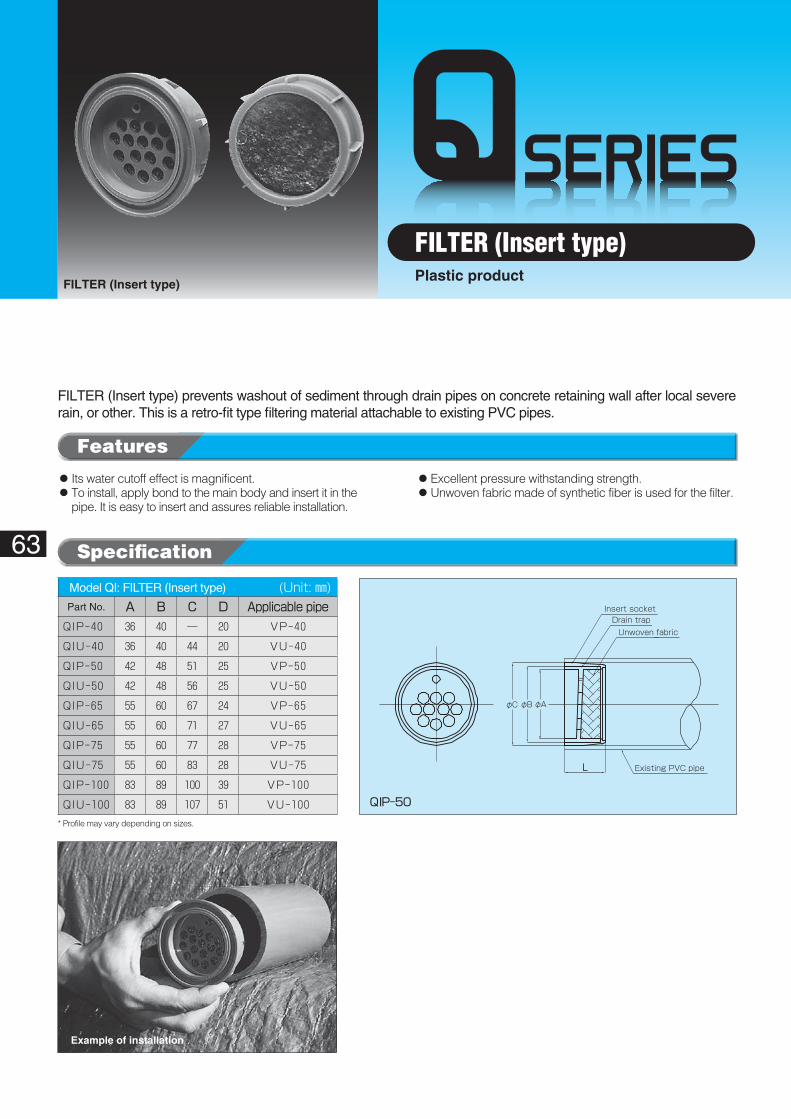
QIP-50
L
φA
Insert socket
Unwoven fabricDrain trap
Existing PVC pipe
φBφC
* Profile may vary depending on sizes.
63
FILTER (Insert type)
FILTER (Insert type)Plastic product
FILTER (Insert type) prevents washout of sediment through drain pipes on concrete retaining wall after local severe rain, or other. This is a retro-fit type filtering material attachable to existing PVC pipes.
◦��Its water cutoff effect is magnificent.◦��To install, apply bond to the main body and insert it in the
pipe. It is easy to insert and assures reliable installation.
◦��Excellent pressure withstanding strength.◦��Unwoven fabric made of synthetic fiber is used for the filter.
Example of installation
Model QI: FILTER (Insert type)� (Unit: ㎜)Part No. A B C D Applicable�pipeQIP-40 36 40 ― 20 VP-40
QIU-40 36 40 44 20 VU-40
QIP-50 42 48 51 25 VP-50
QIU-50 42 48 56 25 VU-50
QIP-65 55 60 67 24 VP-65
QIU-65 55 60 71 27 VU-65
QIP-75 55 60 77 28 VP-75
QIU-75 55 60 83 28 VU-75
QIP-100 83 89 100 39 VP-100
QIU-100 83 89 107 51 VU-100
Specification
Features
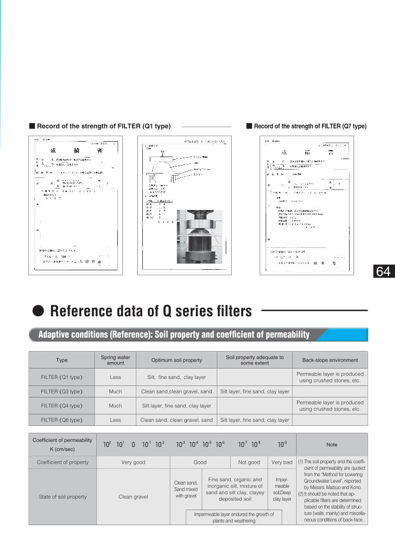
64
Adaptive conditions (Reference): Soil property and coefficient of permeability
Coefficient of permeability
K (cm/sec)102 101 0 10-1 10-2 10-3 10-4 10-5 10-6 10-7 10-8 10-9 Note
Coefficient of property Very good Good Not good Very bad
State of soil property Clean gravel
Clean sand,Sand mixedwith gravel
Fine sand, organic and inorganic silt, mixture of
sand and silt clay, clayey deposited soil
Imper-meable
soil,Deep clay layer
Impermeable layer endured the growth ofplants and weathering
(1) The soil property and the coeffi-cient of permeability are quoted from the “Method for Lowering Groundwater Level”, reported by Messrs. Matsuo and Kono.
(2) It should be noted that ap-plicable filters are determined based on the stability of struc-ture (walls, mainly) and miscella-neous conditions of back-face.
Type Spring water amount Optimum soil property Soil property adequate to
some extent Back-slope environment
FILTER (Q1 type) Less Silt, fine sand, clay layerPermeable layer is produced using crushed stones, etc.
FILTER (Q3 type) Much Clean sand,clean gravel, sand Silt layer, fine sand, clay layer
FILTER (Q4 type) Much Silt layer, fine sand, clay layerPermeable layer is produced using crushed stones, etc.
FILTER (Q6 type) Less Clean sand, clean gravel, sand Silt layer, fine sand, clay layer
■ Record of the strength of FILTER (Q1 type) ■ Record of the strength of FILTER (Q7 type)
◦Reference data of Q series filters
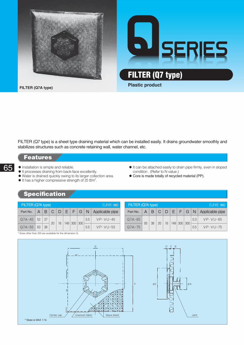
F
DG C B
φE φA
Wave sheetCenter cap Unwoven fabric Joint
* Slope is MAX 1: N.
65
FILTER (Q7A type)
FILTER (Q7 type)Plastic product
FILTER (Q7 type) is a sheet type draining material which can be installed easily. It drains groundwater smoothly and stabilizes structures such as concrete retaining wall, water channel, etc.
◦��Installation is simple and reliable.◦��It processes draining from back-face excellently.◦��Water is drained quickly owing to its larger collection area.◦��It has a higher compressive strength of 25 tf/m2.
◦��It can be attached easily to drain pipe firmly, even in sloped condition . (Refer to N value.)
◦��Core is made totally of recycled material (PP).
FILTER (Q7A type)� (Unit: ㎜)Part No. A B C D E F G N Applicable�pipe
Q7A-40 52 3720 16 149 300 300
0.5 VP・VU-40
Q7A-50 63 38 0.5 VP・VU-50
FILTER (Q7A type)� (Unit: ㎜)Part No. A B C D E F G N Applicable�pipe
Q7A-6593 38 20 16 149 300 300
0.3 VP・VU-65
Q7A-75 0.5 VP・VU-75
* Sizes other than 300 are available for the dimension G.
Features
Specification
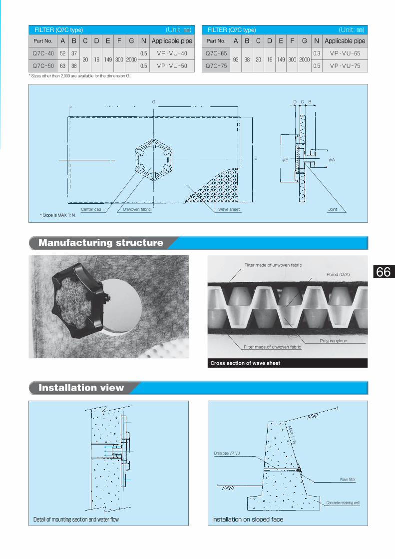
Detail of mounting section and water flow
Drain pipe VP, VU
Wave filter
MAX 1 : N
Concrete retaining wall
Installation on sloped face
DG C B
φA
Wave sheetCenter cap Unwoven fabric Joint
φEF
* Slope is MAX 1: N.
Filter made of unwoven fabric
Filter made of unwoven fabric
Pored (Q7A)
Polypropylene
66
Installation view
Manufacturing structure
Structure of FILTER (Q7 type) Cross section of wave sheet
FILTER (Q7C type)� (Unit: ㎜)Part No. A B C D E F G N Applicable�pipe
Q7C-40 52 3720 16 149 300 2000
0.5 VP・VU-40
Q7C-50 63 38 0.5 VP・VU-50
FILTER (Q7C type)� (Unit: ㎜)Part No. A B C D E F G N Applicable�pipe
Q7C-6593 38 20 16 149 300 2000
0.3 VP・VU-65
Q7C-75 0.5 VP・VU-75
* Sizes other than 2,000 are available for the dimension G.
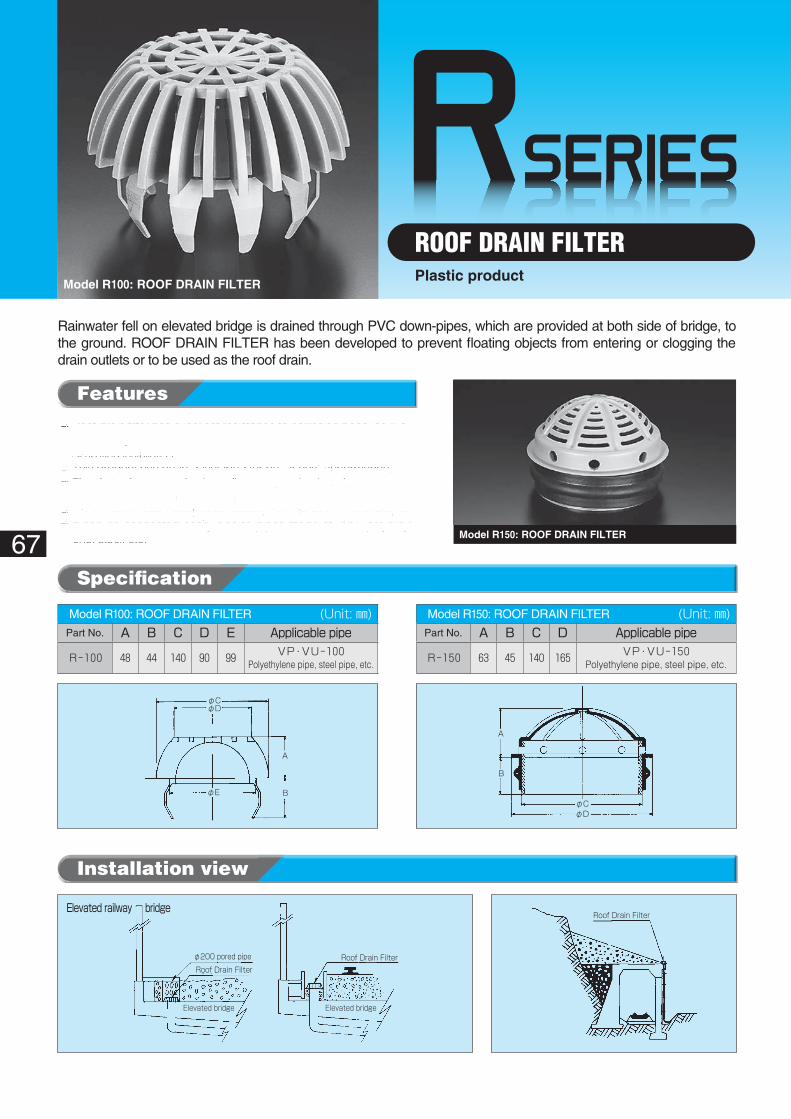
RSERIES
φ200 pored pipe
Roof Drain FilterRoof Drain Filter
Elevated bridge Elevated bridge
Elevated railway bridge
φCφD
φE
A
B
Roof Drain Filter
φCφD
A
B
67
Model R100: ROOF DRAIN FILTER
ROOF DRAIN FILTERPlastic product
Model R150: ROOF DRAIN FILTER
Rainwater fell on elevated bridge is drained through PVC down-pipes, which are provided at both side of bridge, to the ground. ROOF DRAIN FILTER has been developed to prevent floating objects from entering or clogging the drain outlets or to be used as the roof drain.
Installation view
◦��Roof drain filter has excellent resistance to corrosion because it is made of synthetic resin.
◦��Simplified installation.◦ This product has been developed for better cost performance.◦ The drain shows excellent sturdiness against external pressure ow-
ing to its arched profile at the top.◦ It is formed to keep away fallen leaves, torn pieces of vinyl sheet, etc.◦ It can be connected easily also to pipes made of PVC, polyethyl-
ene, steel, etc.
Model R100: ROOF DRAIN FILTER� (Unit: ㎜)Part No. A B C D E Applicable�pipe
R-100 48 44 140 90 99 VP・VU-100Polyethylene pipe, steel pipe, etc.
Model R150: ROOF DRAIN FILTER� (Unit: ㎜)Part No. A B C D Applicable�pipe
R-150 63 45 140 165 VP・VU-150Polyethylene pipe, steel pipe, etc.
Specification
Features
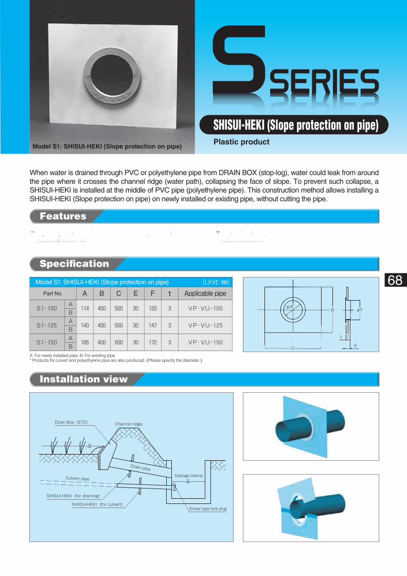
SSERIES
Channel ridge
SHISUI-HEKI (for draining)
SHISUI-HEKI (for culvert)
Drainage channel
Screw type lock plug
Drain pipe
Drain Box(ET2)
Culvert pipe
φAφFB
E
t
C
68
SHISUI-HEKI (Slope protection on pipe)Model S1: SHISUI-HEKI (Slope protection on pipe)
Plastic product
When water is drained through PVC or polyethylene pipe from DRAIN BOX (stop-log), water could leak from around the pipe where it crosses the channel ridge (water path), collapsing the face of slope. To prevent such collapse, a SHISUI-HEKI is installed at the middle of PVC pipe (polyethylene pipe). This construction method allows installing a SHISUI-HEKI (Slope protection on pipe) on newly installed or existing pipe, without cutting the pipe.
Installation view
◦��Light, highly resistant to corrosion and easy for mainte-nance and control.
◦��Installation is simplified because it can be connected to a pipe quite easily.
A- For newly installed pipes
B- For existing pipes
Model S1: SHISUI-HEKI (Slope protection on pipe)� (Unit: ㎜)Part No. A B C E F t Applicable�pipe
S1-100A
114 400 500 30 120 3 VP・VU-100B
S1-125A
140 400 500 30 147 3 VP・VU-125B
S1-150A
165 400 500 30 172 3 VP・VU-150B
A: For newly installed pipe, B: For existing pipe* Products for culvert and polyethylene pipe are also produced. (Please specify the diameter.)
Features
Specification
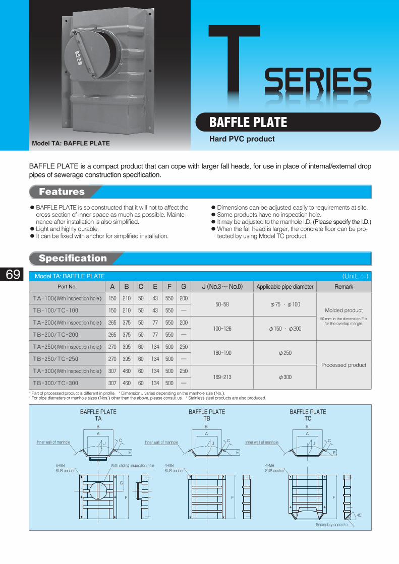
TSERIES
6-M8SUS anchor
4-M8SUS anchor
4-M8SUS anchor
Inner wall of manhole
Secondary concrete
45°
FFF
G
E
B
A
JC
E
B
A
JC
E
B
A
JC Inner wall of manhole
With sliding inspection hole
Inner wall of manhole
BAFFLE PLATETA
BAFFLE PLATETB
BAFFLE PLATETC
69
Model TA: BAFFLE PLATE
BAFFLE PLATEHard PVC product
BAFFLE PLATE is a compact product that can cope with larger fall heads, for use in place of internal/external drop pipes of sewerage construction specification.
◦��BAFFLE PLATE is so constructed that it will not to affect the cross section of inner space as much as possible. Mainte-nance after installation is also simplified.
◦��Light and highly durable.◦��It can be fixed with anchor for simplified installation.
◦��Dimensions can be adjusted easily to requirements at site.◦��Some products have no inspection hole.◦��It may be adjusted to the manhole I.D. (Please specify the I.D.)◦��When the fall head is larger, the concrete floor can be pro-
tected by using Model TC product.
Model TA: BAFFLE PLATE� (Unit: ㎜)Part No. A B C E F G J(No.3~No.0) Applicable pipe diameter Remark
TA-100(With inspection hole) 150 210 50 43 550 20050-58 φ75 ・ φ100
Molded product
50 mm in the dimension F isfor the overlap margin.
TB-100/TC-100 150 210 50 43 550 ―
TA-200(With inspection hole) 265 375 50 77 550 200100-126 φ150 ・ φ200
TB-200/TC-200 265 375 50 77 550 ―
TA-250(With inspection hole) 270 395 60 134 500 250160-190 φ250
Processed productTB-250/TC-250 270 395 60 134 500 ―
TA-300(With inspection hole) 307 460 60 134 500 250169-213 φ300
TB-300/TC-300 307 460 60 134 500 ―
* Part of processed product is different in profile. * Dimension J varies depending on the manhole size (No.).* For pipe diameters or manhole sizes (Nos.) other than the above, please consult us. * Stainless steel products are also produced.
Features
Specification
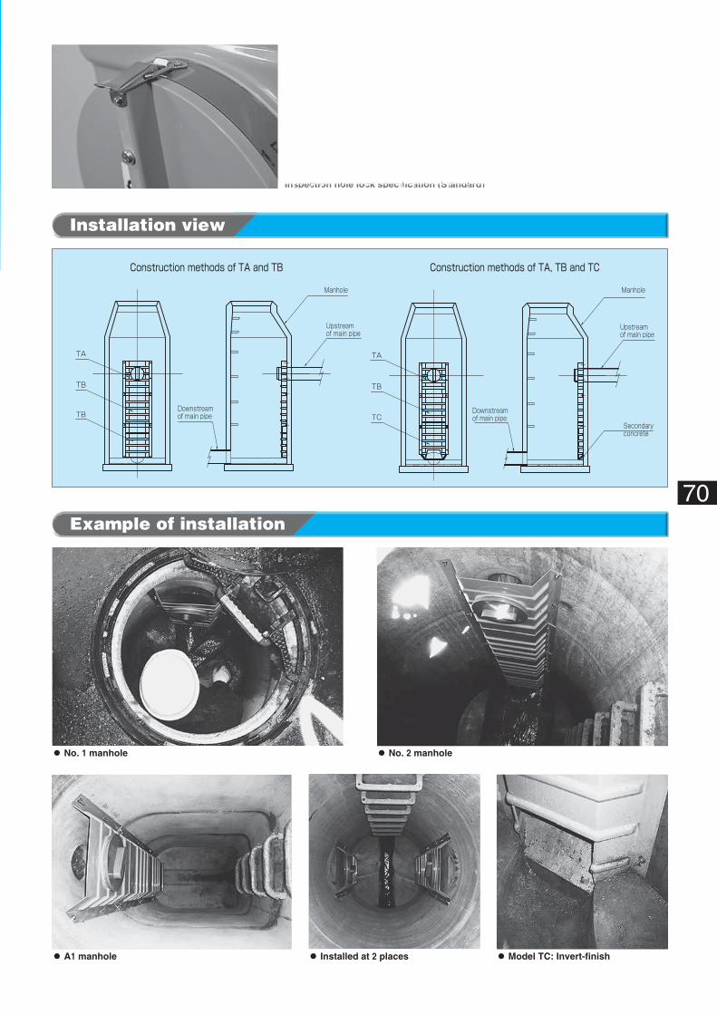
TA
Downstreamof main pipe
Downstreamof main pipe
Secondaryconcrete
Upstreamof main pipe
Upstreamof main pipe
Manhole Manhole
TB
TB
Construction methods of TA and TB Construction methods of TA, TB and TC
TA
TB
TC
◦ No. 1 manhole
◦ A1 manhole ◦ Installed at 2 places ◦ Model TC: Invert-finish
◦ No. 2 manhole
70
Installation view
Example of installation
Inspection hole lock specification (Standard)
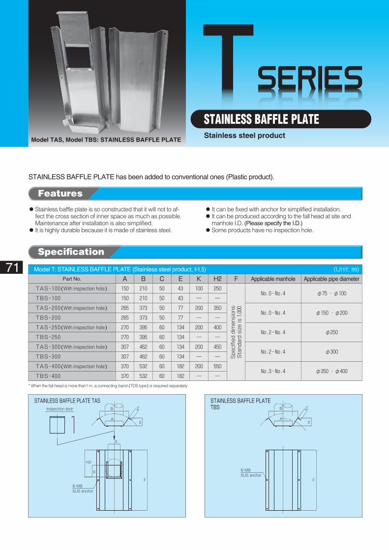
TSERIES
6-M8SUS anchor
Inspection door
STAINLESS BAFFLE PLATE TAS
EA
F
K
K
H2
B C
6-M8SUS anchor
EA
F
B C
STAINLESS BAFFLE PLATE TBS
71
Model TAS, Model TBS: STAINLESS BAFFLE PLATE
STAINLESS BAFFLE PLATEStainless steel product
STAINLESS BAFFLE PLATE has been added to conventional ones (Plastic product).
◦��Stainless baffle plate is so constructed that it will not to af-fect the cross section of inner space as much as possible. Maintenance after installation is also simplified.
◦��It is highly durable because it is made of stainless steel.
◦��It can be fixed with anchor for simplified installation.◦��It can be produced according to the fall head at site and
manhole I.D. (Please specify the I.D.)◦��Some products have no inspection hole.
Model T: STAINLESS BAFFLE PLATE (Stainless steel product, t-1.5)� (Unit: ㎜)Part No. A B C E K H2 F Applicable manhole Applicable pipe diameter
TAS-100(With inspection hole) 150 210 50 43 100 250
Spe
cifie
d dimen
sion
sSta
ndard size
is 1,00
0
No.0-No.4 φ75 ・ φ100TBS-100 150 210 50 43 ― ―
TAS-200(With inspection hole) 265 373 50 77 200 350No.0-No.4 φ150 ・ φ200
TBS-200 265 373 50 77 ― ―
TAS-250(With inspection hole) 270 395 60 134 200 400No.2-No.4 φ250
TBS-250 270 395 60 134 ― ―
TAS-300(With inspection hole) 307 462 60 134 200 450No.2-No.4 φ300
TBS-300 307 462 60 134 ― ―
TAS-400(With inspection hole) 370 532 60 182 200 550No.3-No.4 φ350 ・ φ400
TBS-400 370 532 60 182 ― ―
* When the fall head is more than1 m, a connecting band (TDS type) is required separately.
Features
Specification
72
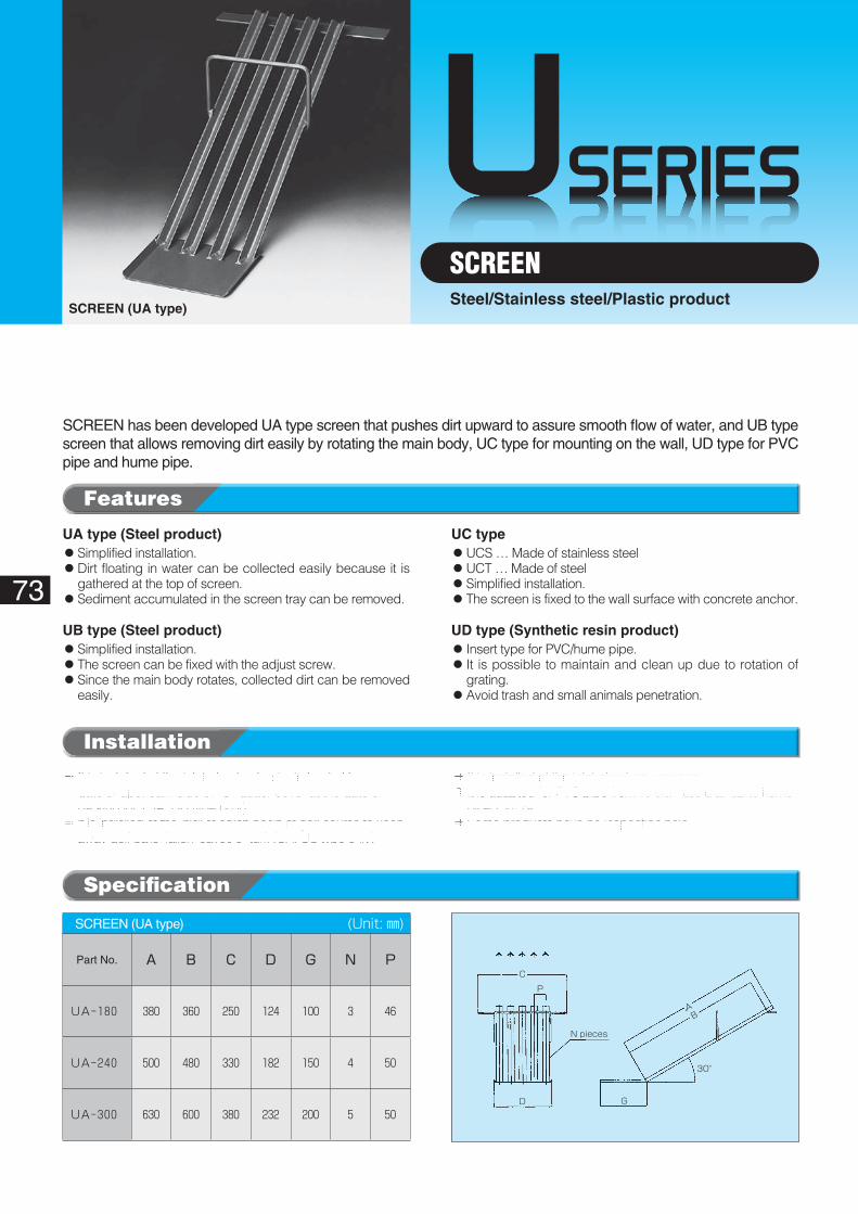
USERIES
D
P
C
N pieces
G
AB
30°
UA type (Steel product)◦��Simplified installation.◦��Dirt floating in water can be collected easily because it is
gathered at the top of screen.◦Sediment accumulated in the screen tray can be removed.
UB type (Steel product)◦��Simplified installation.◦��The screen can be fixed with the adjust screw.◦��Since the main body rotates, collected dirt can be removed
easily.
UC type◦��UCS … Made of stainless steel◦��UCT … Made of steel◦Simplified installation.◦��The screen is fixed to the wall surface with concrete anchor.
UD type (Synthetic resin product)◦��Insert type for PVC/hume pipe.◦��It is possible to maintain and clean up due to rotation of
grating.◦��Avoid trash and small animals penetration.
73
SCREEN (UA type)
SCREENSteel/Stainless steel/Plastic product
SCREEN has been developed UA type screen that pushes dirt upward to assure smooth flow of water, and UB type screen that allows removing dirt easily by rotating the main body, UC type for mounting on the wall, UD type for PVC pipe and hume pipe.
Installation
◦��It is installed at the inlet of catch basin, in front of house gate or upstream side of “U” gutter cover at the gate of parking lot. (UA, UB type only)
◦��It is installed at the inlet of catch basin at golf course to keep away golf balls, fallen leaves or turf. (UA, UB type only)
◦��It is installed at the inlet of culvert waterway.◦��It is adapted for PVC pipe from 75 dia ~250 dia, up to hume
pipe 250 dia.◦��Some products have no inspection hole.
SCREEN (UA type)� (Unit: ㎜)
Part No. A B C D G N P
UA-180 380 360 250 124 100 3 46
UA-240 500 480 330 182 150 4 50
UA-300 630 600 380 232 200 5 50
Features
Specification
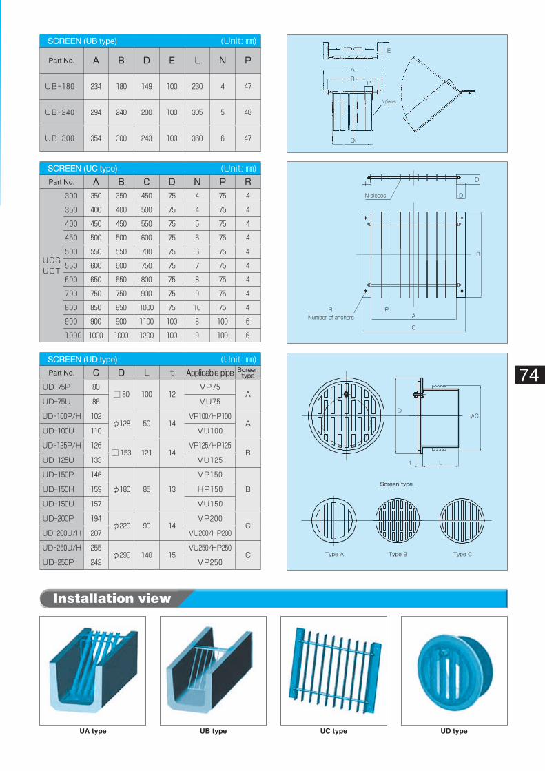
DφC
t L
Screen type
Type A Type B Type C
N pieces
D
D
B
A
C
PRNumber of anchors
D
P
N pieces
E
A
B
L
UA type UC typeUB type UD type
74
Installation view
SCREEN (UB type)� (Unit: ㎜)
Part No. A B D E L N P
UB-180 234 180 149 100 230 4 47
UB-240 294 240 200 100 305 5 48
UB-300 354 300 243 100 360 6 47
SCREEN (UC type)� (Unit: ㎜)Part No. A B C D N P R
UCSUCT
300 350 350 450 75 4 75 4
350 400 400 500 75 4 75 4
400 450 450 550 75 5 75 4
450 500 500 600 75 6 75 4
500 550 550 700 75 6 75 4
550 600 600 750 75 7 75 4
600 650 650 800 75 8 75 4
700 750 750 900 75 9 75 4
800 850 850 1000 75 10 75 4
900 900 900 1100 100 8 100 6
1000 1000 1000 1200 100 9 100 6
SCREEN (UD type)� (Unit: ㎜)Part No. C D L t Applicable�pipe Screen�
type
UD-75P 80□ 80 100 12
VP75A
UD-75U 86 VU75
UD-100P/H 102φ128 50 14
VP100/HP100A
UD-100U 110 VU100
UD-125P/H 126□ 153 121 14
VP125/HP125B
UD-125U 133 VU125
UD-150P 146
φ180 85 13
VP150
BUD-150H 159 HP150
UD-150U 157 VU150
UD-200P 194φ220 90 14
VP200C
UD-200U/H 207 VU200/HP200
UD-250U/H 255φ290 140 15
VU250/HP250C
UD-250P 242 VP250
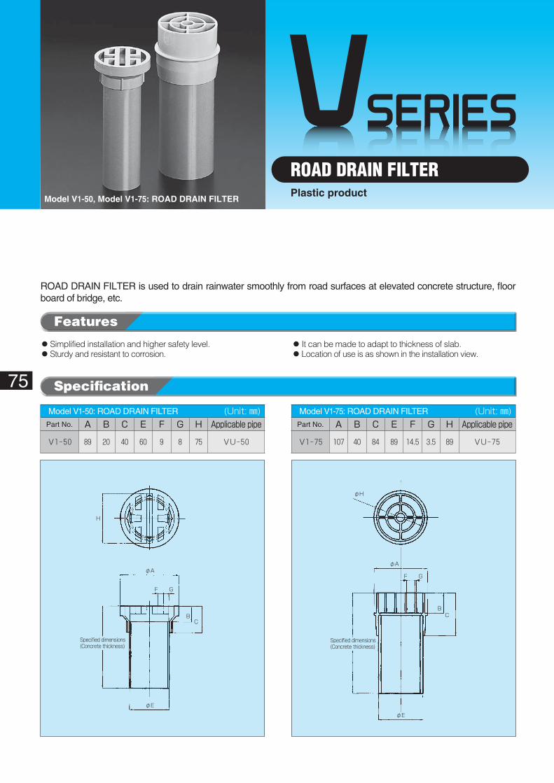
VSERIES
φA
F G
BC
φE
Specified dimensions(Concrete thickness)
φH
H
φA
F G
BC
φE
Specified dimensions(Concrete thickness)
75
Model V1-50, Model V1-75: ROAD DRAIN FILTER
ROAD DRAIN FILTERPlastic product
ROAD DRAIN FILTER is used to drain rainwater smoothly from road surfaces at elevated concrete structure, floor board of bridge, etc.
◦��Simplified installation and higher safety level.◦��Sturdy and resistant to corrosion.
◦��It can be made to adapt to thickness of slab.◦��Location of use is as shown in the installation view.
Model V1-50: ROAD DRAIN FILTER� (Unit: ㎜)Part No. A B C E F G H Applicable�pipe
V1-50 89 20 40 60 9 8 75 VU-50
Model V1-75: ROAD DRAIN FILTER� (Unit: ㎜)Part No. A B C E F G H Applicable�pipe
V1-75 107 40 84 89 14.5 3.5 89 VU-75
Features
Specification
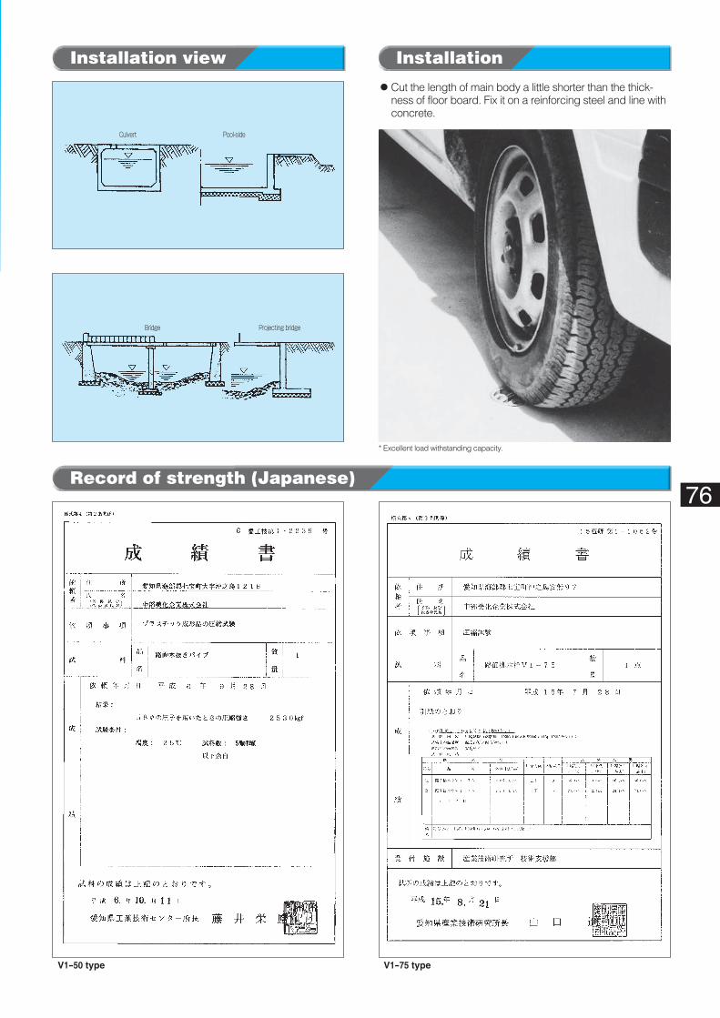
Culvert Pool-side
Bridge Projecting bridge
76
Installation view Installation
Record of strength (Japanese)
V1-50 type V1-75 type
◦��Cut the length of main body a little shorter than the thick-ness of floor board. Fix it on a reinforcing steel and line with concrete.
* Excellent load withstanding capacity.
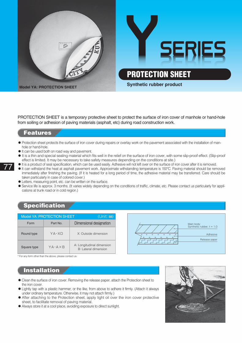
YSERIES
Main body: Synthetic rubber, t = 1.0
Adhesive
Release paper
77
Model YA: PROTECTION SHEET
PROTECTION SHEETSynthetic rubber product
PROTECTION SHEET is a temporary protective sheet to protect the surface of iron cover of manhole or hand-hole from soiling or adhesion of paving materials (asphalt, etc) during road construction work.
◦ Protection sheet protects the surface of iron cover during repairs or overlay work on the pavement associated with the installation of man-hole or hand-hole.
◦ It can be used both on road way and pavement.◦ It is a thin and special sealing material which fits well in the relief on the surface of iron cover, with some slip-proof effect. (Slip-proof
effect is limited. It may be necessary to take safety measures depending on the conditions at site.)◦ It is a product of seal specification, which can be used easily. Adhesive will not left over on the surface of iron cover after it is removed.◦��It can withstand the heat at asphalt pavement work. Approximate withstanding temperature is 150°C. Paving material should be removed
immediately after finishing the paving. (If it is heated for a long period of time, the adhesive material may be transferred. Care should be taken particularly in case of colored cover.)
◦��Letters, measuring point, etc. can be written on the surface.◦��Service life is approx. 3 months. (It varies widely depending on the conditions of traffic, climate, etc. Please contact us particularly for appli-
cations at trunk road or in cold region.)
◦��Clean the surface of iron cover. Removing the release paper, attach the Protection sheet to the iron cover.
◦��Lightly tap with a plastic hammer, or the like, from above to adhere it firmly. (Attach it always under ordinary temperature. Otherwise, it may not attach firmly.)
◦ After attaching to the Protection sheet, apply light oil over the iron cover protective sheet, to facilitate removal of paving material.
◦Always store it at a cool place, avoiding exposure to direct sunlight.
Installation
Model YA: PROTECTION SHEET� (Unit: ㎜)Form Part No. Dimensional�designation
Round type YA-XD X: Outside dimension
Square type YA-A×B A: Longitudinal dimensionB: Lateral dimension
* For any form other than the above, please contact us.
Features
Specification
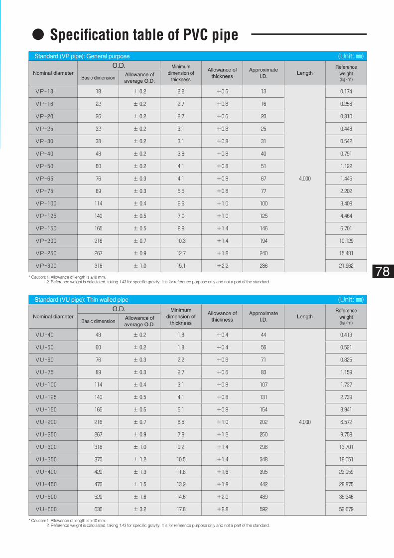
78
◦Specification table of PVC pipeStandard (VP pipe): General purpose� (Unit: ㎜)
Nominal diameterO.D. Minimum
dimension of thickness
Allowance of thickness
Approximate I.D.
LengthReference
weight(㎏/m)Basic dimension
Allowance of average O.D.
VP-13 18 ± 0.2 2.2 +0.6 13
4,000
0.174
VP-16 22 ± 0.2 2.7 +0.6 16 0.256
VP-20 26 ± 0.2 2.7 +0.6 20 0.310
VP-25 32 ± 0.2 3.1 +0.8 25 0.448
VP-30 38 ± 0.2 3.1 +0.8 31 0.542
VP-40 48 ± 0.2 3.6 +0.8 40 0.791
VP-50 60 ± 0.2 4.1 +0.8 51 1.122
VP-65 76 ± 0.3 4.1 +0.8 67 1.445
VP-75 89 ± 0.3 5.5 +0.8 77 2.202
VP-100 114 ± 0.4 6.6 +1.0 100 3.409
VP-125 140 ± 0.5 7.0 +1.0 125 4.464
VP-150 165 ± 0.5 8.9 +1.4 146 6.701
VP-200 216 ± 0.7 10.3 +1.4 194 10.129
VP-250 267 ± 0.9 12.7 +1.8 240 15.481
VP-300 318 ± 1.0 15.1 +2.2 286 21.962
Standard (VU pipe): Thin walled pipe� (Unit: ㎜)
Nominal diameterO.D. Minimum
dimension of thickness
Allowance of thickness
Approximate I.D.
LengthReference
weight(㎏/m)Basic dimension
Allowance of average O.D.
VU-40 48 ± 0.2 1.8 +0.4 44
4,000
0.413
VU-50 60 ± 0.2 1.8 +0.4 56 0.521
VU-60 76 ± 0.3 2.2 +0.6 71 0.825
VU-75 89 ± 0.3 2.7 +0.6 83 1.159
VU-100 114 ± 0.4 3.1 +0.8 107 1.737
VU-125 140 ± 0.5 4.1 +0.8 131 2.739
VU-150 165 ± 0.5 5.1 +0.8 154 3.941
VU-200 216 ± 0.7 6.5 +1.0 202 6.572
VU-250 267 ± 0.9 7.8 +1.2 250 9.758
VU-300 318 ± 1.0 9.2 +1.4 298 13.701
VU-350 370 ± 1.2 10.5 +1.4 348 18.051
VU-400 420 ± 1.3 11.8 +1.6 395 23.059
VU-450 470 ± 1.5 13.2 +1.8 442 28.875
VU-500 520 ± 1.6 14.6 +2.0 489 35.346
VU-600 630 ± 3.2 17.8 +2.8 592 52.679
* Caution: 1. Allowance of length is ±10 mm.2. Reference weight is calculated, taking 1.43 for specific gravity. It is for reference purpose only and not a part of the standard.
* Caution: 1. Allowance of length is ±10 mm.2. Reference weight is calculated, taking 1.43 for specific gravity. It is for reference purpose only and not a part of the standard.

WE CONTEMPLATE FLOW PHENOMENA! WE EXPLORE MYSTERY OF SOIL!
CHUBUBIKA CORPORATIONHead office : 97,Annaku,Shippo-cho Okinoshima,Ama,
Aichi 497‐0001,JAPANURL : http://www.chububika.co.jpE-mail : [email protected]