Fm Spas120c en Dca
50
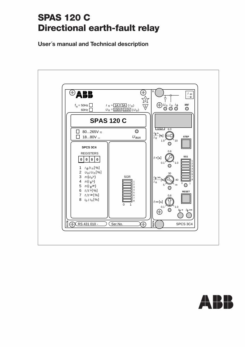
SPAS 120 C Directional earth-fault relay User´s manual and Technical description RS 431 010 - Ser.No. SPAS 120 C 2 5 0117B f n = 50Hz 60Hz 1 2 3 4 5 6 7 8 / > t t % [ ] >> / t t % [ ] U aux 80...265V ~ – 18...80V – SPCS 3C4 REGISTERS 0 0 0 0 1 2 3 4 5 6 7 8 0 1 SGR n ( ) > I ϕ n ( ) >> I ϕ I n / I ϕ % [ ] n ( ) U o % [ ] / n U U o n I = n U = 100V ( ) o I ( ) U o 110V 1A 5A > o IRF 0047A 0.6 0.1 1.0 30 5 0.6 0.1 1.0 1.0 6.0 10 STEP RESET SG1 0 1 1 2 3 4 5 6 7 8 40 SPCS 3C4 B I >> I ϕ > I ϕ [ ] s > t n I n I >> t [ ] s > I ϕ >> I ϕ [ ] % [ ] % U o I ϕ I STEP % [ ] / n I I o
description
spas 120c relay manual
Transcript of Fm Spas120c en Dca
SPAS 120 CDirectional earth-fault relay
User´s manual and Technical description
RS 431 010 - Ser.No.
SPAS 120 C
2
5
0117
B
fn = 50Hz
60Hz
12345678
/ >tt %[ ]>>/ tt %[ ]
Uaux
80...265V ~–
18...80V –
SPCS 3C4
REGISTERS
0 0 0 0
12345678
0 1
SGR
n ( )>I ϕn ( )>>I ϕ
I n/Iϕ %[ ]
n ( )Uo
%[ ]/ nU Uo
nI =
nU = 100V
( )oI( )U o110V
1A 5A
>
o IRF
0047
A0.6
0.1 1.0
30
5
0.6
0.1 1.0
1.0
6.0
10
STEP
RESET
SG1
0 1
1234567840
SPCS 3C4
BI
>>Iϕ>Iϕ
[ ]s>t
nI
nI
>>t [ ]s
>I ϕ
>>I ϕ [ ]%
[ ]%
U oI ϕI
STEP
%[ ]/ nI Io
2
1MRS 750639-MUM EN
Issued 1997-02-06Modified 2002-04-25Version D (replaces 34 SPAS 4 EN1)Checked MKApproved OL
Data subject to change without notice
SPAS 120 CDirectional
earth-fault relay
Contents Features .......................................................................................................................... 2Application ..................................................................................................................... 3Description of operation ................................................................................................. 3Connections ................................................................................................................... 4Configuration of output relays ........................................................................................ 6Start and operation indicators ......................................................................................... 7Power supply and I/O module ........................................................................................ 7Technical data (modified 2002-04) ................................................................................. 8Examples of application ................................................................................................ 10Recorded data and fault analysis (modified 2000-02) .................................................... 16Secondary injection testing ........................................................................................... 17Maintenance and repair ................................................................................................ 21Exchange and spare parts .............................................................................................. 21Ordering numbers ........................................................................................................ 21Dimensions and mounting ........................................................................................... 22Order information ........................................................................................................ 22
The complete manual for the directional earth-fault relay SPAS 120 C includesthe following submanuals:
Directional earth-fault relay module SPCS 3C4 1MRS 750350-MUM ENGeneral characteristics of C type relay modules 1MRS 750328-MUM EN
Features Two-stage directional earth-fault relay for dis-tribution networks
Directional low-set earth-fault stage with defi-nite time characteristic
Directional high-set earth-fault stage with in-stantaneous operation or definite time charac-teristic
The operation direction of the high-set earth-fault stage can be the same as that of the low-setstage or the opposite
Output relay functions can be freely configuredby the user
Flexible adaptation of the relay to differentapplications
Manual selection or remote control of the op-eration characteristic I0sinϕ or I0cosϕ
Digital display of settings, measured quantities,recorded fault values, etc
Extensive two-way data communication via fi-bre-optic serial bus
Continuous self-supervision of hardware andsoftware including autodiagnosis
Powerful software support for parametrizationand supervision of the relay
Member of the SPACOM product family andPYRAMID®, ABB's coordinated protection andcontrol concept
3
Application The directional earth-fault relay SPAS 120 C isdesigned to be used for selective feeder earth-fault protection in isolated neutral and impe-dance earthed networks. The relay is especiallyuseful in networks, where the operation charac-teristic of the earth-fault relay must be remotelycontrollable.
The directional earth-fault relay can also be usedfor the earth-fault protection of power genera-tors and large motors.
The relay is a member of the SPACOM productfamily, which is part of PYRAMID®, ABB'scoordinated protection and control concept.
Description offunction
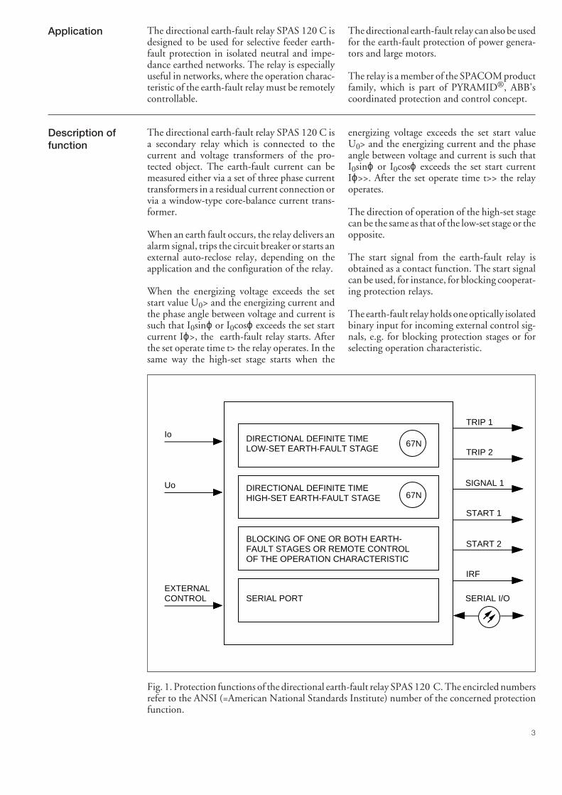
The directional earth-fault relay SPAS 120 C isa secondary relay which is connected to thecurrent and voltage transformers of the pro-tected object. The earth-fault current can bemeasured either via a set of three phase currenttransformers in a residual current connection orvia a window-type core-balance current trans-former.
When an earth fault occurs, the relay delivers analarm signal, trips the circuit breaker or starts anexternal auto-reclose relay, depending on theapplication and the configuration of the relay.
When the energizing voltage exceeds the setstart value U0> and the energizing current andthe phase angle between voltage and current issuch that I0sinϕ or I0cosϕ exceeds the set startcurrent Iϕ>, the earth-fault relay starts. Afterthe set operate time t> the relay operates. In thesame way the high-set stage starts when the
energizing voltage exceeds the set start valueU0> and the energizing current and the phaseangle between voltage and current is such thatI0sinϕ or I0cosϕ exceeds the set start currentIϕ>>. After the set operate time t>> the relayoperates.
The direction of operation of the high-set stagecan be the same as that of the low-set stage or theopposite.
The start signal from the earth-fault relay isobtained as a contact function. The start signalcan be used, for instance, for blocking cooperat-ing protection relays.
The earth-fault relay holds one optically isolatedbinary input for incoming external control sig-nals, e.g. for blocking protection stages or forselecting operation characteristic.
DIRECTIONAL DEFINITE TIMELOW-SET EARTH-FAULT STAGE
DIRECTIONAL DEFINITE TIMEHIGH-SET EARTH-FAULT STAGE
BLOCKING OF ONE OR BOTH EARTH-FAULT STAGES OR REMOTE CONTROL OF THE OPERATION CHARACTERISTIC
SERIAL PORT
67N
67N
TRIP 1
TRIP 2
START 1
IRF
SIGNAL 1
SERIAL I/O
Io
EXTERNALCONTROL
START 2
Uo
Fig. 1. Protection functions of the directional earth-fault relay SPAS 120 C. The encircled numbersrefer to the ANSI (=American National Standards Institute) number of the concerned protectionfunction.
4
Connections
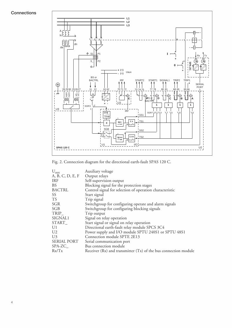
Fig. 2. Connection diagram for the directional earth-fault SPAS 120 C.
Uaux Auxiliary voltageA, B, C, D, E, F Output relaysIRF Self-supervision outputBS Blocking signal for the protection stagesBACTRL Control signal for selection of operation characteristicSS Start signalTS Trip signalSGR Switchgroup for configuring operate and alarm signalsSGB Switchgroup for configuring blocking signalsTRIP_ Trip outputSIGNAL1 Signal on relay operationSTART_ Start signal or signal on relay operationU1 Directional earth-fault relay module SPCS 3C4U2 Power supply and I/O module SPTU 240S1 or SPTU 48S1U3 Connection module SPTE 2E13SERIAL PORT Serial communication portSPA-ZC_ Bus connection moduleRx/Tx Receiver (Rx) and transmitter (Tx) of the bus connection module
SPAS 120 C
0
I
0
I
U2
U3
U3
-
-
+
1 1 1
C B A
+
1
D
+
+ -
Uaux
E
+-
(~)(~)
100V110V
L1L2L3
A
N
dadn
5A1A
P1
P2
S1
S_
65 66696881807877727170
SGR 3 2 4 7 5 8 6
SPA
-ZC
_
Rx Tx
621211272625302928 61
~
START1 SIGNAL1 TRIP2 TRIP1START2IRF
IRF
74 7573
F
TS2
TS1
SS1
SS2
U1 I/O
t >>
t >Iϕ>
Iϕ>>
SERIALPORT
SGR/1
SGB
5
4
sinϕcosϕ
0
1
BS orBACTRL
BS orBACTRL
5
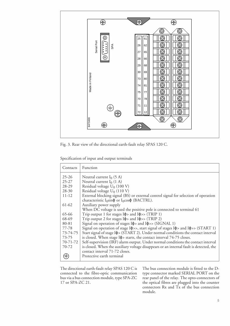
Fig. 3. Rear view of the directional earth-fault relay SPAS 120 C.
Specification of input and output terminals
Contacts Function
25-26 Neutral current I0 (5 A)25-27 Neutral current I0 (1 A)28-29 Residual voltage U0 (100 V)28-30 Residual voltage U0 (110 V)11-12 External blocking signal (BS) or external control signal for selection of operation
characteristic I0sinϕ or I0cosϕ (BACTRL).61-62 Auxiliary power supply
When DC voltage is used the positive pole is connected to terminal 6165-66 Trip output 1 for stages Iϕ> and Iϕ>> (TRIP 1)68-69 Trip output 2 for stages Iϕ> and Iϕ>> (TRIP 2)80-81 Signal on operation of stages Iϕ> and Iϕ>> (SIGNAL 1)77-78 Signal on operation of stage Iϕ>>, start signal of stages Iϕ> and Iϕ>> (START 1)73-74-75 Start signal of stage Iϕ> (START 2). Under normal conditions the contact interval73-75 is closed. When stage Iϕ> starts, the contact interval 74-75 closes.70-71-72 Self-supervision (IRF) alarm output. Under normal conditions the contact interval70-72 is closed. When the auxiliary voltage disappears or an internal fault is detected, the
contact interval 71-72 closes.Protective earth terminal
The directional earth-fault relay SPAS 120 C isconnected to the fibre-optic communicationbus via a bus connection module, type SPA-ZC17 or SPA-ZC 21.
The bus connection module is fitted to the D-type connector marked SERIAL PORT on therear panel of the relay. The opto-connectors ofthe optical fibres are plugged into the counterconnectors Rx and Tx of the bus connectionmodule.
Mad
e in
Fin
land
25
26
27
28
29
30
73
74
75
70
71
72
61
62
65
66
68
69
80
81
77
78
11
12
B47
0499
Ser
ial P
ort
SP
A
6
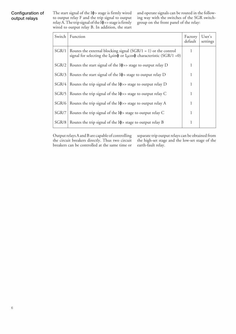
and operate signals can be routed in the follow-ing way with the switches of the SGR switch-group on the front panel of the relay:
Switch Function Factory User'sdefault settings
SGR/1 Routes the external blocking signal (SGR/1 = 1) or the control 1signal for selecting the I0sinϕ or I0cosϕ characteristic (SGR/1 =0)
SGR/2 Routes the start signal of the Iϕ>> stage to output relay D 1
SGR/3 Routes the start signal of the Iϕ> stage to output relay D 1
SGR/4 Routes the trip signal of the Iϕ>> stage to output relay D 1
SGR/5 Routes the trip signal of the Iϕ>> stage to output relay C 1
SGR/6 Routes the trip signal of the Iϕ>> stage to output relay A 1
SGR/7 Routes the trip signal of the Iϕ> stage to output relay C 1
SGR/8 Routes the trip signal of the Iϕ> stage to output relay B 1
Configuration ofoutput relays
The start signal of the Iϕ> stage is firmly wiredto output relay F and the trip signal to outputrelay A. The trip signal of the Iϕ>> stage is firmlywired to output relay B. In addition, the start
Output relays A and B are capable of controllingthe circuit breakers directly. Thus two circuitbreakers can be controlled at the same time or
separate trip output relays can be obtained fromthe high-set stage and the low-set stage of theearth-fault relay.
7
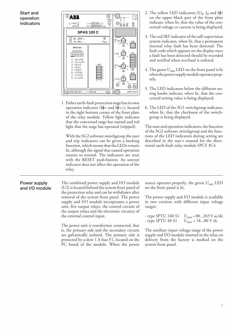
Start andoperationindicators
2. The yellow LED indicators (U0, I0 and Iϕ)on the upper black part of the front plateindicate, when lit, that the value of the con-cerned voltage or current is being displayed.
3. The red IRF indicator of the self-supervisionsystem indicates, when lit, that a permanentinternal relay fault has been detected. Thefault code which appears on the display oncea fault has been detected should be recordedand notified when overhaul is ordered.
4. The green Uaux LED on the front panel is litwhen the power supply module operates prop-erly.
5. The LED indicators below the different set-ting knobs indicate, when lit, that the con-cerned setting value is being displayed.
6. The LED of the SG1 switchgroup indicates,when lit, that the checksum of the switch-group is being displayed.
The start and operation indicators, the functionof the SG2 software switchgroup and the func-tions of the LED indicators during setting aredescribed in the user's manual for the direc-tional earth-fault relay module SPCS 3C4.
1. Either earth-fault protection stage has its ownoperation indicator (Iϕ> and Iϕ>>), locatedin the right bottom corner of the front plateof the relay module. Yellow light indicatesthat the concerned stage has started and redlight that the stage has operated (tripped).
With the SG2 software switchgroup the startand trip indicators can be given a latchingfunction, which means that the LEDs remainlit, although the signal that caused operationreturns to normal. The indicators are resetwith the RESET push-button. An unresetindicator does not affect the operation of therelay.
The combined power supply and I/O module(U2) is located behind the system front panel ofthe protection relay and can be withdrawn afterremoval of the system front panel. The powersupply and I/O module incorporates a powerunit, five output relays, the control circuits ofthe output relays and the electronic circuitry ofthe external control input.
The power unit is transformer connected, thatis, the primary side and the secondary circuitsare galvanically isolated. The primary side isprotected by a slow 1 A fuse F1, located on thePC board of the module. When the power
source operates properly, the green Uaux LEDon the front panel is lit.
The power supply and I/O module is availablein two versions with different input voltageranges:
- type SPTU 240 S1 Uaux = 80...265 V ac/dc- type SPTU 48 S1 Uaux = 18...80 V dc
The auxiliary input voltage range of the powersupply and I/O module inserted in the relay ondelivery from the factory is marked on thesystem front panel.
Power supplyand I/O module
RS 431 010 - Ser.No.
SPAS 120 C
2
5
0117
B
fn = 50Hz
60Hz
12345678
/ >tt %[ ]>>/ tt %[ ]
Uaux
80...265V ~–
18...80V –
SPCS 3C4
REGISTERS
0 0 0 0
12345678
0 1
SGR
n ( )>I ϕn ( )>>I ϕ
I n/Iϕ %[ ]
n ( )Uo
%[ ]/ nU Uo
nI =
nU = 100V
( )oI( )U o110V
1A 5A
>
o IRF
0047
A
0.6
0.1 1.0
30
5
0.6
0.1 1.0
1.0
6.0
10
STEP
RESET
SG1
0 1
1234567840
SPCS 3C4
BI
>>Iϕ>Iϕ
[ ]s>t
nI
nI
>>t [ ]s
>I ϕ
>>I ϕ [ ]%
[ ]%
U oI ϕI
STEP
%[ ]/ nI Io
8
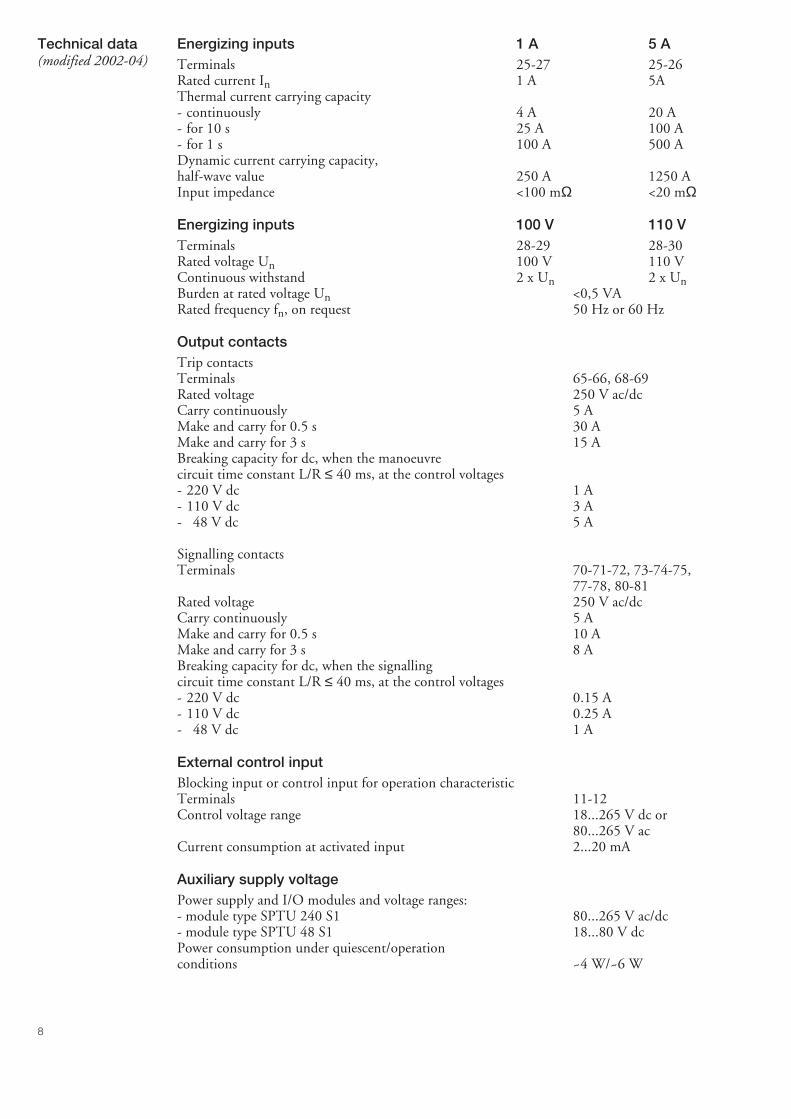
Energizing inputs 1 A 5 ATerminals 25-27 25-26Rated current In 1 A 5AThermal current carrying capacity- continuously 4 A 20 A- for 10 s 25 A 100 A- for 1 s 100 A 500 ADynamic current carrying capacity,half-wave value 250 A 1250 AInput impedance <100 mΩ <20 mΩ
Energizing inputs 100 V 110 VTerminals 28-29 28-30Rated voltage Un 100 V 110 VContinuous withstand 2 x Un 2 x UnBurden at rated voltage Un <0,5 VARated frequency fn, on request 50 Hz or 60 Hz
Output contactsTrip contactsTerminals 65-66, 68-69Rated voltage 250 V ac/dcCarry continuously 5 AMake and carry for 0.5 s 30 AMake and carry for 3 s 15 ABreaking capacity for dc, when the manoeuvrecircuit time constant L/R ≤ 40 ms, at the control voltages- 220 V dc 1 A- 110 V dc 3 A- 48 V dc 5 A
Signalling contactsTerminals 70-71-72, 73-74-75,
77-78, 80-81Rated voltage 250 V ac/dcCarry continuously 5 AMake and carry for 0.5 s 10 AMake and carry for 3 s 8 ABreaking capacity for dc, when the signallingcircuit time constant L/R ≤ 40 ms, at the control voltages- 220 V dc 0.15 A- 110 V dc 0.25 A- 48 V dc 1 A
External control inputBlocking input or control input for operation characteristicTerminals 11-12Control voltage range 18...265 V dc or
80...265 V acCurrent consumption at activated input 2...20 mA
Auxiliary supply voltagePower supply and I/O modules and voltage ranges:- module type SPTU 240 S1 80...265 V ac/dc- module type SPTU 48 S1 18...80 V dcPower consumption under quiescent/operationconditions ~4 W/~6 W
Technical data(modified 2002-04)
9
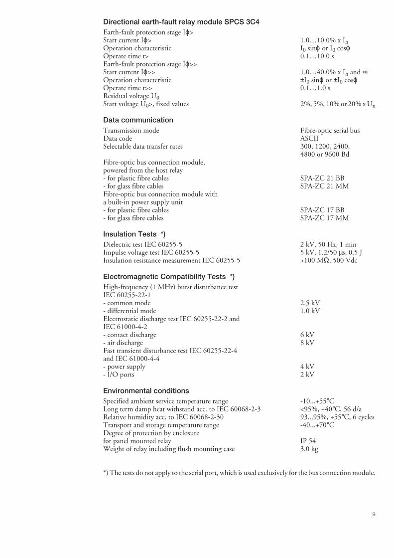
Directional earth-fault relay module SPCS 3C4Earth-fault protection stage Iϕ>Start current Iϕ> 1.0…10.0% x InOperation characteristic I0 sinϕ or I0 cosϕOperate time t> 0.1…10.0 sEarth-fault protection stage Iϕ>>Start current Iϕ>> 1.0…40.0% x In and ∞Operation characteristic ±I0 sinϕ or ±I0 cosϕOperate time t>> 0.1…1.0 sResidual voltage U0Start voltage U0>, fixed values 2%, 5%, 10% or 20% x Un
Data communicationTransmission mode Fibre-optic serial busData code ASCIISelectable data transfer rates 300, 1200, 2400,
4800 or 9600 BdFibre-optic bus connection module,powered from the host relay- for plastic fibre cables SPA-ZC 21 BB- for glass fibre cables SPA-ZC 21 MMFibre-optic bus connection module witha built-in power supply unit- for plastic fibre cables SPA-ZC 17 BB- for glass fibre cables SPA-ZC 17 MM
Insulation Tests *)Dielectric test IEC 60255-5 2 kV, 50 Hz, 1 minImpulse voltage test IEC 60255-5 5 kV, 1.2/50 µs, 0.5 JInsulation resistance measurement IEC 60255-5 >100 MΩ, 500 Vdc
Electromagnetic Compatibility Tests *)High-frequency (1 MHz) burst disturbance testIEC 60255-22-1- common mode 2.5 kV- differential mode 1.0 kVElectrostatic discharge test IEC 60255-22-2 andIEC 61000-4-2- contact discharge 6 kV- air discharge 8 kVFast transient disturbance test IEC 60255-22-4and IEC 61000-4-4- power supply 4 kV- I/O ports 2 kV
Environmental conditionsSpecified ambient service temperature range -10...+55°CLong term damp heat withstand acc. to IEC 60068-2-3 <95%, +40°C, 56 d/aRelative humidity acc. to IEC 60068-2-30 93...95%, +55°C, 6 cyclesTransport and storage temperature range -40...+70°CDegree of protection by enclosurefor panel mounted relay IP 54Weight of relay including flush mounting case 3.0 kg
*) The tests do not apply to the serial port, which is used exclusively for the bus connection module.
10
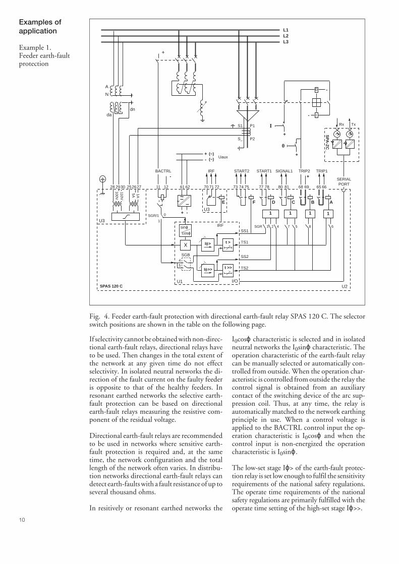
Fig. 4. Feeder earth-fault protection with directional earth-fault relay SPAS 120 C. The selectorswitch positions are shown in the table on the following page.
Examples ofapplication
Example 1.Feeder earth-faultprotection
If selectivity cannot be obtained with non-direc-tional earth-fault relays, directional relays haveto be used. Then changes in the total extent ofthe network at any given time do not effectselectivity. In isolated neutral networks the di-rection of the fault current on the faulty feederis opposite to that of the healthy feeders. Inresonant earthed networks the selective earth-fault protection can be based on directionalearth-fault relays measuring the resistive com-ponent of the residual voltage.
Directional earth-fault relays are recommendedto be used in networks where sensitive earth-fault protection is required and, at the sametime, the network configuration and the totallength of the network often varies. In distribu-tion networks directional earth-fault relays candetect earth-faults with a fault resistance of up toseveral thousand ohms.
In resitively or resonant earthed networks the
I0cosϕ characteristic is selected and in isolatedneutral networks the I0sinϕ characteristic. Theoperation characteristic of the earth-fault relaycan be manually selected or automatically con-trolled from outside. When the operation char-acteristic is controlled from outside the relay thecontrol signal is obtained from an auxiliarycontact of the switching device of the arc sup-pression coil. Thus, at any time, the relay isautomatically matched to the network earthingprinciple in use. When a control voltage isapplied to the BACTRL control input the op-eration characteristic is I0cosϕ and when thecontrol input is non-energized the operationcharacteristic is I0sinϕ.
The low-set stage Iϕ> of the earth-fault protec-tion relay is set low enough to fulfil the sensitivityrequirements of the national safety regulations.The operate time requirements of the nationalsafety regulations are primarily fulfilled with theoperate time setting of the high-set stage Iϕ>>.
SPAS 120 C
0
I
0
I
U2
U3
U3
-
-
+
1 1 1
C B A
+
1
D
+
+ -
Uaux
E
+-
(~)(~)
100V110V
L1L2L3
5A 1A
P1
P2
S1
S_
65 66696881807877727170
SGR 3 2 4 7 5 8 6
SP
A-Z
C_
Rx Tx
621211272625302928 61
~
START1 SIGNAL1 TRIP2 TRIP1START2
SGR/1
IRF
IRF
74 7573
F
TS2
TS1
SGB
SS1
SS2
U1
54
I/O
t >>
t >Iϕ>
Iϕ>>
sinϕcosϕ
0
1
-BACTRL
+
A
N
dadn
SERIALPORT
11
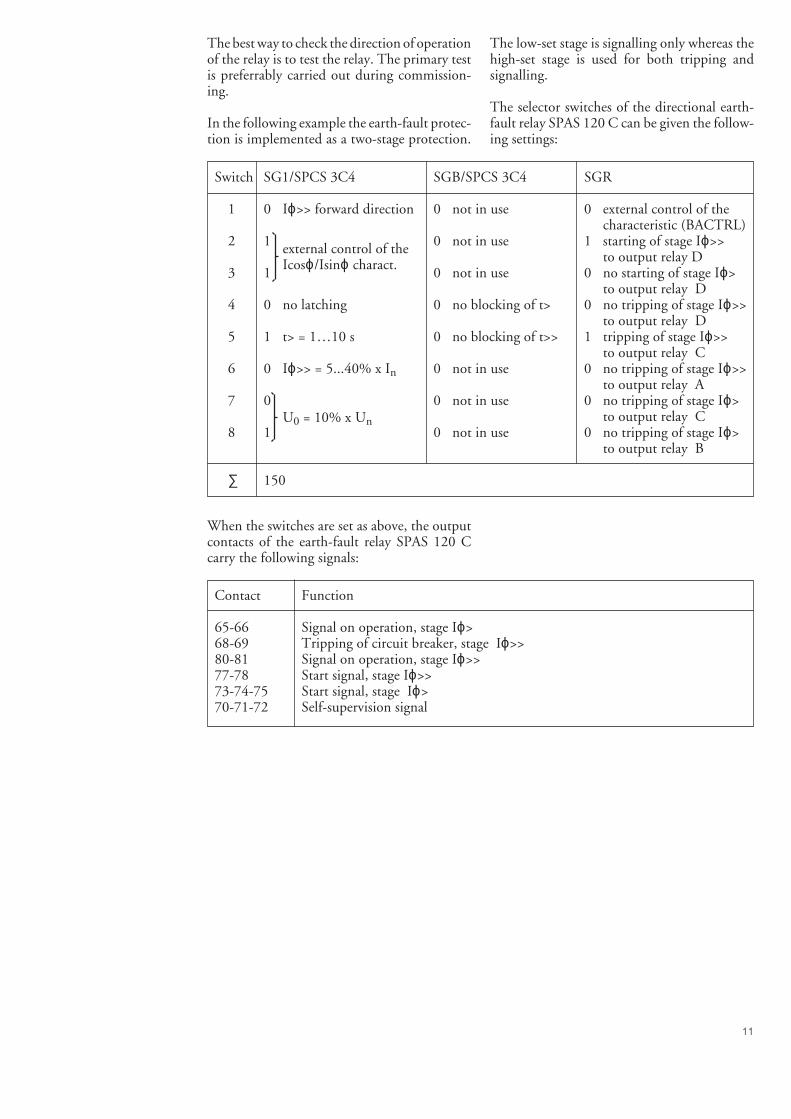
The best way to check the direction of operationof the relay is to test the relay. The primary testis preferrably carried out during commission-ing.
In the following example the earth-fault protec-tion is implemented as a two-stage protection.
The low-set stage is signalling only whereas thehigh-set stage is used for both tripping andsignalling.
The selector switches of the directional earth-fault relay SPAS 120 C can be given the follow-ing settings:
Switch SG1/SPCS 3C4 SGB/SPCS 3C4 SGR
1 0 Iϕ>> forward direction 0 not in use 0 external control of thecharacteristic (BACTRL)
2 1 0 not in use 1 starting of stage Iϕ>>to output relay D
3 1 0 not in use 0 no starting of stage Iϕ>to output relay D
4 0 no latching 0 no blocking of t> 0 no tripping of stage Iϕ>>to output relay D
5 1 t> = 1…10 s 0 no blocking of t>> 1 tripping of stage Iϕ>>to output relay C
6 0 Iϕ>> = 5...40% x In 0 not in use 0 no tripping of stage Iϕ>>to output relay A
7 0 0 not in use 0 no tripping of stage Iϕ>to output relay C
8 1 0 not in use 0 no tripping of stage Iϕ>to output relay B
∑ 150
external control of theIcosϕ/Isinϕ charact.
U0 = 10% x Un
When the switches are set as above, the outputcontacts of the earth-fault relay SPAS 120 Ccarry the following signals:
Contact Function
65-66 Signal on operation, stage Iϕ>68-69 Tripping of circuit breaker, stage Iϕ>>80-81 Signal on operation, stage Iϕ>>77-78 Start signal, stage Iϕ>>73-74-75 Start signal, stage Iϕ>70-71-72 Self-supervision signal
12
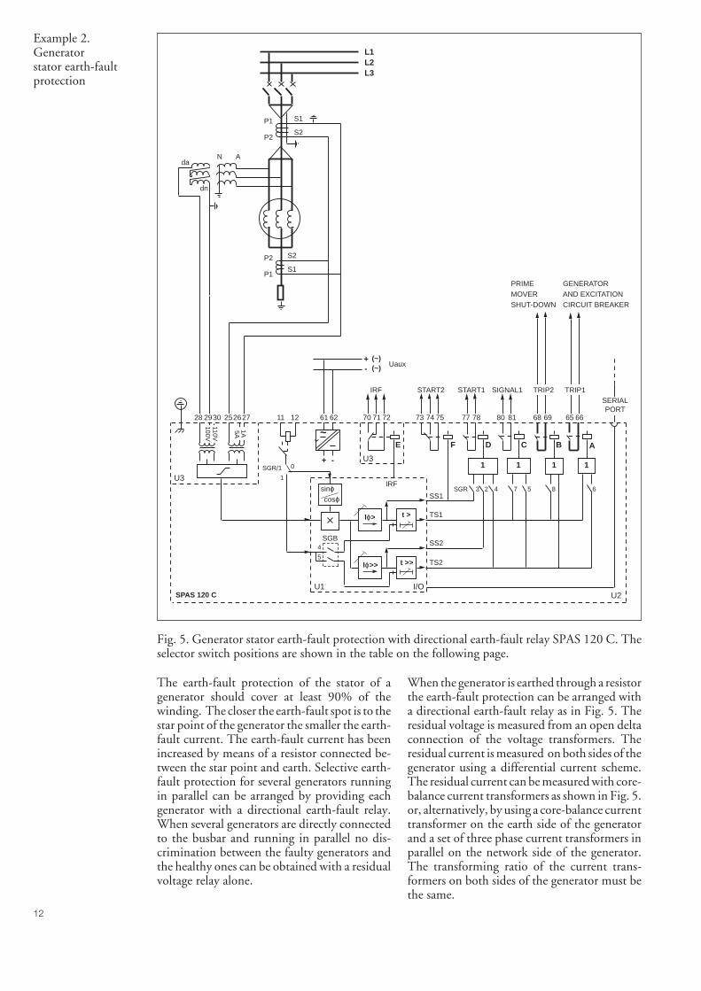
Example 2.Generatorstator earth-faultprotection
Fig. 5. Generator stator earth-fault protection with directional earth-fault relay SPAS 120 C. Theselector switch positions are shown in the table on the following page.
The earth-fault protection of the stator of agenerator should cover at least 90% of thewinding. The closer the earth-fault spot is to thestar point of the generator the smaller the earth-fault current. The earth-fault current has beenincreased by means of a resistor connected be-tween the star point and earth. Selective earth-fault protection for several generators runningin parallel can be arranged by providing eachgenerator with a directional earth-fault relay.When several generators are directly connectedto the busbar and running in parallel no dis-crimination between the faulty generators andthe healthy ones can be obtained with a residualvoltage relay alone.
When the generator is earthed through a resistorthe earth-fault protection can be arranged witha directional earth-fault relay as in Fig. 5. Theresidual voltage is measured from an open deltaconnection of the voltage transformers. Theresidual current is measured on both sides of thegenerator using a differential current scheme.The residual current can be measured with core-balance current transformers as shown in Fig. 5.or, alternatively, by using a core-balance currenttransformer on the earth side of the generatorand a set of three phase current transformers inparallel on the network side of the generator.The transforming ratio of the current trans-formers on both sides of the generator must bethe same.
SPAS 120 C U2
U3
U31 1 1
C B A
1
D
+ -
Uaux
E
+-
(~)(~)
100V110V
5A1A
65 66696881807877727170
SGR 3 2 4 7 5 8 6
621211272625302928 61
~
START1 SIGNAL1 TRIP2 TRIP1START2IRF
IRF
74 7573
F
TS2
TS1
SS1
SS2
U1 I/O
t >>
t >Iϕ>
Iϕ>>
L1L2L3
SERIALPORT
SGR/1
SGB
5
4
sinϕcosϕ
0
1
P1
P2
S1
S2
P1
P2
S1
S2
ANda
dn
PRIMEMOVERSHUT-DOWN
GENERATORAND EXCITATIONCIRCUIT BREAKER
13
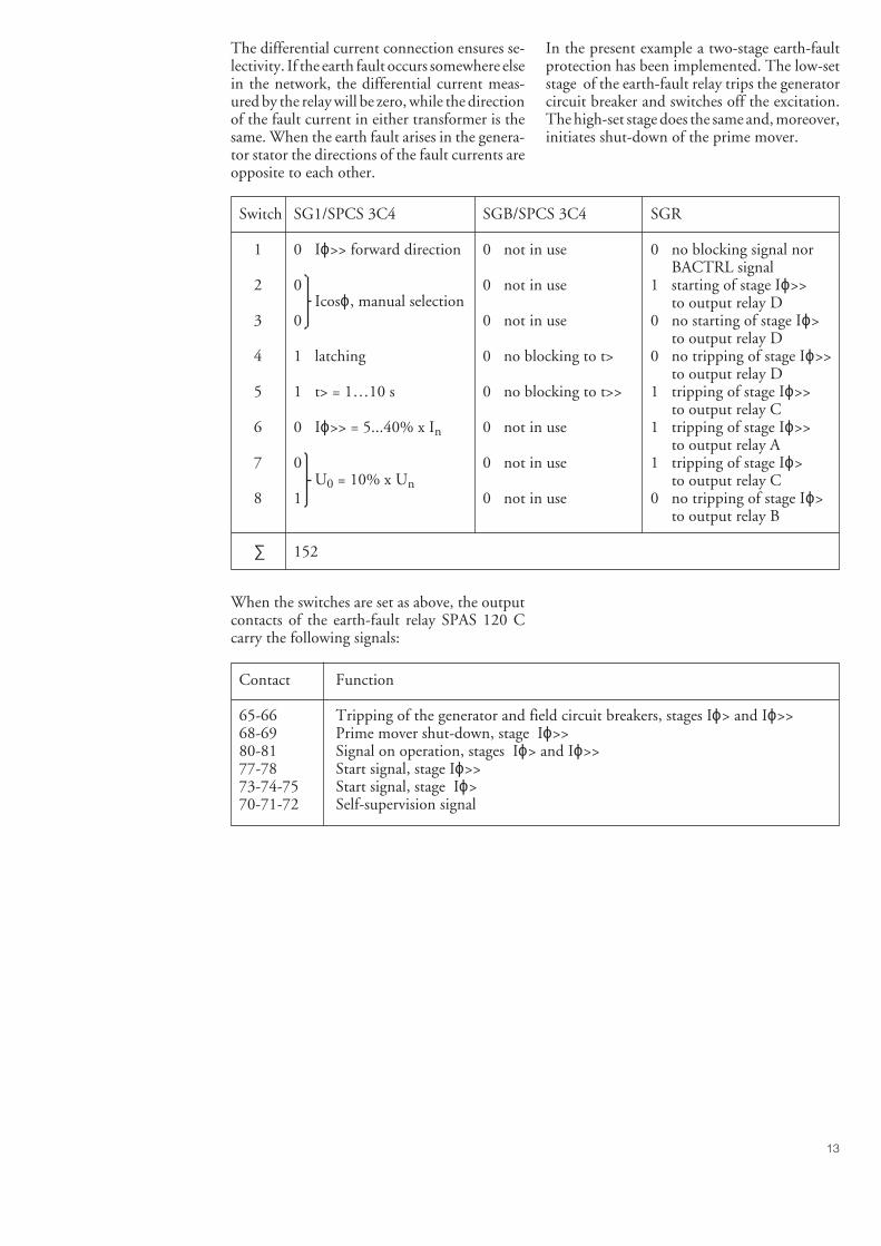
The differential current connection ensures se-lectivity. If the earth fault occurs somewhere elsein the network, the differential current meas-ured by the relay will be zero, while the directionof the fault current in either transformer is thesame. When the earth fault arises in the genera-tor stator the directions of the fault currents areopposite to each other.
In the present example a two-stage earth-faultprotection has been implemented. The low-setstage of the earth-fault relay trips the generatorcircuit breaker and switches off the excitation.The high-set stage does the same and, moreover,initiates shut-down of the prime mover.
When the switches are set as above, the outputcontacts of the earth-fault relay SPAS 120 Ccarry the following signals:
Switch SG1/SPCS 3C4 SGB/SPCS 3C4 SGR
1 0 Iϕ>> forward direction 0 not in use 0 no blocking signal norBACTRL signal
2 0 0 not in use 1 starting of stage Iϕ>>to output relay D
3 0 0 not in use 0 no starting of stage Iϕ>to output relay D
4 1 latching 0 no blocking to t> 0 no tripping of stage Iϕ>>to output relay D
5 1 t> = 1…10 s 0 no blocking to t>> 1 tripping of stage Iϕ>>to output relay C
6 0 Iϕ>> = 5...40% x In 0 not in use 1 tripping of stage Iϕ>>to output relay A
7 0 0 not in use 1 tripping of stage Iϕ>to output relay C
8 1 0 not in use 0 no tripping of stage Iϕ>to output relay B
∑ 152
U0 = 10% x Un
Icosϕ, manual selection
Contact Function
65-66 Tripping of the generator and field circuit breakers, stages Iϕ> and Iϕ>>68-69 Prime mover shut-down, stage Iϕ>>80-81 Signal on operation, stages Iϕ> and Iϕ>>77-78 Start signal, stage Iϕ>>73-74-75 Start signal, stage Iϕ>70-71-72 Self-supervision signal
14
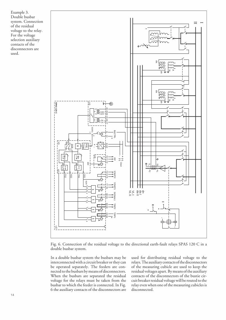
Example 3.Double busbarsystem. Connectionof the residualvoltage to the relay.For the voltageselection auxiliarycontacts of thedisconnectors areused.
Fig. 6. Connection of the residual voltage to the directional earth-fault relays SPAS 120 C in adouble busbar system.
In a double busbar system the busbars may beinterconnected with a circuit breaker or they canbe operated separately. The feeders are con-nected to the busbars by means of disconnectors.When the busbars are separated the residualvoltage for the relays must be taken from thebusbar to which the feeder is connected. In Fig.6 the auxiliary contacts of the disconnectors are
used for distributing residual voltage to therelays. The auxiliary contacts of the disconnectorsof the measuring cubicle are used to keep theresidual voltages apart. By means of the auxiliarycontacts of the disconnectors of the bustie cir-cuit breaker residual voltage will be routed to therelay even when one of the measuring cubicles isdisconnected.
SPA
S 120 C
U2
U3
U3
11
1
CB
A
+
1 D
+-
Uaux
E
+-(~)(~)
100V110V
5A1A
6566
6968
8180
7877
7271
70
SG
R3
24
75
86
6212
1127
2625
3029
2861~
STA
RT
1S
IGN
AL1
TR
IP2
TR
IP1
STA
RT
2IR
FB
AC
TR
L
IRF
7475
73
F
TS
2
TS
1
SS
1
SS
2
U1
I/O
t >>
t >Iϕ
>
Iϕ>>
+
P1
P2
S1
S_
0
I
0I
-
-
+ +
+dnda IIda I
II I
VL II
VL I
AN
da
dn
SG
R/1
SG
B
5 4 sinϕcosϕ
0
1
AN
da
dn
15
Fig. 7. Connection of residual voltage to the relay in a double busbar system.
SPA
S 1
20 C
U2
U3
U3
11
1
CB
A
+
1
D
+-
Uau
x
E
+ -(~
)(~
)
100V110V
5A1A
6566
6968
8180
7877
7271
70
SG
R3
24
75
86
6212
1127
2625
3029
2861 ~
STA
RT
1S
IGN
AL1
TR
IP2
TR
IP1
STA
RT
2IR
FB
AC
TR
L
IRF
7475
73
F
TS
2
TS
1
SS
1
SS
2
U1
I/O
t >>
t >Iϕ
>
Iϕ>>
≅
100V110V
SG
R/1
U2
U3
U3
11
11
DC
BA
+-
E
SG
R
2829
3010
11
Uau
x+ -
(~)
(~)
6162
7071
7277
7880
8168
6965
66
75
32
46
8
SPA
U 1
10 C
_
STA
RT
1S
IGN
AL1
TR
IP2
TR
IP1
IRF
BS
IRF
SG
B
SS
1
U154
I/O
t >>
t >U
o>
Uo>
>
TS
1
SS
2
TS
2
7475
73
F
STA
RT
2
≅
100V110V
SG
R/1
U2
U3
U3
11
11
DC
BA
+-
E
SG
R
2829
3010
11
Uau
x+ -
(~)
(~)
6162
7071
7277
7880
8168
6965
66
75
32
46
8
SPA
U 1
10 C
_
STA
RT
1S
IGN
AL1
TR
IP2
TR
IP1
IRF
BS
IRF
SG
B
SS
1
U1
54
I/O
t >>
t >U
o>
Uo>
>
TS
1
SS
2
TS
2
7475
73
F
STA
RT
2
0
I
0 I
-
-
++
dn
da II
da I
III
R
-P
1
P2
S2
S1
+
--
++
+
A N
da
dn
SG
R/1
SG
B
54sinϕ co
sϕ
0
1
A N
da
dn
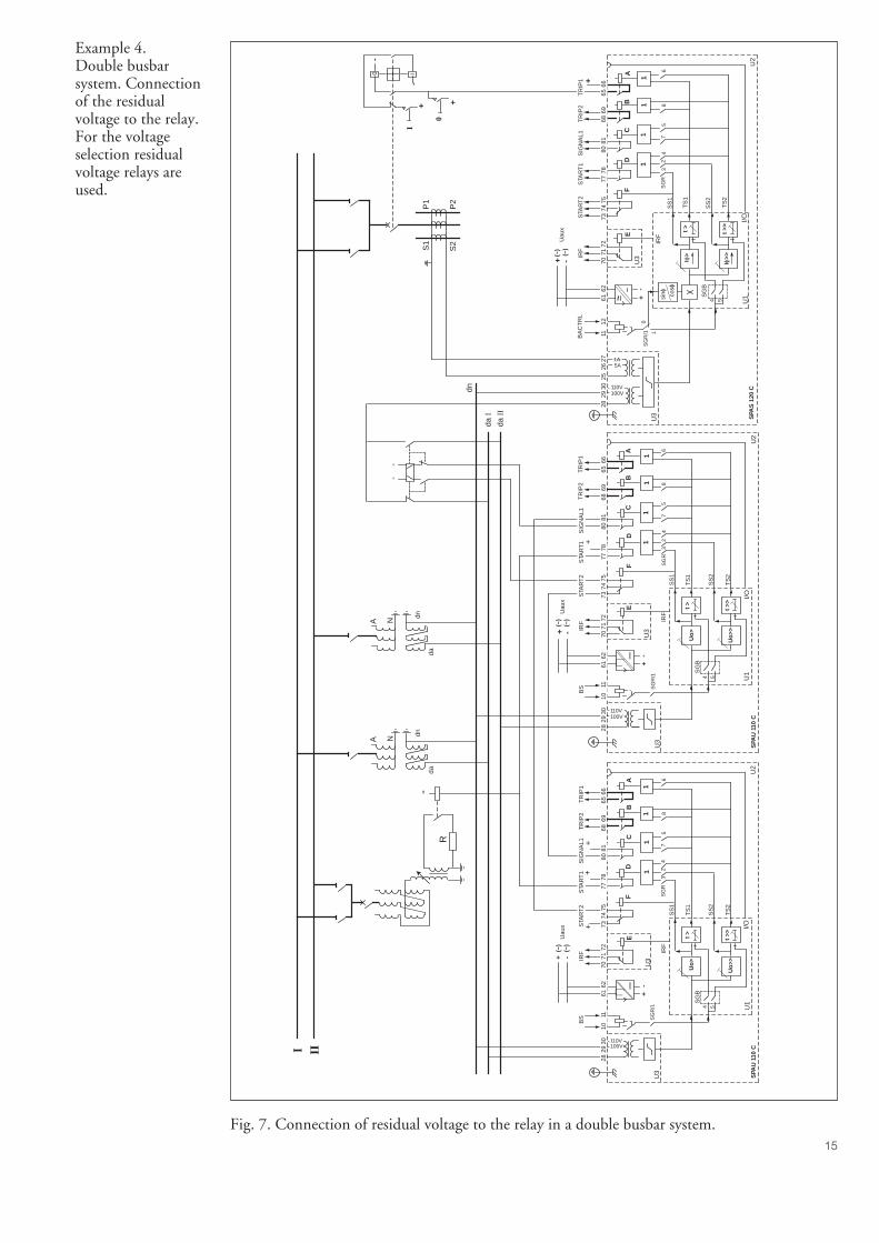
Example 4.Double busbarsystem. Connectionof the residualvoltage to the relay.For the voltageselection residualvoltage relays areused.
16
In Ex. 4 a residual voltage relay SPAU 110 Cand a bistable auxiliary relay are used for thedistribution of residual voltage. The residualvoltage of the busbar to which the faulty feederis connected is automatically connected to therelay. When the busbars are interconnected theresidual voltage is fed from one busbar only.When the busbars are separated it is assumedthat there will not be two earth faults at the sametime in two different network parts connectedto different busbars.
The start contact of the residual voltage relaycan be used for controlling the switching deviceof the parallel resistor of the arc suppression coil.
In Figs. 3 and 4, for control of the operationcharacteristic I0sinϕ or I0cosϕ auxiliary con-tacts of the disconnectors and the switchingdevice of the arc suppression coil can be used.
The data recorded in the registers of the relaycan be used both to analyze an earth-fault situ-ation and to study the behaviour of the protec-tion equipment.
Register 1 records measured I0sinϕ or I0cosϕvalue as a percentage of the rated current. Theregister is updated when one of Iϕ> or Iϕ>>protection stages starts or operates. When therelay starts but does not operate, the relay mod-ule memorizes the maximum Iϕ during the startsituation. A second exceeding of Iϕ> or Iϕ>>protection stage will erase previously recordedvalue and starts to record a new maximum U0value. When a stage operates, the value of Iϕmeasured at the moment of operation is re-corded.
Register 2 records measured residual voltage U0value as a percentage of the rated voltage Un.The register is updated when one of Iϕ> or Iϕ>>protection stages starts or operates. When therelay starts but does not operate, the relay mod-ule memorizes the maximum U0 during thestart situation. A second exceeding of Iϕ> orIϕ>> protection stage will erase previously re-corded value and starts to record a new maxi-mum U0 value. When a stage operates, the valueof U0 measured at the moment of operation isrecorded.
The data of register 1, 2 and 8 shows how closethe relay settings are to the real fault current andvoltage values. Correspondingly, the ratio be-tween the set start values and the current andvoltage values during normal operation can bedetermined by reading the normal current andvoltage values via the display of the relay.
The recorded residual voltage and current val-ues can be used for determining the fault resist-ance value. In this way the fault reason can bededuced and the fault location can be estimated.
The number of times the different stages havestarted, registers 3, 4 and 5, provides informa-tion on the fault frequency. Frequent starts maybe a sign of an imminent earth fault, e.g. a faultyisolator or some kind of disturbance apt to causean earth-fault, e.g. tree branch touching the line.
Registers 6 and 7 show the duration of the lateststart situation of the stages, expressed in per centof the set operate time. Any new start resets thecounter, which restarts from zero. If the stageoperates, the register value will be 100.
The registers 6 and 7 provide information onthe duration of an earth fault, or, if a final triphas been performed, the safety margin of thegrading times of the selective protection. Thisinformation is useful for checking the set values.
Register 8 records measured neutral current I0value as a percentage of the rated current In.The operation principle is the same as that ofregister 2. *)
*) From the program version 068 D (012 F) andlater version this register 8 has been incorporatedinto the relay module.
Registers 1...8 are reset either by pressing theSTEP and RESET push-buttons simultaneouslyor by giving a command V102 via the SPA bus.
Recorded dataand fault analysis(modified 2000-02)
17
Testing, both primary and secondary, shouldalways be performed in accordance with na-tional regulations and instructions.
The protection relay incorporates an IRF func-tion that continuously monitors the internalstate of the relay and produces an alarm signal onthe detection of a fault. According to the manu-facturer’s recommendations the relay should besubmitted to secondary testing at five years’intervals. These tests should include the entireprotection chain from the instrument trans-formers to the circuit breakers.
The secondary testing described in this manualis based on the relay’s setting values duringnormal operation. If necessary, the secondarytesting can be extended by testing the protectionstages throughout their setting ranges.
As switch positions and setting values have to bealtered during the test procedure the correctpositions of switches and the setting values ofthe relay during normal operation conditionshave to be recorded, for instance, on the refer-ence card accompanying the relay.
For secondary testing the relay must be dis-connected, either using disconnectable terminalblocks or a test adapter fitted on the relay.
DANGER!Do not open the secondary circuit of a currenttransformer under any phases of the testing, ifthe primary circuit is live. The high voltageproduced by an open CT secondary circuitcould be lethal and may damage instrumentsand insulation.
When auxiliary voltage is connected to theprotection relay, the relay performs a self-testingprogram, which does not include the matchingtransformers and the contacts of the outputrelays. The operational condition of the relay istested by means of ordinary relay test equipmentand such a test also includes the matching trans-formers, the output relays and the accuracy ofthe operate values.
Equipment required for testing:- adjustable ac voltage source 0...40 V- adjustable ac current source 4 mA…5 A- ammeter, accuracy ±0.5%- voltmeter- stop watch or counter for time measurement- dc voltage source- switches and indicator lamps- supply and pilot wires- calibrated multimeter
The secondary current of the current trans-former is to be selected on the basis of the ratedcurrent, 1 A or 5 A, of the relay energizing inputto be tested. The energizing inputs are specifiedunder the heading "Technical data, Energizinginputs".
Secondaryinjection testing
18
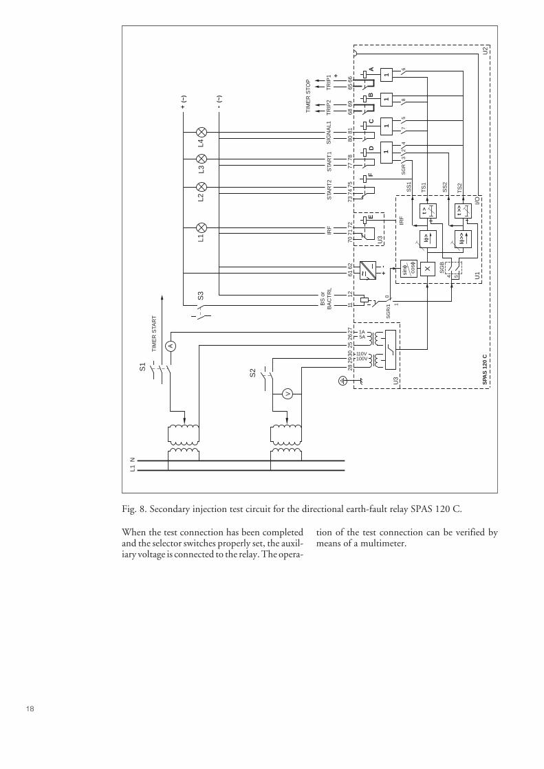
Fig. 8. Secondary injection test circuit for the directional earth-fault relay SPAS 120 C.
When the test connection has been completedand the selector switches properly set, the auxil-iary voltage is connected to the relay. The opera-
tion of the test connection can be verified bymeans of a multimeter.
SPA
S 1
20 C
U2
U3
U3
11
1
CB
A
+
1D
+-
E
100V110V
5A1A
6566
6968
8180
7877
7271
70
SG
R3
24
75
86
6212
1127
2625
3029
2861 ~
STA
RT
1S
IGN
AL1
TR
IP2
TR
IP1
STA
RT
2IR
FB
S o
rB
AC
TR
L
IRF
7475
73
F
TS
2
TS
1
SS
1
SS
2
I/O
t >>
t >Iϕ
>
Iϕ>>
+(~
)
-(~
)
A
TIM
ER
STA
RT
S1
S3
L2L3
L1L4
V
NL1
TIM
ER
ST
OP
U1
SG
R/1
SG
B
54sinϕ co
sϕ
0
1
S2
19
Apply voltage and current to the relay andcompare the current value indicated on thedisplay of the relay with that shown by the
meters. The measurements can be made for theenergizing inputs used in the application.
Testing of thematchingtransformers
Testing of thelow-set stage Iϕ>
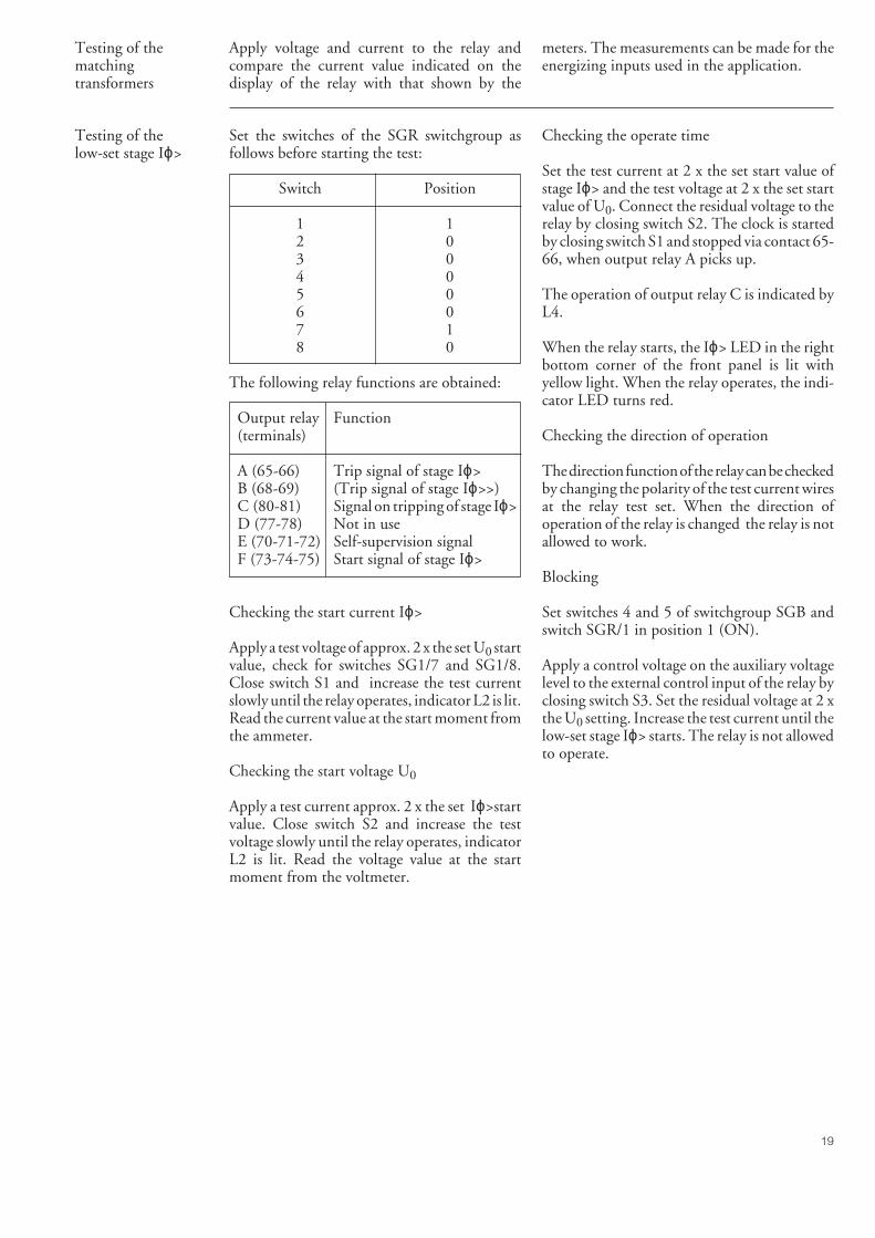
Set the switches of the SGR switchgroup asfollows before starting the test:
Switch Position
1 12 03 04 05 06 07 18 0
The following relay functions are obtained:
Output relay Function(terminals)
A (65-66) Trip signal of stage Iϕ>B (68-69) (Trip signal of stage Iϕ>>)C (80-81) Signal on tripping of stage Iϕ>D (77-78) Not in useE (70-71-72) Self-supervision signalF (73-74-75) Start signal of stage Iϕ>
Checking the start current Iϕ>
Apply a test voltage of approx. 2 x the set U0 startvalue, check for switches SG1/7 and SG1/8.Close switch S1 and increase the test currentslowly until the relay operates, indicator L2 is lit.Read the current value at the start moment fromthe ammeter.
Checking the start voltage U0
Apply a test current approx. 2 x the set Iϕ>startvalue. Close switch S2 and increase the testvoltage slowly until the relay operates, indicatorL2 is lit. Read the voltage value at the startmoment from the voltmeter.
Checking the operate time
Set the test current at 2 x the set start value ofstage Iϕ> and the test voltage at 2 x the set startvalue of U0. Connect the residual voltage to therelay by closing switch S2. The clock is startedby closing switch S1 and stopped via contact 65-66, when output relay A picks up.
The operation of output relay C is indicated byL4.
When the relay starts, the Iϕ> LED in the rightbottom corner of the front panel is lit withyellow light. When the relay operates, the indi-cator LED turns red.
Checking the direction of operation
The direction function of the relay can be checkedby changing the polarity of the test current wiresat the relay test set. When the direction ofoperation of the relay is changed the relay is notallowed to work.
Blocking
Set switches 4 and 5 of switchgroup SGB andswitch SGR/1 in position 1 (ON).
Apply a control voltage on the auxiliary voltagelevel to the external control input of the relay byclosing switch S3. Set the residual voltage at 2 xthe U0 setting. Increase the test current until thelow-set stage Iϕ> starts. The relay is not allowedto operate.
20
Testing of thehigh-set stage Iϕ>>
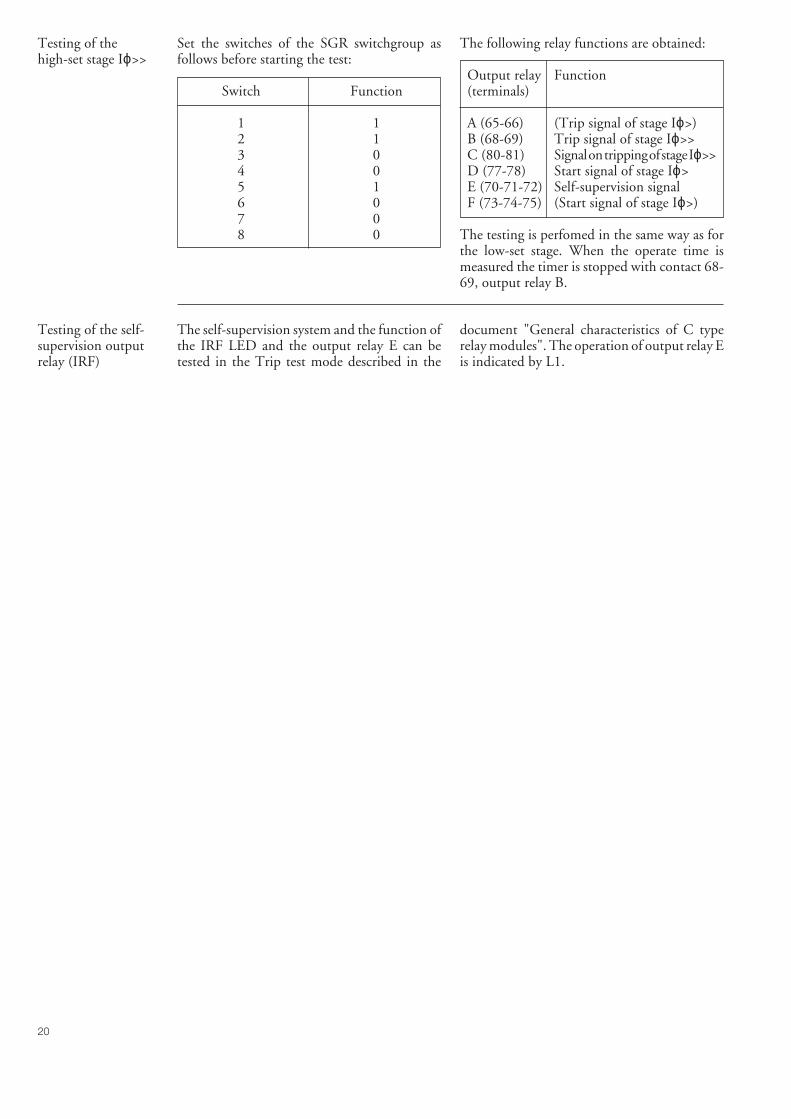
Set the switches of the SGR switchgroup asfollows before starting the test:
Switch Function
1 12 13 04 05 16 07 08 0
The following relay functions are obtained:
Output relay Function(terminals)
A (65-66) (Trip signal of stage Iϕ>)B (68-69) Trip signal of stage Iϕ>>C (80-81) Signal on tripping of stage Iϕ>>D (77-78) Start signal of stage Iϕ>E (70-71-72) Self-supervision signalF (73-74-75) (Start signal of stage Iϕ>)
The testing is perfomed in the same way as forthe low-set stage. When the operate time ismeasured the timer is stopped with contact 68-69, output relay B.
Testing of the self-supervision outputrelay (IRF)
The self-supervision system and the function ofthe IRF LED and the output relay E can betested in the Trip test mode described in the
document "General characteristics of C typerelay modules". The operation of output relay Eis indicated by L1.
21
When used under the conditions specified inthe section "Technical data", the relay requirespractically no maintenance. The relay includesno parts or components that are sensitive toabnormal physical or electrical wear under nor-mal operating conditions.
If the environmental conditions on site differfrom those specified, as to temperature andhumidity, or if the atmosphere around the relaycontains chemically active gases or dust, therelay should be visually inspected during therelay secondary testing. The visual inspectionshould focus on:
- Signs of mechanical damage to relay case andterminals
- Dust accumulated inside the relay cover orcase; remove carefully with compressed air ora soft brush
- Signs of corrosion on terminals, case or com-ponents inside the relay
If the relay fails in operation or if the operationvalues considerably differ from those stated inthe relay specifications, the relay should be givena proper overhaul. Minor measures, such asexchange of a faulty module, can be taken bypersonnel from the customer’s instrument work-shop, but major measures involving the elec-tronics are to be taken by the manufacturer.Please contact the manufacturer or his nearestrepresentative for further information aboutchecking, overhaul and calibration of the relay.
Note!The protection relays contain electronic circuitswhich are sensitive to damage due to electro-static discharge. Before removing a module,ensure that you are at the same electrostaticpotential as the equipment by touching the case.
Note!Static protection relays are measuring instru-ments and should be handled with care andprotected against damp and mechanical stress,especially during transport and storage.
Maintenanceand repair
Exchange andspare parts
Directional earth-fault relay module SPCS 3C4Combined power supply and I/O module- Uaux = 80...265 V ac/dc SPTU 240S1- Uaux = 18...80 V dc SPTU 48S1Case (including I/O module) SPTK 2E13I/O module SPTE 2E13Bus connection module SPA-ZC 17_ or SPA-ZC 21_
Directional earth-fault relay without test adapterSPAS 120 C RS 431 010 -AA, CA, DA, FA
Directional earth-fault relay with test adapter RTXP 18SPAS 120 C RS 431 210 -AA, CA, DA, FA
The last two letters of the ordering number designate the rated frequency fn andthe Uaux voltage range of the relay as follows:
AA: fn = 50 Hz and Uaux = 80...265 V ac/dcCA: fn = 50 Hz and Uaux = 18...80 V dcDA: fn = 60 Hz and Uaux = 80...265 V ac/dcFA: fn = 60 Hz and Uaux = 18...80 V dc
Orderingnumbers
22
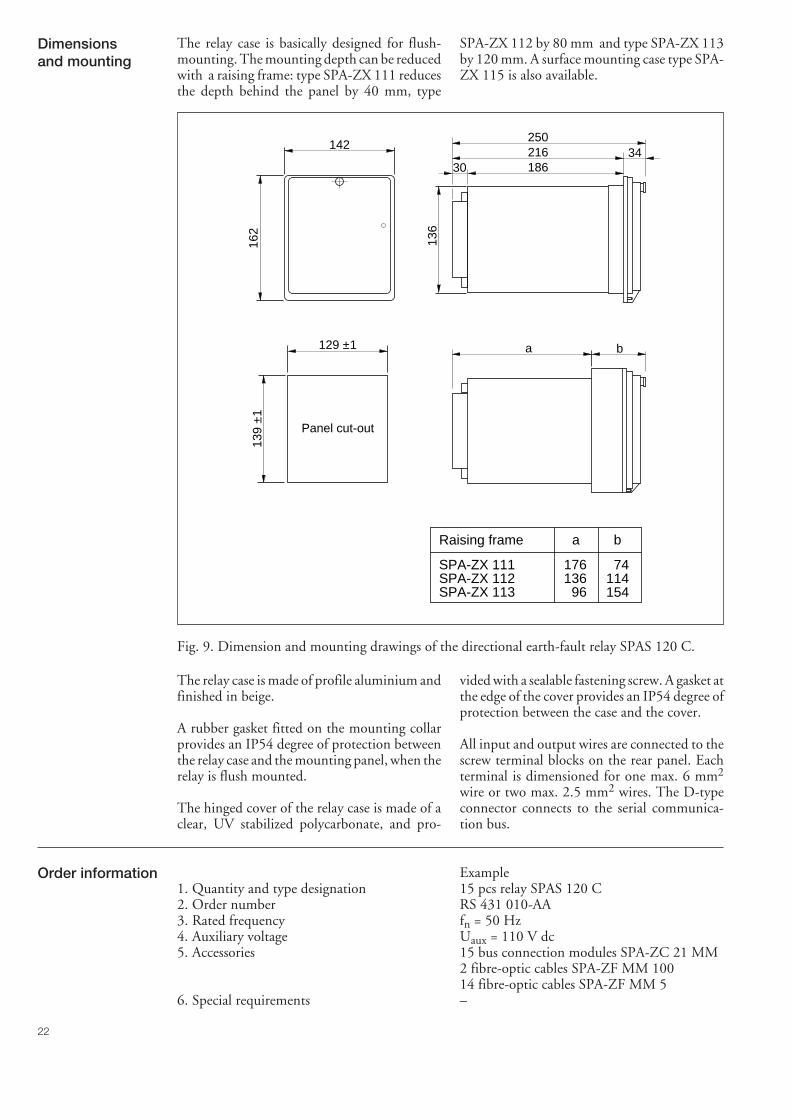
Dimensionsand mounting
The relay case is basically designed for flush-mounting. The mounting depth can be reducedwith a raising frame: type SPA-ZX 111 reducesthe depth behind the panel by 40 mm, type
SPA-ZX 112 by 80 mm and type SPA-ZX 113by 120 mm. A surface mounting case type SPA-ZX 115 is also available.
Order information Example1. Quantity and type designation 15 pcs relay SPAS 120 C2. Order number RS 431 010-AA3. Rated frequency fn = 50 Hz4. Auxiliary voltage Uaux = 110 V dc5. Accessories 15 bus connection modules SPA-ZC 21 MM
2 fibre-optic cables SPA-ZF MM 10014 fibre-optic cables SPA-ZF MM 5
6. Special requirements –
Fig. 9. Dimension and mounting drawings of the directional earth-fault relay SPAS 120 C.
The relay case is made of profile aluminium andfinished in beige.
A rubber gasket fitted on the mounting collarprovides an IP54 degree of protection betweenthe relay case and the mounting panel, when therelay is flush mounted.
The hinged cover of the relay case is made of aclear, UV stabilized polycarbonate, and pro-
vided with a sealable fastening screw. A gasket atthe edge of the cover provides an IP54 degree ofprotection between the case and the cover.
All input and output wires are connected to thescrew terminal blocks on the rear panel. Eachterminal is dimensioned for one max. 6 mm2
wire or two max. 2.5 mm2 wires. The D-typeconnector connects to the serial communica-tion bus.
Raising frame
SPA-ZX 111SPA-ZX 112SPA-ZX 113
176136 96
74114154
a b
a b
Panel cut-out
129 ±1
139
±1
142
162
136
3034
250
186216
SPCS 3C4Overcurrent relay module
User´s manual and Technical description
o IRF
0047
A
0.6
0.1 1.0
30
5
0.6
0.1 1.0
1.0
6.0
10
STEP
RESET
SG1
0 1
1234567840
SPCS 3C4
BI
>>Iϕ>Iϕ
[ ]s>t
nI
nI
>>t [ ]s
>I ϕ
>>I ϕ [ ]%
[ ]%
U oI ϕI
STEP
2
1MRS 750350-MUM EN
Issued 1996-03-14Modified 2000-02-16Version C (replaces 34 SPCS 1 EN1)CheckedApproved
Data subject to change without notice
SPCS 3C4Overcurrent relay module
Contents Features .......................................................................................................................... 2Description of operation ................................................................................................. 3Block schematic diagram ................................................................................................ 4Front panel ..................................................................................................................... 5Operation indicators ....................................................................................................... 5Settings ........................................................................................................................... 6Selector switches ............................................................................................................. 7Measured data ................................................................................................................ 9Recorded information (modified 2000-02) .................................................................... 10Main menus and submenus of settings and registers ..................................................... 12Technical data (modified 2000-02) ............................................................................... 13Event codes ................................................................................................................... 14Remote transfer data (modified 2000-02) ...................................................................... 15Fault codes .................................................................................................................... 18
Features Directional neutral overcurrent relay modulewith definite time characteristic for earth faultprotection
Two neutral overcurrent stages, a low-set stageIϕ> and a high-set stage Iϕ>>
The high-set stage can be given the same or theopposite direction of operation as comparedwith the low-set stage
I0sinϕ or I0cosϕ operation characteristic se-lected locally by switches or by remote controlover the external control input
Four selectable start values for the residual volt-age
Digital display of measured values, set valuesand recorded fault values
Continuous self-supervision with autodiagnos-tics including both hardware and software
Serial communication capability for extensivedata exchange between the relay module and thesubstation level communication or control sys-tem
3
The directional neutral overcurrent relay mod-ule SPCS 3C4 measures the residual voltage U0and the active component I0cosϕ or the reactivecomponent I0sinϕ of the neutral current I0. Thephase angle ϕ is the phase displacement betweenthe measured voltage and current.
The module starts, generating a start signal SS1or SS2, if I0cosϕ or I0sinϕ exceeds the set startvalue Iϕ> or Iϕ>>, and the neutral voltagesimultaneously exceeds the selected start voltagevalue. The operation indicator of the stage whichstarts is lit with yellow light. If the situationpersists long enough, the stage which startedalso operates generating a trip signal TS1 orTS2. Simultaneously, the yellow operation in-dicator of the concerned stage turns red. Theoperation indicators can be given self-reset ormanual-reset mode of operation. If the manualreset mode of operation has been selected theoperation indicator can be reset by pushing theRESET push button or by remote control viathe SPA bus using the command V101 or V102.
The operation of the low-set stage Iϕ> can beblocked by routing a blocking signal BTS1 tothe stage. In the same way the operation of stageIϕ>> is blocked by means of the blocking signalBTS2. The external blocking signals are con-figured by means of switchgroup SGB locatedon the PC board of the relay module.
If the directional neutral overcurrent relay mod-ule is cooperating with auto-reclose relay mod-ule, switchgroup SGB is additionally used forthe selection of start initiation signals for theauto-reclose module. See also paragraph "Signaldiagram" in the general manual of the differentprotection relays.
The direction of operation of the stages is se-lected with switch SG1/1. The low-set stage Iϕ>operates in the forward direction only, the high-set stage Iϕ>> can be set to operate in eitherdirection (see fig. 4).
The start value of the residual voltage is selectedwith switches SG1/7 and SG1/8. Four alterna-tive start values are available.
The operation characteristics of the module arepresented in Fig. 4. If the system to be protectedis resonant earthed or solidly or nearly solidlyearthed, the operation characteristic to be se-lected is I0cosϕ, whereas I0sinϕ is selected forthe protection of isolated neutral systems.
The operation characteristic, I0sinϕ or I0cosϕ,can be selected manually by means of switchSG1/3 on the front panel of the relay module,when SG1/2 = 0. If SG1/2 = 1, the operationcharacteristic can be remotely controlled irre-spective of the position of switch SG1/3. Bybringing a control signal named BACTRL tothe 0 state the operation characteristic will beI0sinϕ. When the control signal BACTRL is inthe 1 state, the operation characteristic is I0cosϕ.If the operation characteristic is to be automati-cally controlled, the change from I0sinϕ toI0cosϕ or vice versa is initiated by an auxiliarycontact of the disconnector of the earthing coil.
The setting range of the operation time t> of thelow-set stage Iϕ> is selected with switch SG1/5.Two setting ranges are available.
The setting range of the start current of the high-set stage Iϕ>>, i.e. 5...40% x In or 1...8% x In, isselected with switch SG1/6. Additionally theoperation of the high-set stage can be set out offunction by selecting the setting ∞, infinite.
The operation outputs TS1 and TS2 of the twostages are provided with a so called latchingfunction (switch SG1/4). If selected, the opera-tion output and thus the output relay will re-main energized, although the signal which causedoperation disappears. The stages are reset bypushing the STEP and RESET push buttonssimultaneously or by remote control via the SPAbus using the command V101 or V102. See alsotable (for switchgroup SG3) on page 9 in chap-ter "Selector switches".
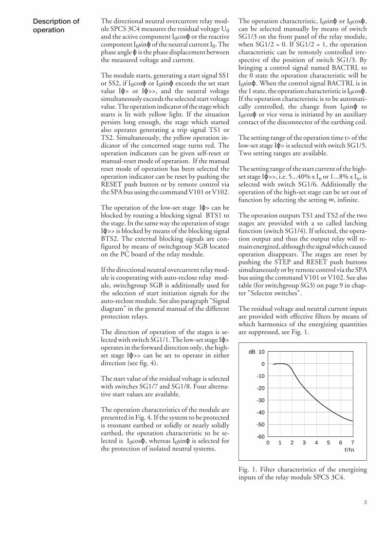
The residual voltage and neutral current inputsare provided with effective filters by means ofwhich harmonics of the energizing quantitiesare suppressed, see Fig. 1.
Description ofoperation
dB 10
0
-10
-20
-30
-40
-50
-600 1 2 3 4 5 6 7 f / fn
Fig. 1. Filter characteristics of the energizinginputs of the relay module SPCS 3C4.
4
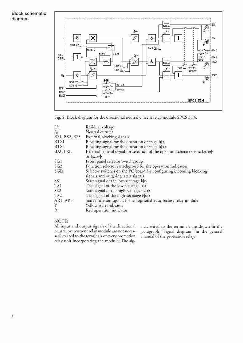
Block schematicdiagram
Fig. 2. Block diagram for the directional neutral current relay module SPCS 3C4.
U0 Residual voltageI0 Neutral currentBS1, BS2, BS3 External blocking signalsBTS1 Blocking signal for the operation of stage Iϕ>BTS2 Blocking signal for the operation of stage Iϕ>>BACTRL External control signal for selection of the operation characteristic I0sinϕ
or I0cosϕSG1 Front panel selector switchgroupSG2 Function selector switchgroup for the operation indicatorsSGB Selector switches on the PC board for configuring incoming blocking
signals and outgoing start signalsSS1 Start signal of the low-set stage Iϕ>TS1 Trip signal of the low-set stage Iϕ>SS2 Start signal of the high-set stage Iϕ>>TS2 Trip signal of the high-set stage Iϕ>>AR1, AR3 Start initiation signals for an optional auto-reclose relay moduleY Yellow start indicatorR Red operation indicator
NOTE!All input and output signals of the directionalneutral overcurrent relay module are not neces-sarily wired to the terminals of every protectionrelay unit incorporating the module. The sig-
nals wired to the terminals are shown in theparagraph "Signal diagram" in the generalmanual of the protection relay.
5
Front panel
On-display indicators for themeasured parameters U0, I0 and Iϕ,i.e. I0sinϕ or I0cosϕ
Setting knop and indicator for thestart current of stage Iϕ>
Setting knop and indicator for theoperate time of stage Iϕ>
Setting knop and indicator for thestart current of stage Iϕ>>
Setting knop and indicator for theoperate time of stage Iϕ>>
Simplified apparatussymbol
Self-supervision alarmindicator (IRF)
Display for set andmeasured values
Display step push button
Selector switchgroupSG1
Indicators forswitchgroupsSG1, SG2 and SG3
Reset push button
Operation indicators forstage Iϕ> and stage Iϕ>>Relay module typedesignation
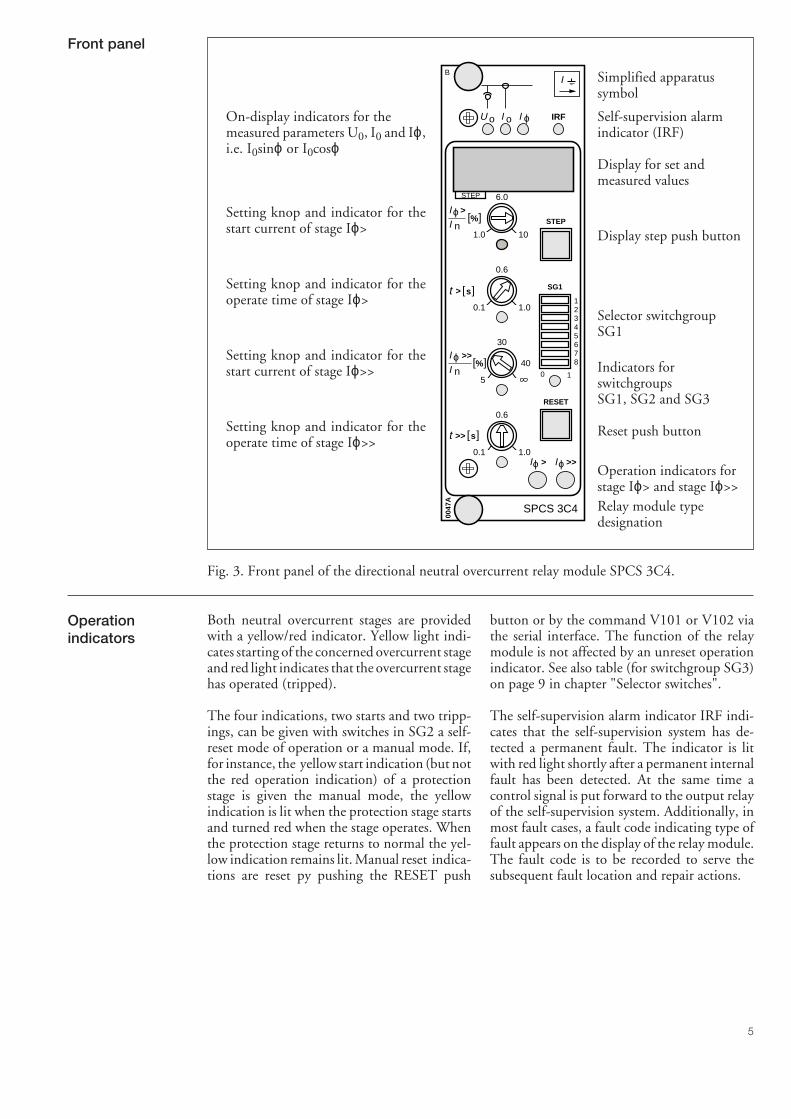
Fig. 3. Front panel of the directional neutral overcurrent relay module SPCS 3C4.
Both neutral overcurrent stages are providedwith a yellow/red indicator. Yellow light indi-cates starting of the concerned overcurrent stageand red light indicates that the overcurrent stagehas operated (tripped).
The four indications, two starts and two tripp-ings, can be given with switches in SG2 a self-reset mode of operation or a manual mode. If,for instance, the yellow start indication (but notthe red operation indication) of a protectionstage is given the manual mode, the yellowindication is lit when the protection stage startsand turned red when the stage operates. Whenthe protection stage returns to normal the yel-low indication remains lit. Manual reset indica-tions are reset py pushing the RESET push
button or by the command V101 or V102 viathe serial interface. The function of the relaymodule is not affected by an unreset operationindicator. See also table (for switchgroup SG3)on page 9 in chapter "Selector switches".
The self-supervision alarm indicator IRF indi-cates that the self-supervision system has de-tected a permanent fault. The indicator is litwith red light shortly after a permanent internalfault has been detected. At the same time acontrol signal is put forward to the output relayof the self-supervision system. Additionally, inmost fault cases, a fault code indicating type offault appears on the display of the relay module.The fault code is to be recorded to serve thesubsequent fault location and repair actions.
Operationindicators
o IRF
0047
A
0.6
0.1 1.0
30
5
0.6
0.1 1.0
1.0
6.0
10
STEP
RESET
SG1
0 1
1234567840
SPCS 3C4
BI
>>Iϕ>Iϕ
[ ]s>t
nI
nI
>>t [ ]s
>I ϕ
>>I ϕ [ ]%
[ ]%
U oI ϕI
STEP
6
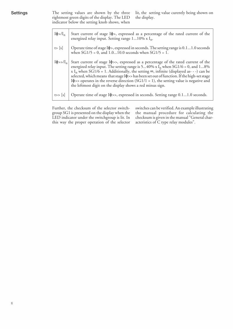
lit, the setting value curently being shown onthe display.
Settings The setting values are shown by the threerightmost green digits of the display. The LEDindicator below the setting knob shows, when
Iϕ>/In Start current of stage Iϕ>, expressed as a percentage of the rated current of theenergized relay input. Setting range 1...10% x In.
t> [s] Operate time of stage Iϕ>, expressed in seconds. The setting range is 0.1...1.0 secondswhen SG1/5 = 0, and 1.0...10.0 seconds when SG1/5 = 1.
Iϕ>>/In Start current of stage Iϕ>>, expressed as a percentage of the rated current of theenergized relay input. The setting range is 5...40% x In when SG1/6 = 0, and 1...8%x In when SG1/6 = 1. Additionally, the setting ∞, infinite (displayed as- - -) can beselected, which means that stage Iϕ>> has been set out of function. If the high-set stageIϕ>> operates in the reverse direction (SG1/1 = 1), the setting value is negative andthe leftmost digit on the display shows a red minus sign.
t>> [s] Operate time of stage Iϕ>>, expressed in seconds. Setting range 0.1...1.0 seconds.
Further, the checksum of the selector switch-group SG1 is presented on the display when theLED indicator under the switchgroup is lit. Inthis way the proper operation of the selector
switches can be verified. An example illustratingthe manual procedure for calculating thechecksum is given in the manual "General char-acteristics of C type relay modules".
7
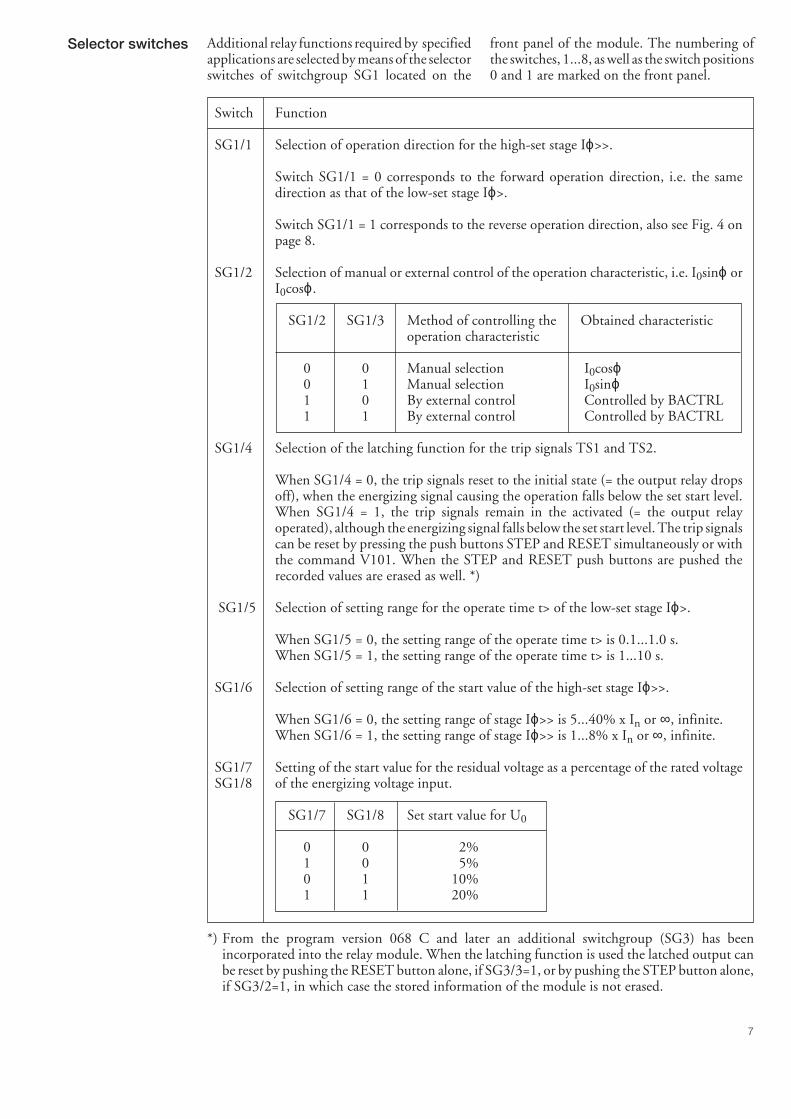
front panel of the module. The numbering ofthe switches, 1...8, as well as the switch positions0 and 1 are marked on the front panel.
Selector switches Additional relay functions required by specifiedapplications are selected by means of the selectorswitches of switchgroup SG1 located on the
Switch Function
SG1/1 Selection of operation direction for the high-set stage Iϕ>>.
Switch SG1/1 = 0 corresponds to the forward operation direction, i.e. the samedirection as that of the low-set stage Iϕ>.
Switch SG1/1 = 1 corresponds to the reverse operation direction, also see Fig. 4 onpage 8.
SG1/2 Selection of manual or external control of the operation characteristic, i.e. I0sinϕ orI0cosϕ.
SG1/2 SG1/3 Method of controlling the Obtained characteristicoperation characteristic
0 0 Manual selection I0cosϕ0 1 Manual selection I0sinϕ1 0 By external control Controlled by BACTRL1 1 By external control Controlled by BACTRL
SG1/4 Selection of the latching function for the trip signals TS1 and TS2.
When SG1/4 = 0, the trip signals reset to the initial state (= the output relay dropsoff), when the energizing signal causing the operation falls below the set start level.When SG1/4 = 1, the trip signals remain in the activated (= the output relayoperated), although the energizing signal falls below the set start level. The trip signalscan be reset by pressing the push buttons STEP and RESET simultaneously or withthe command V101. When the STEP and RESET push buttons are pushed therecorded values are erased as well. *)
SG1/5 Selection of setting range for the operate time t> of the low-set stage Iϕ>.
When SG1/5 = 0, the setting range of the operate time t> is 0.1...1.0 s.When SG1/5 = 1, the setting range of the operate time t> is 1...10 s.
SG1/6 Selection of setting range of the start value of the high-set stage Iϕ>>.
When SG1/6 = 0, the setting range of stage Iϕ>> is 5...40% x In or ∞, infinite.When SG1/6 = 1, the setting range of stage Iϕ>> is 1...8% x In or ∞, infinite.
SG1/7 Setting of the start value for the residual voltage as a percentage of the rated voltageSG1/8 of the energizing voltage input.
SG1/7 SG1/8 Set start value for U0
0 0 2%1 0 5%0 1 10%1 1 20%
*) From the program version 068 C and later an additional switchgroup (SG3) has beenincorporated into the relay module. When the latching function is used the latched output canbe reset by pushing the RESET button alone, if SG3/3=1, or by pushing the STEP button alone,if SG3/2=1, in which case the stored information of the module is not erased.
8
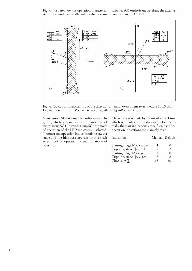
Fig. 4 illustrates how the operation characteris-tic of the module are affected by the selector
switches SG1 on the front panel and the externalcontrol signal BACTRL.
Fig. 4. Operation characteristic of the directional neutral overcurrent relay module SPCS 3C4.Fig. 4a shows the I0sinϕ characteristic, Fig. 4b the I0cosϕ characteristic.
Switchgroup SG2 is a so called software switch-group, which is located in the third submenu ofswitchgroup SG1. In switchgroup SG2 the modeof operation of the LED indicators is selected.The start and operation indicators of the low-setstage and the high-set stage can be given selfreset mode of operation or manual mode ofoperation.
The selection is made by means of a checksumwhich is calculated from the table below. Nor-mally the start indications are self reset and theoperation indications are manualy reset.
Indication Manual Default
Starting, stage Iϕ>, yellow 1 0Tripping, stage Iϕ>, red 2 2Starting, stage Iϕ>>, yellow 4 0Tripping, stage Iϕ>>, red 8 8Checksum ∑ 15 10
9
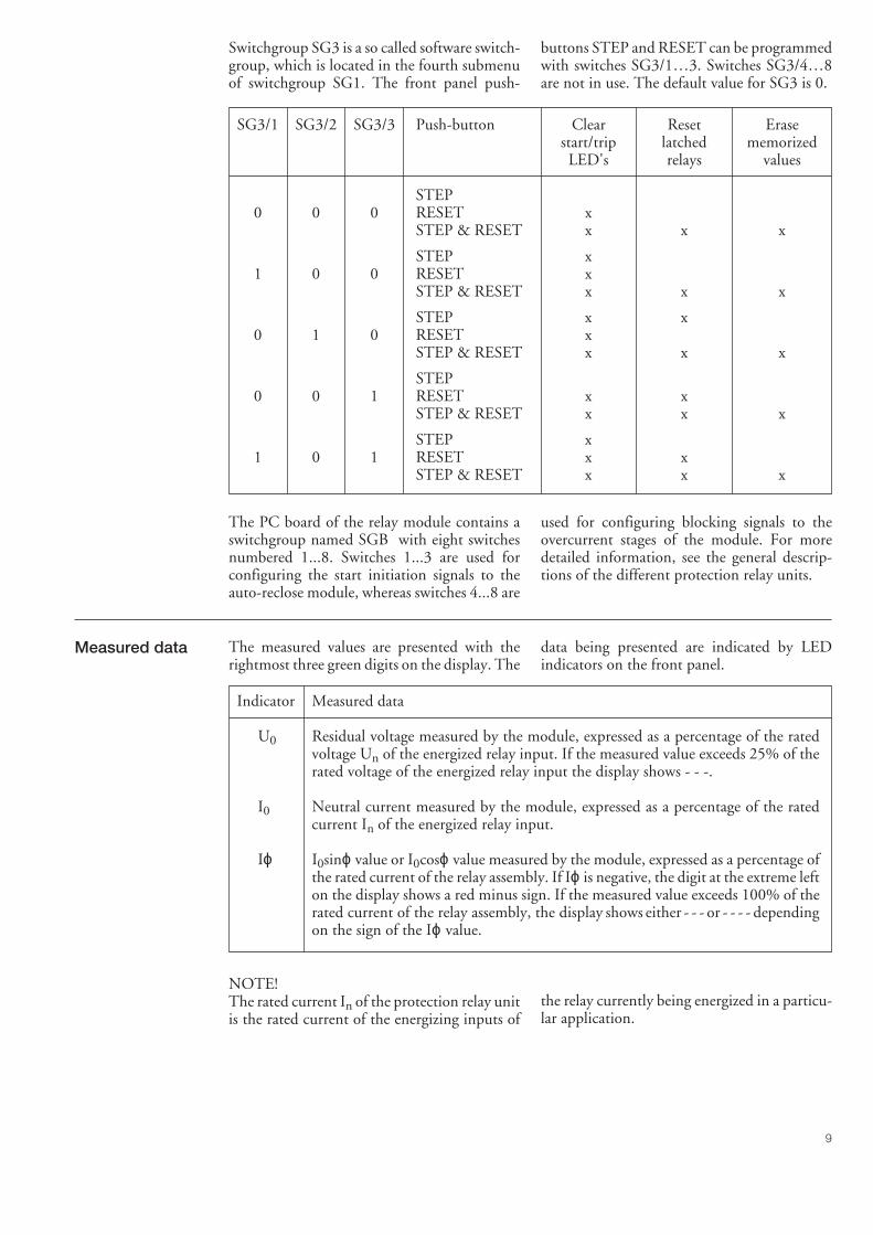
Switchgroup SG3 is a so called software switch-group, which is located in the fourth submenuof switchgroup SG1. The front panel push-
buttons STEP and RESET can be programmedwith switches SG3/1…3. Switches SG3/4…8are not in use. The default value for SG3 is 0.
SG3/1 SG3/2 SG3/3 Push-button Clear Reset Erasestart/trip latched memorizedLED's relays values
STEP0 0 0 RESET x
STEP & RESET x x x
STEP x1 0 0 RESET x
STEP & RESET x x x
STEP x x0 1 0 RESET x
STEP & RESET x x x
STEP0 0 1 RESET x x
STEP & RESET x x x
STEP x1 0 1 RESET x x
STEP & RESET x x x
The PC board of the relay module contains aswitchgroup named SGB with eight switchesnumbered 1...8. Switches 1...3 are used forconfiguring the start initiation signals to theauto-reclose module, whereas switches 4...8 are
used for configuring blocking signals to theovercurrent stages of the module. For moredetailed information, see the general descrip-tions of the different protection relay units.
data being presented are indicated by LEDindicators on the front panel.
Indicator Measured data
U0 Residual voltage measured by the module, expressed as a percentage of the ratedvoltage Un of the energized relay input. If the measured value exceeds 25% of therated voltage of the energized relay input the display shows - - -.
I0 Neutral current measured by the module, expressed as a percentage of the ratedcurrent In of the energized relay input.
Iϕ I0sinϕ value or I0cosϕ value measured by the module, expressed as a percentage ofthe rated current of the relay assembly. If Iϕ is negative, the digit at the extreme lefton the display shows a red minus sign. If the measured value exceeds 100% of therated current of the relay assembly, the display shows either - - - or - - - - dependingon the sign of the Iϕ value.
Measured data The measured values are presented with therightmost three green digits on the display. The
NOTE!The rated current In of the protection relay unitis the rated current of the energizing inputs of
the relay currently being energized in a particu-lar application.
10
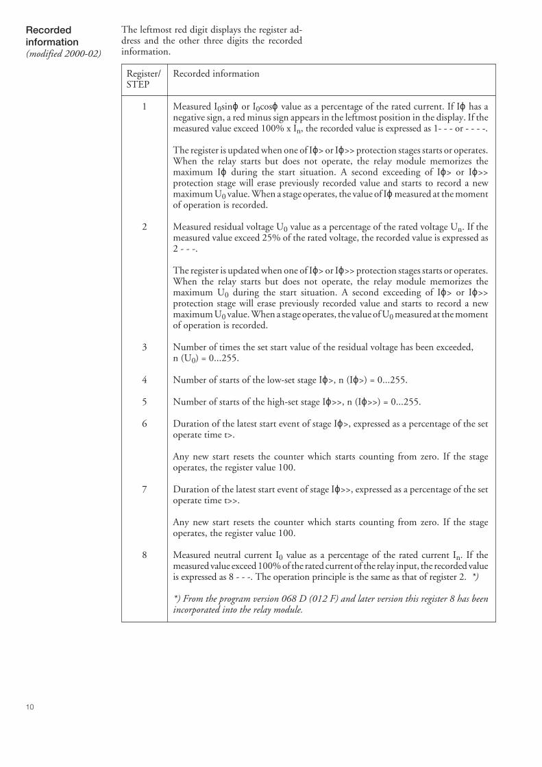
Register/ Recorded informationSTEP
1 Measured I0sinϕ or I0cosϕ value as a percentage of the rated current. If Iϕ has anegative sign, a red minus sign appears in the leftmost position in the display. If themeasured value exceed 100% x In, the recorded value is expressed as 1- - - or - - - -.
The register is updated when one of Iϕ> or Iϕ>> protection stages starts or operates.When the relay starts but does not operate, the relay module memorizes themaximum Iϕ during the start situation. A second exceeding of Iϕ> or Iϕ>>protection stage will erase previously recorded value and starts to record a newmaximum U0 value. When a stage operates, the value of Iϕ measured at the momentof operation is recorded.
2 Measured residual voltage U0 value as a percentage of the rated voltage Un. If themeasured value exceed 25% of the rated voltage, the recorded value is expressed as2 - - -.
The register is updated when one of Iϕ> or Iϕ>> protection stages starts or operates.When the relay starts but does not operate, the relay module memorizes themaximum U0 during the start situation. A second exceeding of Iϕ> or Iϕ>>protection stage will erase previously recorded value and starts to record a newmaximum U0 value. When a stage operates, the value of U0 measured at the momentof operation is recorded.
3 Number of times the set start value of the residual voltage has been exceeded,n (U0) = 0...255.
4 Number of starts of the low-set stage Iϕ>, n (Iϕ>) = 0...255.
5 Number of starts of the high-set stage Iϕ>>, n (Iϕ>>) = 0...255.
6 Duration of the latest start event of stage Iϕ>, expressed as a percentage of the setoperate time t>.
Any new start resets the counter which starts counting from zero. If the stageoperates, the register value 100.
7 Duration of the latest start event of stage Iϕ>>, expressed as a percentage of the setoperate time t>>.
Any new start resets the counter which starts counting from zero. If the stageoperates, the register value 100.
8 Measured neutral current I0 value as a percentage of the rated current In. If themeasured value exceed 100% of the rated current of the relay input, the recorded valueis expressed as 8 - - -. The operation principle is the same as that of register 2. *)
*) From the program version 068 D (012 F) and later version this register 8 has beenincorporated into the relay module.
Recordedinformation(modified 2000-02)
The leftmost red digit displays the register ad-dress and the other three digits the recordedinformation.
11
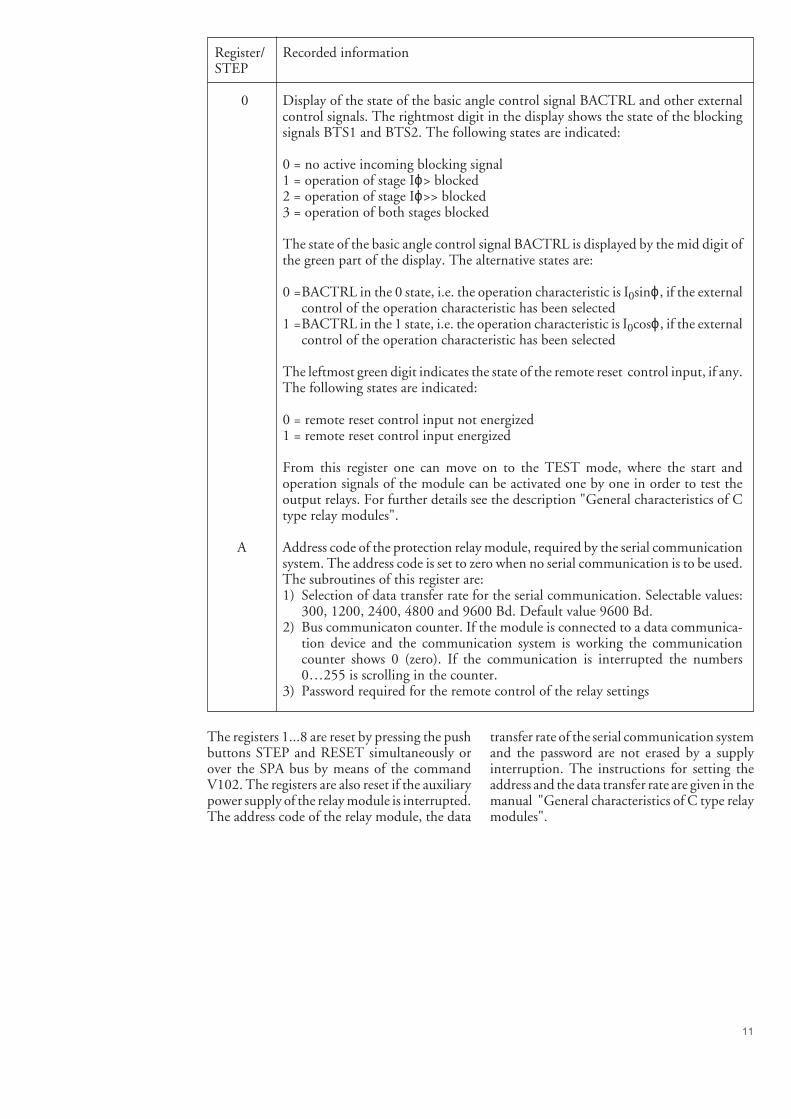
Register/ Recorded informationSTEP
0 Display of the state of the basic angle control signal BACTRL and other externalcontrol signals. The rightmost digit in the display shows the state of the blockingsignals BTS1 and BTS2. The following states are indicated:
0 = no active incoming blocking signal1 = operation of stage Iϕ> blocked2 = operation of stage Iϕ>> blocked3 = operation of both stages blocked
The state of the basic angle control signal BACTRL is displayed by the mid digit ofthe green part of the display. The alternative states are:
0 =BACTRL in the 0 state, i.e. the operation characteristic is I0sinϕ, if the externalcontrol of the operation characteristic has been selected
1 =BACTRL in the 1 state, i.e. the operation characteristic is I0cosϕ, if the externalcontrol of the operation characteristic has been selected
The leftmost green digit indicates the state of the remote reset control input, if any.The following states are indicated:
0 = remote reset control input not energized1 = remote reset control input energized
From this register one can move on to the TEST mode, where the start andoperation signals of the module can be activated one by one in order to test theoutput relays. For further details see the description "General characteristics of Ctype relay modules".
A Address code of the protection relay module, required by the serial communicationsystem. The address code is set to zero when no serial communication is to be used.The subroutines of this register are:1) Selection of data transfer rate for the serial communication. Selectable values:
300, 1200, 2400, 4800 and 9600 Bd. Default value 9600 Bd.2) Bus communicaton counter. If the module is connected to a data communica-
tion device and the communication system is working the communicationcounter shows 0 (zero). If the communication is interrupted the numbers0…255 is scrolling in the counter.
3) Password required for the remote control of the relay settings
The registers 1...8 are reset by pressing the pushbuttons STEP and RESET simultaneously orover the SPA bus by means of the commandV102. The registers are also reset if the auxiliarypower supply of the relay module is interrupted.The address code of the relay module, the data
transfer rate of the serial communication systemand the password are not erased by a supplyinterruption. The instructions for setting theaddress and the data transfer rate are given in themanual "General characteristics of C type relaymodules".
12
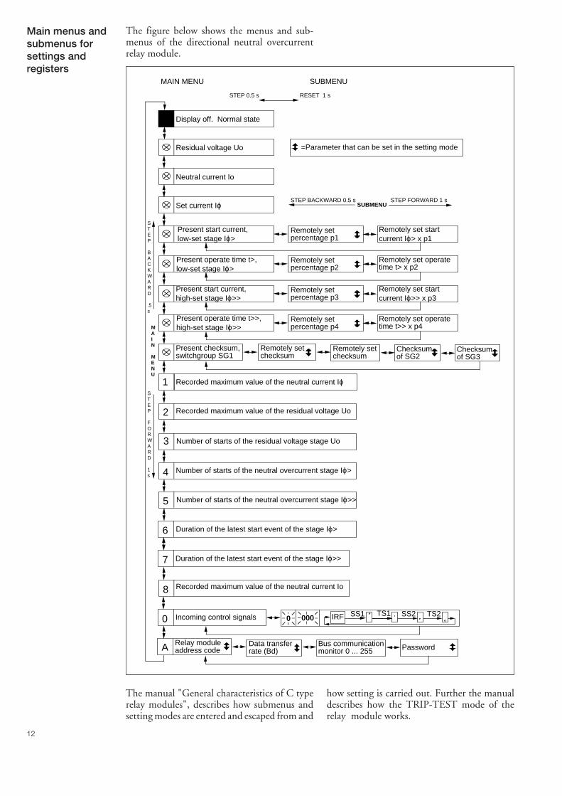
The manual "General characteristics of C typerelay modules", describes how submenus andsetting modes are entered and escaped from and
how setting is carried out. Further the manualdescribes how the TRIP-TEST mode of therelay module works.
Main menus andsubmenus forsettings andregisters
The figure below shows the menus and sub-menus of the directional neutral overcurrentrelay module.
Display off. Normal state
SUBMENUSTEP FORWARD 1 sSTEP BACKWARD 0.5 s
STEP
BACKWARD
.5s
STEP
FORWARD
1s
MAIN MENU SUBMENU
STEP 0.5 s RESET 1 s
Residual voltage Uo
MAIN
MENU
Remotely setpercentage p1
Present start current, low-set stage Iϕ>
Remotely set startcurrent Iϕ> x p1
Remotely setpercentage p2
Present operate time t>, low-set stage Iϕ>
Remotely set operatetime t> x p2
Remotely setpercentage p3
Present start current, high-set stage Iϕ>>
Remotely set start current Iϕ>> x p3
Remotely setpercentage p4
Present operate time t>>, high-set stage Iϕ>>
Remotely set operatetime t>> x p4
Present checksum,switchgroup SG1
Remotely setchecksum
Remotely set checksum
Checksumof SG2
Recorded maximum value of the neutral current Iϕ
Recorded maximum value of the residual voltage Uo
Number of starts of the residual voltage stage Uo
1
2
3
4
0 000 SS1 TS1 TS2IRF SS2Incoming control signals0
Relay moduleaddress code
Data transferrate (Bd)
Bus communicationmonitor 0 ... 255 PasswordA
=Parameter that can be set in the setting mode
Neutral current Io
Set current Iϕ
Number of starts of the neutral overcurrent stage Iϕ>
5 Number of starts of the neutral overcurrent stage Iϕ>>
6 Duration of the latest start event of the stage Iϕ>
7 Duration of the latest start event of the stage Iϕ>>
Checksumof SG3
8 Recorded maximum value of the neutral current Io
13
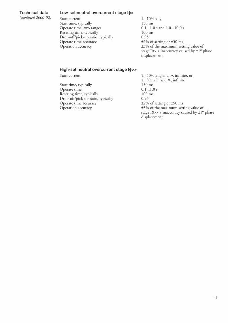
Low-set neutral overcurrent stage Iϕ>Start current 1...10% x InStart time, typically 150 msOperate time, two ranges 0.1...1.0 s and 1.0...10.0 sReseting time, typically 100 msDrop-off/pick-up ratio, typically 0.95Operate time accuracy ±2% of setting or ±50 msOperation accuracy ±3% of the maximum setting value of
stage Iϕ> + inaccuracy caused by ±1o phasedisplacement
High-set neutral overcurrent stage Iϕ>>Start current 5...40% x In and ∞, infinite, or
1...8% x In and ∞, infiniteStart time, typically 150 msOperate time 0.1...1.0 sReseting time, typically 100 msDrop-off/pick-up ratio, typically 0.95Operate time accuracy ±2% of setting or ±50 msOperation accuracy ±3% of the maximum setting value of
stage Iϕ>> + inaccuracy caused by ±1o phasedisplacement
Technical data(modified 2000-02)
14
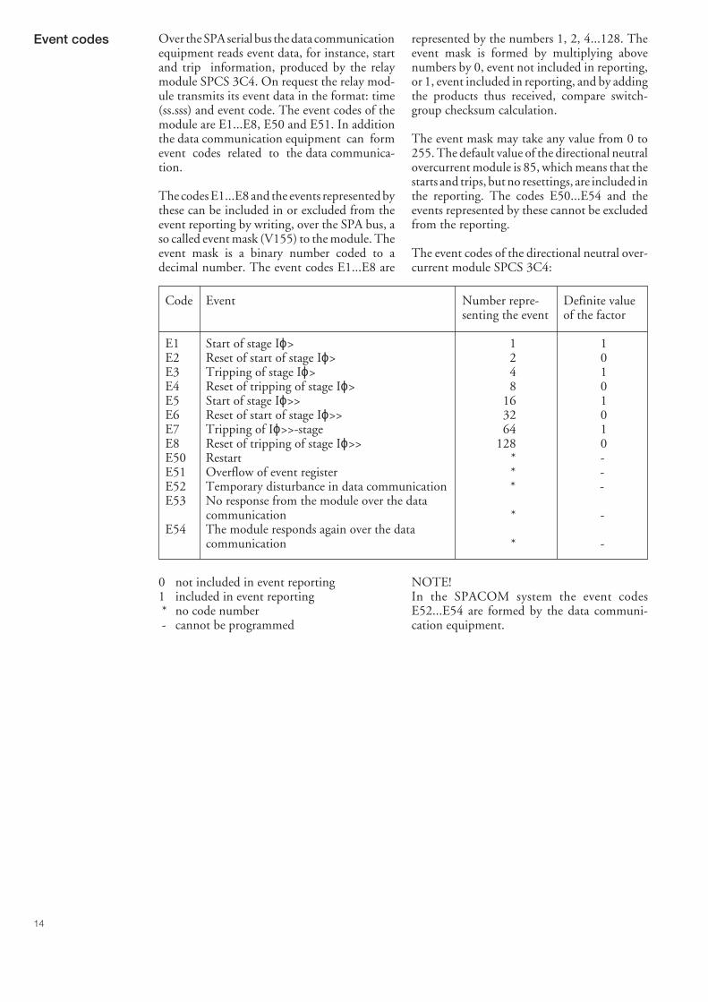
represented by the numbers 1, 2, 4...128. Theevent mask is formed by multiplying abovenumbers by 0, event not included in reporting,or 1, event included in reporting, and by addingthe products thus received, compare switch-group checksum calculation.
The event mask may take any value from 0 to255. The default value of the directional neutralovercurrent module is 85, which means that thestarts and trips, but no resettings, are included inthe reporting. The codes E50...E54 and theevents represented by these cannot be excludedfrom the reporting.
The event codes of the directional neutral over-current module SPCS 3C4:
Code Event Number repre- Definite valuesenting the event of the factor
E1 Start of stage Iϕ> 1 1E2 Reset of start of stage Iϕ> 2 0E3 Tripping of stage Iϕ> 4 1E4 Reset of tripping of stage Iϕ> 8 0E5 Start of stage Iϕ>> 16 1E6 Reset of start of stage Iϕ>> 32 0E7 Tripping of Iϕ>>-stage 64 1E8 Reset of tripping of stage Iϕ>> 128 0E50 Restart * -E51 Overflow of event register * -E52 Temporary disturbance in data communication * -E53 No response from the module over the data
communication * -E54 The module responds again over the data
communication * -
Event codes Over the SPA serial bus the data communicationequipment reads event data, for instance, startand trip information, produced by the relaymodule SPCS 3C4. On request the relay mod-ule transmits its event data in the format: time(ss.sss) and event code. The event codes of themodule are E1...E8, E50 and E51. In additionthe data communication equipment can formevent codes related to the data communica-tion.
The codes E1...E8 and the events represented bythese can be included in or excluded from theevent reporting by writing, over the SPA bus, aso called event mask (V155) to the module. Theevent mask is a binary number coded to adecimal number. The event codes E1...E8 are
0 not included in event reporting1 included in event reporting * no code number - cannot be programmed
NOTE!In the SPACOM system the event codesE52...E54 are formed by the data communi-cation equipment.
15
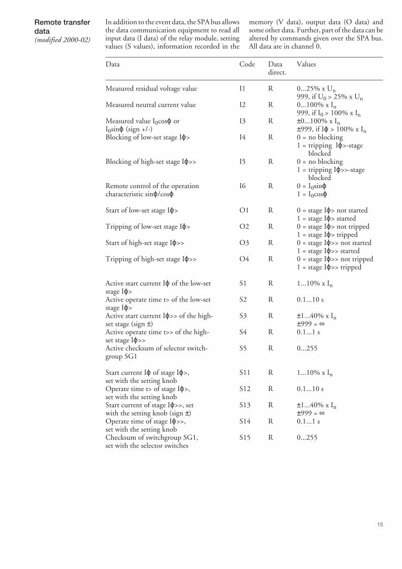
Remote transferdata(modified 2000-02)
memory (V data), output data (O data) andsome other data. Further, part of the data can bealtered by commands given over the SPA bus.All data are in channel 0.
In addition to the event data, the SPA bus allowsthe data communication equipment to read allinput data (I data) of the relay module, settingvalues (S values), information recorded in the
Data Code Data Valuesdirect.
Measured residual voltage value I1 R 0...25% x Un999, if U0 > 25% x Un
Measured neutral current value I2 R 0...100% x In999, if I0 > 100% x In
Measured value I0cosϕ or I3 R ±0...100% x InI0sinϕ (sign +/-) ±999, if Iϕ > 100% x InBlocking of low-set stage Iϕ> I4 R 0 = no blocking
1 = tripping Iϕ>-stageblocked
Blocking of high-set stage Iϕ>> I5 R 0 = no blocking1 = tripping Iϕ>>-stage
blockedRemote control of the operation I6 R 0 = I0sinϕcharacteristic sinϕ/cosϕ 1 = I0cosϕ
Start of low-set stage Iϕ> O1 R 0 = stage Iϕ> not started1 = stage Iϕ> started
Tripping of low-set stage Iϕ> O2 R 0 = stage Iϕ> not tripped1 = stage Iϕ> tripped
Start of high-set stage Iϕ>> O3 R 0 = stage Iϕ>> not started1 = stage Iϕ>> started
Tripping of high-set stage Iϕ>> O4 R 0 = stage Iϕ>> not tripped1 = stage Iϕ>> tripped
Active start current Iϕ of the low-set S1 R 1...10% x Instage Iϕ>Active operate time t> of the low-set S2 R 0.1...10 sstage Iϕ>Active start current Iϕ>> of the high- S3 R ±1...40% x Inset stage (sign ±) ±999 = ∞Active operate time t>> of the high- S4 R 0.1...1 sset stage Iϕ>>Active checksum of selector switch- S5 R 0...255group SG1
Start current Iϕ of stage Iϕ>, S11 R 1...10% x Inset with the setting knobOperate time t> of stage Iϕ>, S12 R 0.1...10 sset with the setting knobStart current of stage Iϕ>>, set S13 R ±1...40% x Inwith the setting knob (sign ±) ±999 = ∞Operate time of stage Iϕ>>, S14 R 0.1...1 sset with the setting knobChecksum of switchgroup SG1, S15 R 0...255set with the selector switches
16
Data Code Data Valuesdirect.
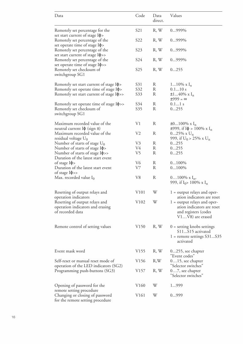
Remotely set percentage for the S21 R, W 0...999%set start current of stage Iϕ>Remotely set percentage of the S22 R, W 0...999%set operate time of stage Iϕ>Remotely set percentage of the S23 R, W 0...999%set start current of stage Iϕ>>Remotely set percentage of the S24 R, W 0...999%set operate time of stage Iϕ>>Remotely set checksum of S25 R, W 0...255switchgroup SG1
Remotely set start current of stage Iϕ> S31 R 1...10% x InRemotely set operate time of stage Iϕ> S32 R 0.1...10 sRemotely set start current of stage Iϕ>> S33 R ±1...40% x In
±999 = ∞Remotely set operate time of stage Iϕ>> S34 R 0.1...1 sRemotely set checksum of S35 R 0...255switchgroup SG1
Maximum recorded value of the V1 R ±0...100% x Inneutral current Iϕ (sign ±) ±999, if Iϕ > 100% x InMaximum recorded value of the V2 R 0...25% x Unresidual voltage U0 999, if U0 > 25% x UnNumber of starts of stage U0 V3 R 0...255Number of starts of stage Iϕ> V4 R 0...255Number of starts of stage Iϕ>> V5 R 0...255Duration of the latest start eventof stage Iϕ> V6 R 0...100%Duration of the latest start event V7 R 0...100%of stage Iϕ>>Max. recorded value I0 V8 R 0…100% x In,
999, if I0> 100% x In
Resetting of output relays and V101 W 1 = output relays and oper-operation indicators ation indicators are resetResetting of output relays and V102 W 1 = output relays and oper-operation indicators and erasing ation indicators are resetof recorded data and registers (codes
V1…V8) are erased
Remote control of setting values V150 R, W 0 = setting knobs settings S11...S15 activated1 = remote settings S31...S35
activated
Event mask word V155 R, W 0...255, see chapter"Event codes"
Self-reset or manual reset mode of V156 R,W 0…15, see chapteroperation of the LED indicators (SG2) "Selector switches"Programming push-buttons (SG3) V157 R, W 0…7, see chapter
"Selector switches"
Opening of password for the V160 W 1...999remote setting procedureChanging or closing of password V161 W 0...999for the remote setting procedure
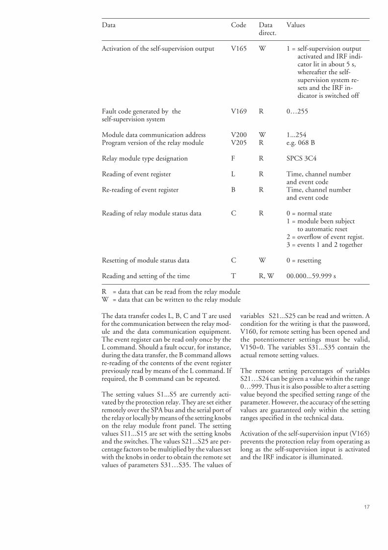
17
Data Code Data Valuesdirect.
Activation of the self-supervision output V165 W 1 = self-supervision outputactivated and IRF indi-cator lit in about 5 s,whereafter the self-supervision system re-sets and the IRF in-dicator is switched off
Fault code generated by the V169 R 0…255self-supervision system
Module data communication address V200 W 1...254Program version of the relay module V205 R e.g. 068 B
Relay module type designation F R SPCS 3C4
Reading of event register L R Time, channel numberand event code
Re-reading of event register B R Time, channel numberand event code
Reading of relay module status data C R 0 = normal state1 = module been subject to automatic reset2 = overflow of event regist.3 = events 1 and 2 together
Resetting of module status data C W 0 = resetting
Reading and setting of the time T R, W 00.000...59.999 s
R = data that can be read from the relay moduleW = data that can be written to the relay module
The data transfer codes L, B, C and T are usedfor the communication between the relay mod-ule and the data communication equipment.The event register can be read only once by theL command. Should a fault occur, for instance,during the data transfer, the B command allowsre-reading of the contents of the event registerpreviously read by means of the L command. Ifrequired, the B command can be repeated.
The setting values S1...S5 are currently acti-vated by the protection relay. They are set eitherremotely over the SPA bus and the serial port ofthe relay or locally by means of the setting knobson the relay module front panel. The settingvalues S11...S15 are set with the setting knobsand the switches. The values S21...S25 are per-centage factors to be multiplied by the values setwith the knobs in order to obtain the remote setvalues of parameters S31…S35. The values of
variables S21...S25 can be read and written. Acondition for the writing is that the password,V160, for remote setting has been opened andthe potentiometer settings must be valid,V150=0. The variables S31...S35 contain theactual remote setting values.
The remote setting percentages of variablesS21…S24 can be given a value within the range0…999. Thus it is also possible to alter a settingvalue beyond the specified setting range of theparameter. However, the accuracy of the settingvalues are guaranteed only within the settingranges specified in the technical data.
Activation of the self-supervision input (V165)prevents the protection relay from operating aslong as the self-supervision input is activatedand the IRF indicator is illuminated.
18
Fault codes Shortly after that the self-supervision system hasdetected a permanent internal fault the red IRFindicator is lit. Simultaneously the relay moduleputs forward a control signal to the output relayof the self-supervision system. In most faultsituations an autodiagnostic fault code appearson the display of the module. The fault codeconsists of a red number 1 (one), and a green,three digit code number. When a fault is de-
tected the fault code should be recorded forfurther use when the relay module is to berepaired.
Some of the fault codes that may appear on thedisplay of the directional neutral overcurrentrelay module SPCS 3C4 are shown in the fol-lowing list:
Fault code Type of fault
4 Output relay control circuit interrupted or output relay module missing30 Red Only Memory (ROM) damaged50 Random Access Memory (RAM) damaged
195 Too low a value on reference channel with multiplier 1131 Too low a value on reference channel with multiplier 5
67 Too low a value on reference channel with multiplier 25203 Too high a value on reference channel with multiplier 1139 Too high a value on reference channel with multiplier 5
75 Too high a value on reference channel with multiplier 25253 No interruptions from the A/D converter
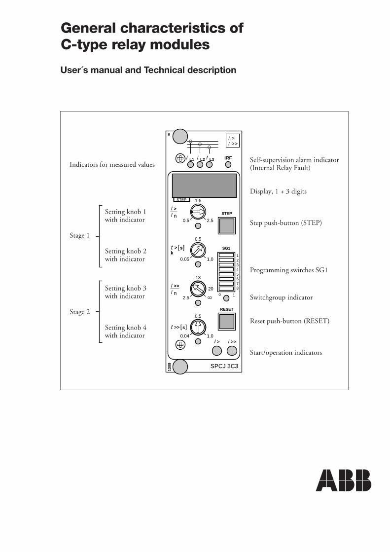
L1 IRF
>I
L2I L3II
1309
[ ]sk
>t0.5
0.05 1.0
13
2.5
0.5
0.04 1.0
0.5
1.5
2.5
STEP
RESET
SG1
0 1
1234567820
STEP
>>I
nI>I
nI>>I
>>t [ ]s
>I >>I
SPCJ 3C3
B
Indicators for measured values
Setting knob 1with indicator
Stage 1
Setting knob 2with indicator
Setting knob 3with indicator
Stage 2
Setting knob 4with indicator
Self-supervision alarm indicator(Internal Relay Fault)
Display, 1 + 3 digits
Step push-button (STEP)
Programming switches SG1
Switchgroup indicator
Reset push-button (RESET)
Start/operation indicators
General characteristics ofC-type relay modules
User´s manual and Technical description
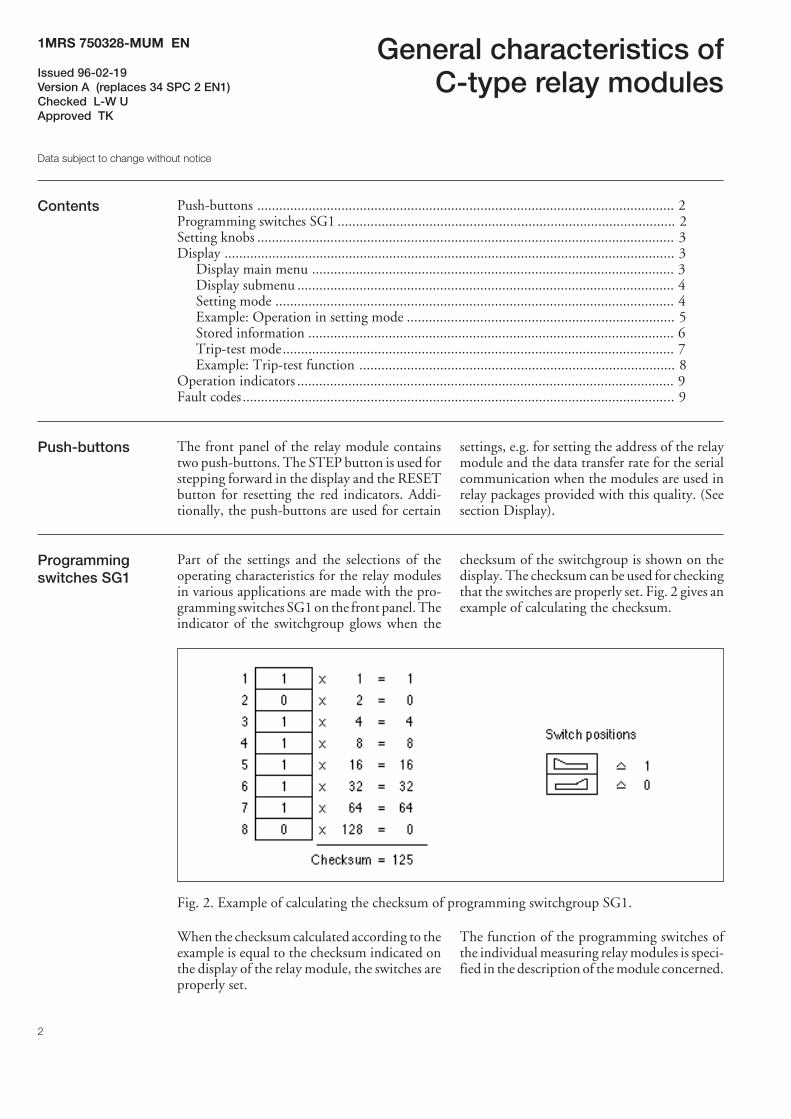
2
General characteristics ofC-type relay modules
Contents Push-buttons .................................................................................................................. 2Programming switches SG1 ............................................................................................ 2Setting knobs .................................................................................................................. 3Display ........................................................................................................................... 3
Display main menu ................................................................................................... 3Display submenu ....................................................................................................... 4Setting mode ............................................................................................................. 4Example: Operation in setting mode ......................................................................... 5Stored information .................................................................................................... 6Trip-test mode........................................................................................................... 7Example: Trip-test function ...................................................................................... 8
Operation indicators ....................................................................................................... 9Fault codes ...................................................................................................................... 9
Push-buttons The front panel of the relay module containstwo push-buttons. The STEP button is used forstepping forward in the display and the RESETbutton for resetting the red indicators. Addi-tionally, the push-buttons are used for certain
settings, e.g. for setting the address of the relaymodule and the data transfer rate for the serialcommunication when the modules are used inrelay packages provided with this quality. (Seesection Display).
Programmingswitches SG1
Part of the settings and the selections of theoperating characteristics for the relay modulesin various applications are made with the pro-gramming switches SG1 on the front panel. Theindicator of the switchgroup glows when the
checksum of the switchgroup is shown on thedisplay. The checksum can be used for checkingthat the switches are properly set. Fig. 2 gives anexample of calculating the checksum.
Fig. 2. Example of calculating the checksum of programming switchgroup SG1.
When the checksum calculated according to theexample is equal to the checksum indicated onthe display of the relay module, the switches areproperly set.
The function of the programming switches ofthe individual measuring relay modules is speci-fied in the description of the module concerned.
1MRS 750328-MUM EN
Issued 96-02-19Version A (replaces 34 SPC 2 EN1)Checked L-W UApproved TK
Data subject to change without notice
3
Setting knobs Most of the operating values and operatingtimes are set by means of the setting knobs onthe front panel of the relay module. Each settingknob has its own (LED) indicator which glowswhen the concerned setting value is shown onthe display.
If a setting knob is turned while the display isshowing another measured or set value, thevalue being set automatically appears on thedisplay. Simultaneously, the indicator for theconcerned setting starts glowing.
In addition to the settings made with the settingknobs, most modules allow so called remotesetting. This means that the settings made bymeans of the setting knobs of the module andthe checksum of the programming switchgroupmay be altered through an instruction over theserial communication bus. Remote setting ispossible if the password in the register A isknown, and the remote settings are not acti-vated, i.e. parameter V150=0. The circumstancethat the remote settings are activated is shownwith a flashing light of the indicator of thesetting knob, the value of which currently isbeing displayed.
Display The measured and set values as well as the datarecorded are shown on the display of the meas-uring relay module. The display consists of fourdigits. The three digits (green) to the rightindicate the measured, set or stored value andthe digit at the extreme left (red) the number ofthe register. The measured or set value displayedis indicated by a yellow LED indicator. Thenumber of the register glows only when a storedvalue is displayed.
When the auxiliary voltage is connected to ameasuring relay module, the module initiallytests the display by stepping through the digits1...9 for about 15 seconds. When the test isfinished the display turns dark. The testing canbe interrupted by pressing the STEP button.The protective functions of the module areoperative throughout the testing.
Display main menu All the data required during normal operatingconditions are accessible from the main menuwhich presents the measured values in real-time,the normal setting knob settings as well as themost important memorized data.
The data to be shown in the main menu areselected to the display in a certain sequence bymeans of the STEP button. When pressing theSTEP button for about one second, the displaymoves forward in the display sequence. Whenpressing it for about 0.5 seconds, the displaymoves backwards in the display sequence.
From a dark display only forward movement ispossible. When keeping the STEP button de-pressed, the display is continuously moving inforward direction stopping for a while at thedark point.
Unless the display is switched off by stepping tothe dark point, it remains activated for about 5minutes from the last pressing of the STEPbutton and then goes out.
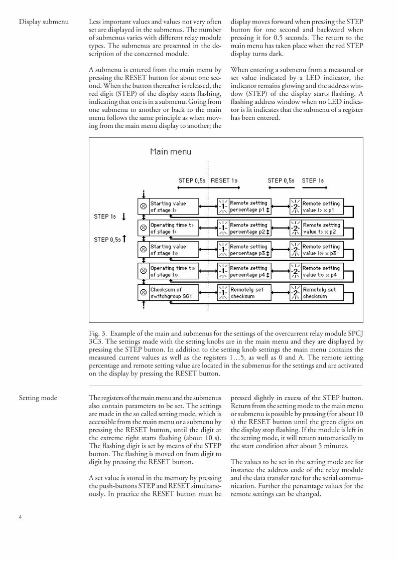
4
Display submenu Less important values and values not very oftenset are displayed in the submenus. The numberof submenus varies with different relay moduletypes. The submenus are presented in the de-scription of the concerned module.
A submenu is entered from the main menu bypressing the RESET button for about one sec-ond. When the button thereafter is released, thered digit (STEP) of the display starts flashing,indicating that one is in a submenu. Going fromone submenu to another or back to the mainmenu follows the same principle as when mov-ing from the main menu display to another; the
display moves forward when pressing the STEPbutton for one second and backward whenpressing it for 0.5 seconds. The return to themain menu has taken place when the red STEPdisplay turns dark.
When entering a submenu from a measured orset value indicated by a LED indicator, theindicator remains glowing and the address win-dow (STEP) of the display starts flashing. Aflashing address window when no LED indica-tor is lit indicates that the submenu of a registerhas been entered.
Fig. 3. Example of the main and submenus for the settings of the overcurrent relay module SPCJ3C3. The settings made with the setting knobs are in the main menu and they are displayed bypressing the STEP button. In addition to the setting knob settings the main menu contains themeasured current values as well as the registers 1…5, as well as 0 and A. The remote settingpercentage and remote setting value are located in the submenus for the settings and are activatedon the display by pressing the RESET button.
Setting mode The registers of the main menu and the submenusalso contain parameters to be set. The settingsare made in the so called setting mode, which isaccessible from the main menu or a submenu bypressing the RESET button, until the digit atthe extreme right starts flashing (about 10 s).The flashing digit is set by means of the STEPbutton. The flashing is moved on from digit todigit by pressing the RESET button.
A set value is stored in the memory by pressingthe push-buttons STEP and RESET simultane-ously. In practice the RESET button must be
pressed slightly in excess of the STEP button.Return from the setting mode to the main menuor submenu is possible by pressing (for about 10s) the RESET button until the green digits onthe display stop flashing. If the module is left inthe setting mode, it will return automatically tothe start condition after about 5 minutes.
The values to be set in the setting mode are forinstance the address code of the relay moduleand the data transfer rate for the serial commu-nication. Further the percentage values for theremote settings can be changed.
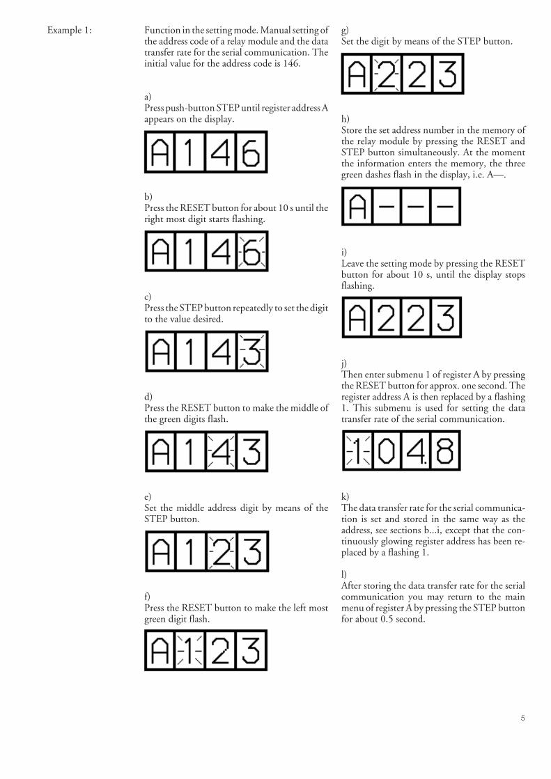
5
Example 1: Function in the setting mode. Manual setting ofthe address code of a relay module and the datatransfer rate for the serial communication. Theinitial value for the address code is 146.
a)Press push-button STEP until register address Aappears on the display.
b)Press the RESET button for about 10 s until theright most digit starts flashing.
c)Press the STEP button repeatedly to set the digitto the value desired.
d)Press the RESET button to make the middle ofthe green digits flash.
e)Set the middle address digit by means of theSTEP button.
f)Press the RESET button to make the left mostgreen digit flash.
g)Set the digit by means of the STEP button.
h)Store the set address number in the memory ofthe relay module by pressing the RESET andSTEP button simultaneously. At the momentthe information enters the memory, the threegreen dashes flash in the display, i.e. A—.
i)Leave the setting mode by pressing the RESETbutton for about 10 s, until the display stopsflashing.
j)Then enter submenu 1 of register A by pressingthe RESET button for approx. one second. Theregister address A is then replaced by a flashing1. This submenu is used for setting the datatransfer rate of the serial communication.
k)The data transfer rate for the serial communica-tion is set and stored in the same way as theaddress, see sections b...i, except that the con-tinuously glowing register address has been re-placed by a flashing 1.
l)After storing the data transfer rate for the serialcommunication you may return to the mainmenu of register A by pressing the STEP buttonfor about 0.5 second.
6
Stored information The parameter values measured at the momentwhen a fault occurs are recorded in the registers,in some modules also the setting values. Therecorded data, except for some setting param-eters, are set to zero by pressing the push-buttons STEP and RESET simul-taneously.The data in normal registers are erased if theauxiliary voltage supply to the relay is disrupted,only the set values and the number ofautoreclosings are maintained in the registers ata voltage failure.
The number of the registers varies with differentmodule types. The function of the registers areillustrated in the descriptions of the separaterelay modules. Additionally, the system panelcontains a simplified list of the data recorded bythe various relay modules of the relay assembly.
All C-type relay modules are provided with twogeneral registers: register 0 and register A.
Register 0 contains, in coded form, the informa-tion about e.g. external blocking signals andstatus information for the circuit breaker. Thecodes are explained in the descriptions of therelay modules.
Register A contains the address code of the relaymodule as required by the serial communicationsystem. Example 1 on page 4 shows how theaddress code is altered. Submenu 1 of register Acontains the data transfer rate value expressed inkilobaud for the serial communication.
Submenu 2 of register A contains a bus trafficmonitor for the SPACOM system. If the protec-tive relay, which contains the relay module, islinked to a system including the control datacommunicator and the data communicationsystem is operating, the counter reading of themonitor will be zero. Otherwise the digits 1...255are continuously rolling in the monitor.
Submenu 3 contains the password required forchanging the remote settings. The address code,the data transfer rate for the serial communica-tion and the password can be set manually or viathe serial communication bus. For manual set-ting see example 1.
The start value for the address code and thepassword is 001 and that for the data transferrate 9.6 kilobaud.
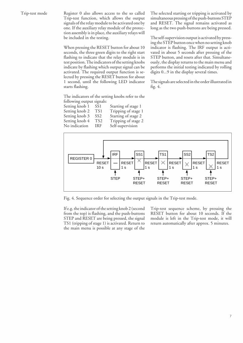
7
Trip-test mode Register 0 also allows access to the so calledTrip-test function, which allows the outputsignals of the relay module to be activated one byone. If the auxiliary relay module of the protec-tion assembly is in place, the auxiliary relays willbe included in the testing.
When pressing the RESET button for about 10seconds, the three green digits to the right startflashing to indicate that the relay module is intest position. The indicators of the setting knobsindicate by flashing which output signal can beactivated. The required output function is se-lected by pressing the RESET button for about1 second, until the following LED indicatorstarts flashing.
The indicators of the setting knobs refer to thefollowing output signals:Setting knob 1 SS1 Starting of stage 1Setting knob 2 TS1 Tripping of stage 1Setting knob 3 SS2 Starting of stage 2Setting knob 4 TS2 Tripping of stage 2No indication IRF Self-supervision
The selected starting or tripping is activated bysimultaneous pressing of the push-buttons STEPand RESET. The signal remains activated aslong as the two push-buttons are being pressed.
The self-supervision output is activated by press-ing the STEP button once when no setting knobindicator is flashing. The IRF output is acti-vated in about 5 seconds after pressing of theSTEP button, and resets after that. Simultane-ously, the display returns to the main menu andperforms the initial testing indicated by rollingdigits 0...9 in the display several times.
The signals are selected in the order illustrated infig. 4.
REGISTER 0IRF SS1 TS1 SS2 TS2
STEP STEP+RESET
STEP+RESET
STEP+RESET
STEP+RESET
RESET10 s
RESET1 s
RESET1 s
RESET1 s
RESET1 s
RESET1 s
Fig. 4. Sequence order for selecting the output signals in the Trip-test mode.
If e.g. the indicator of the setting knob 2 (secondfrom the top) is flashing, and the push-buttonsSTEP and RESET are being pressed, the signalTS1 (tripping of stage 1) is activated. Return tothe main menu is possible at any stage of the
Trip-test sequence scheme, by pressing theRESET button for about 10 seconds. If themodule is left in the Trip-test mode, it willreturn automatically after approx. 5 minutes.
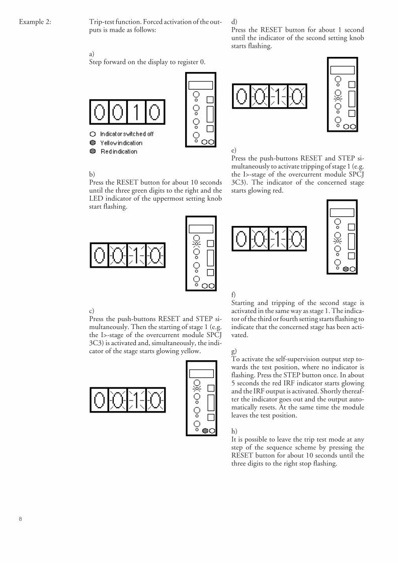
8
Example 2: Trip-test function. Forced activation of the out-puts is made as follows:
a)Step forward on the display to register 0.
b)Press the RESET button for about 10 secondsuntil the three green digits to the right and theLED indicator of the uppermost setting knobstart flashing.
c)Press the push-buttons RESET and STEP si-multaneously. Then the starting of stage 1 (e.g.the I>-stage of the overcurrent module SPCJ3C3) is activated and, simultaneously, the indi-cator of the stage starts glowing yellow.
d)Press the RESET button for about 1 seconduntil the indicator of the second setting knobstarts flashing.
e)Press the push-buttons RESET and STEP si-multaneously to activate tripping of stage 1 (e.g.the I>-stage of the overcurrent module SPCJ3C3). The indicator of the concerned stagestarts glowing red.
f)Starting and tripping of the second stage isactivated in the same way as stage 1. The indica-tor of the third or fourth setting starts flashing toindicate that the concerned stage has been acti-vated.
g)To activate the self-supervision output step to-wards the test position, where no indicator isflashing. Press the STEP button once. In about5 seconds the red IRF indicator starts glowingand the IRF output is activated. Shortly thereaf-ter the indicator goes out and the output auto-matically resets. At the same time the moduleleaves the test position.
h)It is possible to leave the trip test mode at anystep of the sequence scheme by pressing theRESET button for about 10 seconds until thethree digits to the right stop flashing.
9
Operationindicators
A measuring relay module is provided with twoseparate operating stages, each of which with itsown yellow/red operation indicator on the lowerpart of the front plate of the relay module.
The operation indicator starts glowing yellowwhen the operating stage starts and red when adelayed tripping operates. The functions of thestart and operation indicators are described indetail in the different protection relay modulemanuals.
Fault codes In addition to the protective functions the relaymodule is provided with a self-supervision sys-tem which continuously supervises the functionof the microprocessor, its program executionand the electronics.
When the self-supervision system has detected apermanent fault in the relay module, the redIRF indicator on the panel starts glowing soonafter the fault was discovered. At the same timethe module puts forward a signal to the self-supervision contact of the relay assembly.
In most fault situations a fault code, indicatingthe nature of the fault, appears on the display ofthe module. The fault code, which consists of ared digit (1) and a three digit green code number,cannot be removed from the display by reset-ting. When a fault occurs, the fault code shouldbe recorded and stated when service is ordered.

1MR
S 7
5063
9-M
UM
E
N
ABB OySubstation AutomationP.O.Box 699FIN-65101 VAASAFinlandTel. +358 (0)10 22 11Fax.+358 (0)10 22 41094www.abb.com/substationautomation