Electrical Formulae AC Three- · PDF file399 800-893-2321 Symbols & Formulae Electrical...
2
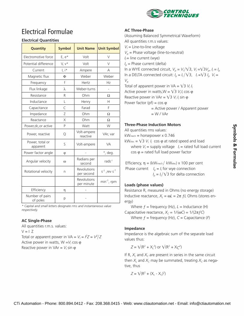
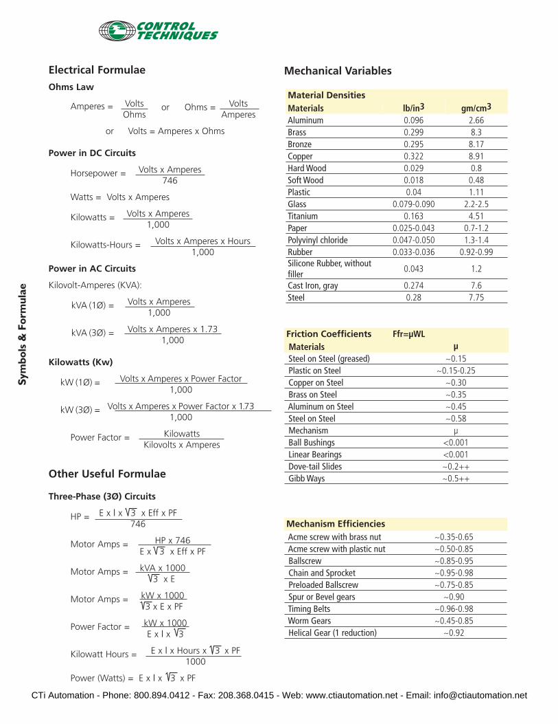
399 www.emersonct.com 800-893-2321 Symbols & Formulae Electrical Formulae Electrical Quantities Quantity Symbol Unit Name Unit Symbol Electromotive force E, e* Volt V Potential difference V, v* Volt V Current I, i* Ampere A Magnetic flux Φ Weber Weber Frequency f Hertz Hz Flux linkage λ Weber-turns - Resistance R Ohm Ω Inductance L Henry H Capacitance C Farad F Impedance Z Ohm Ω Reactance X Ohm Ω Power,dc,or active P Watt W Power, reactive Q Volt-ampere reactive VAr, var Power, total or apparent S Volt-ampere VA Power factor angle ϕ - °, deg. Angular velocity ω Radians per second rads -1 Rotational velocity n Revolutions per second s -1 ,rev s -1 Revolutions per minute min -1 , rpm Efficiency η - Number of pairs of poles p - * Capital and small letters designate rms and instantaneous value respectively. AC Single-Phase All quantities r.m.s. values: V = I Z Total or apparent power in VA = V l = I 2 Z = V 2 Z Active power in watts, W =V l cos ϕ Reactive power in VAr = V l sin ϕ AC Three-Phase (Assuming Balanced Symmetrical Waveform) All quantities r.m.s values: V l = Line-to-line voltage V p = Phase voltage (line-to-neutral) I l = line current (wye) I p = Phase current (delta) In a WYE connected circuit, V p = V l 3, V l = 3V p , I l = I p In a DELTA connected circuit: I p = I l 3, I l = 3 I p V l = V p Total of apparent power in VA = 3 V l I l Active power in watts,W = 3 V l I l cos ϕ Reactive power in VAr = 3 V l I l sin ϕ Power factor (pf) = cos ϕ = Active power / Apparent power = W / VAr Three-Phase Induction Motors All quantities rms values: kWmech = horsepower x 0.746 kWelec = 3 V l I l cos ϕ at rated speed and load where V l = supply voltage I l = rated full load current cos ϕ = rated full load power factor Efficiency, η = (kWmech kWelec) x 100 per cent Phase current I p = I l for wye connection I p = I l 3 for delta connection Loads (phase values) Resistance R, measured in Ohms (no energy storage) Inductive reactance, X L = ωL = 2π ƒL Ohms (stores en- ergy) Where ƒ = frequency (Hz), L = Inductance (H) Capacitative reactance, X C = 1/(ωC) = 1/ (2πƒC) Where ƒ = frequency (Hz), C = Capacitance (F) Impedance Impedance is the algebraic sum of the separate load values thus: Z = (R 2 + X L 2 ) or (R 2 + X C 2 ) If R, X L and X C are present in series in the same circuit then X L and X C may be summated, treating X C as nega- tive, thus Z = (R 2 + (X L - X C ) 2 ) CTi Automation - Phone: 800.894.0412 - Fax: 208.368.0415 - Web: www.ctiautomation.net - Email: [email protected]
Transcript of Electrical Formulae AC Three- · PDF file399 800-893-2321 Symbols & Formulae Electrical...
399
www.emersonct.com
800-893-2321
Symbols &
Formulae
Electrical FormulaeElectrical Quantities
Quantity Symbol Unit Name Unit Symbol
Electromotive force E, e* Volt V
Potential difference V, v* Volt V
Current I, i* Ampere A
Magnetic fl ux Φ Weber Weber
Frequency f Hertz Hz
Flux linkage λ Weber-turns -
Resistance R Ohm Ω
Inductance L Henry H
Capacitance C Farad F
Impedance Z Ohm Ω
Reactance X Ohm Ω
Power,dc,or active P Watt W
Power, reactive QVolt-ampere
reactiveVAr, var
Power, total or apparent
S Volt-ampere VA
Power factor angle ϕ - °, deg.
Angular velocity ω Radians persecond
rads-1
Rotational velocity nRevolutionsper second
s-1 ,rev s-1
Revolutionsper minute
min-1, rpm
Effi ciency η -
Number of pairsof poles
p -
* Capital and small letters designate rms and instantaneous value respectively.
AC Single-PhaseAll quantities r.m.s. values:V = I ZTotal or apparent power in VA = Vl = I2Z = V2� Z Active power in watts, W =Vl cos ϕ Reactive power in VAr = Vl sin ϕ
AC Three-Phase(Assuming Balanced Symmetrical Waveform) All quantities r.m.s values:Vl = Line-to-line voltageVp = Phase voltage (line-to-neutral) Il = line current (wye) Ip = Phase current (delta)In a WYE connected circuit, Vp = Vl ��3, Vl =�3Vp, Il = IpIn a DELTA connected circuit: Ip = Il � �3, Il =�3 Ip Vl = Vp Total of apparent power in VA = �3 Vl Il Active power in watts,W = �3 Vl Il cos ϕ Reactive power in VAr = �3 Vl Il sin ϕ Power factor (pf) = cos ϕ
= Active power / Apparent power = W / VAr
Three-Phase Induction MotorsAll quantities rms values:kWmech = horsepower x 0.746kWelec = �3 Vl Il cos ϕ at rated speed and load
where Vl = supply voltage Il = rated full load currentcos ϕ = rated full load power factor
Effi ciency, η = (kWmech � kWelec) x 100 per cent Phase current Ip = Il for wye connection
Ip = Il � �3 for delta connection
Loads (phase values)Resistance R, measured in Ohms (no energy storage) Inductive reactance, XL = ωL = 2π ƒL Ohms (stores en-ergy)
Where ƒ = frequency (Hz), L = Inductance (H) Capacitative reactance, XC = 1/ (ωC) = 1/ (2πƒC)
Where ƒ = frequency (Hz), C = Capacitance (F)
ImpedanceImpedance is the algebraic sum of the separate load values thus:
Z = �(R2 + XL2) or �(R2 + XC
2)
If R, XL and XC are present in series in the same circuit then XL and XC may be summated, treating XC as nega-tive, thus
Z = �(R2 + (XL - XC)2)
CTi Automation - Phone: 800.894.0412 - Fax: 208.368.0415 - Web: www.ctiautomation.net - Email: [email protected]
400
www.emersonct.com
800-893-2321
Sym
bols
& F
orm
ulae
Electrical Formulae
Ohms Law
Amperes = Volts or Ohms = Volts Ohms Amperes
or Volts = Amperes x Ohms
Power in DC Circuits
Horsepower = Volts x Amperes 746
Watts = Volts x Amperes
Kilowatts = Volts x Amperes 1,000
Kilowatts-Hours = Volts x Amperes x Hours 1,000
Power in AC Circuits
Kilovolt-Amperes (KVA):
kVA (1Ø) = Volts x Amperes 1,000
kVA (3Ø) = Volts x Amperes x 1.73 1,000
Kilowatts (Kw)
kW (1Ø) = Volts x Amperes x Power Factor 1,000
kW (3Ø) = Volts x Amperes x Power Factor x 1.73 1,000
Power Factor = Kilowatts Kilovolts x Amperes
Other Useful Formulae
Three-Phase (3Ø) Circuits
HP = E x I x 3 x Eff x PF 746
Motor Amps = HP x 746 E x 3 x Eff x PF
Motor Amps = kVA x 1000 3 x E
Motor Amps = kW x 1000 3 x E x PF
Power Factor = kW x 1000 E x I x 3
Kilowatt Hours = E x I x Hours x 3 x PF 1000
Power (Watts) = E x I x 3 x PF
Material DensitiesMaterials lb/in3 gm/cm3
Aluminum 0.096 2.66Brass 0.299 8.3Bronze 0.295 8.17Copper 0.322 8.91Hard Wood 0.029 0.8Soft Wood 0.018 0.48Plastic 0.04 1.11Glass 0.079-0.090 2.2-2.5Titanium 0.163 4.51Paper 0.025-0.043 0.7-1.2Polyvinyl chloride 0.047-0.050 1.3-1.4Rubber 0.033-0.036 0.92-0.99Silicone Rubber, without fi ller
0.043 1.2
Cast Iron, gray 0.274 7.6Steel 0.28 7.75
Friction Coeffi cients Ffr=µWL Materials µ Steel on Steel (greased) ~0.15 Plastic on Steel ~0.15-0.25 Copper on Steel ~0.30 Brass on Steel ~0.35 Aluminum on Steel ~0.45 Steel on Steel ~0.58 Mechanism µ Ball Bushings <0.001 Linear Bearings <0.001 Dove-tail Slides ~0.2++ Gibb Ways ~0.5++
Mechanism Effi ciencies Acme screw with brass nut ~0.35-0.65 Acme screw with plastic nut ~0.50-0.85 Ballscrew ~0.85-0.95 Chain and Sprocket ~0.95-0.98 Preloaded Ballscrew ~0.75-0.85 Spur or Bevel gears ~0.90 Timing Belts ~0.96-0.98 Worm Gears ~0.45-0.85 Helical Gear (1 reduction) ~0.92
Mechanical Variables
CTi Automation - Phone: 800.894.0412 - Fax: 208.368.0415 - Web: www.ctiautomation.net - Email: [email protected]