Design of Stator-less Turbine 28 October 2004 David Lior ...
27
1 Becker Systems Engineering Proprietary &Confidential Design of Stator-less Turbine 28 October 2004 David Lior Rafael Priampolsky
Transcript of Design of Stator-less Turbine 28 October 2004 David Lior ...
1
Becker Systems Engineering Proprietary &Confidential
Design of Stator-less Turbine
28 October 2004
David Lior
Rafael Priampolsky
2
Becker Systems Engineering Proprietary &Confidential
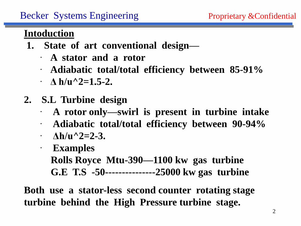
Intoduction
1. State of art conventional design—
· A stator and a rotor
· Adiabatic total/total efficiency between 85-91%
· Δ h/u^2=1.5-2.
2. S.L Turbine design
· A rotor only—swirl is present in turbine intake
· Adiabatic total/total efficiency between 90-94%
· Δh/u^2=2-3.
· Examples
Rolls Royce Mtu-390—1100 kw gas turbine
G.E T.S -50---------------25000 kw gas turbine
Both use a stator-less second counter rotating stage
turbine behind the High Pressure turbine stage.
3
Becker Systems Engineering Proprietary &Confidential
OCN S.L Turbine design
1. the inlet swirl [tangential velocity*radius ] is carried
without diffusion from the compressor rotor
through the combustor to the turbine rotor inlet
2. The inlet swirl has a small tangential angle not
attainable with conventional stator design.
3. The swirl amount may be changed by varying the
turbine design mean blade radius.
4
Becker Systems Engineering Proprietary &Confidential
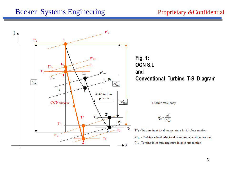
The OCN S.L Turbine t-s diagram
1. First expansion stage pure isentropic—100% efficient.
2. Second expansion stage—through rotor blades—
more efficient [see slope ] than conventional due to-
· Smaller camber angle
· Supersonic convergent blade shape.
· Higher blade length / chord ratio
· No incidence losses.
5
Becker Systems Engineering Proprietary &Confidential
Fig. 1:
OCN S.L
and
Conventional Turbine T-S Diagram
6
Becker Systems Engineering Proprietary &Confidential
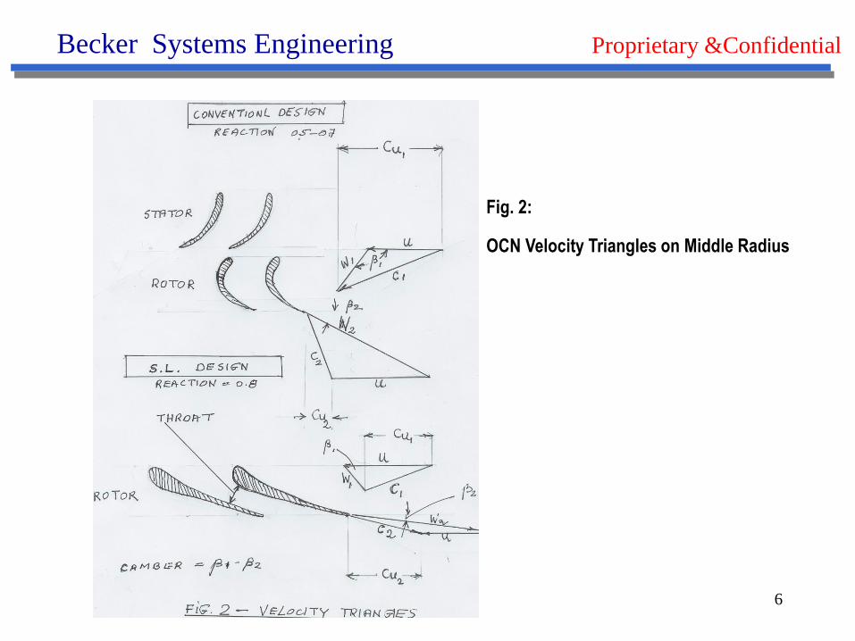
Fig. 2:
OCN Velocity Triangles on Middle Radius
7
Becker Systems Engineering Proprietary &Confidential
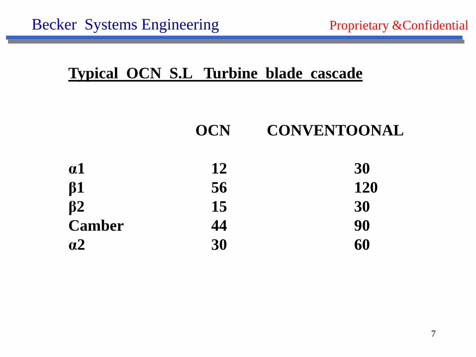
Typical OCN S.L Turbine blade cascade
OCN CONVENTOONAL
α1 12 30
β1 56 120
β2 15 30
Camber 44 90
α2 30 60
8
Becker Systems Engineering Proprietary &Confidential
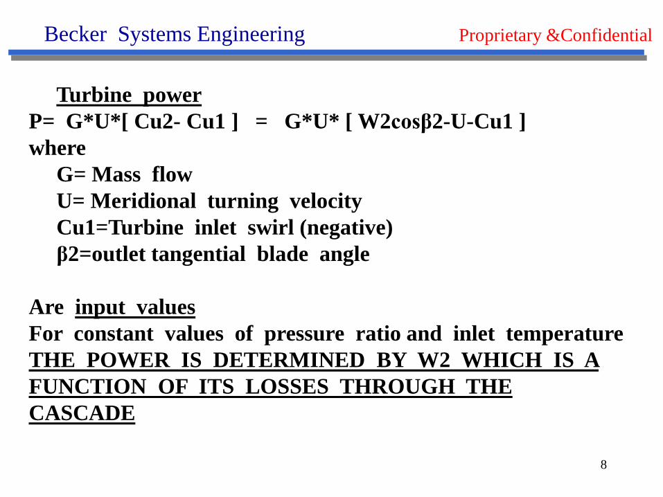
Turbine power
P= G*U*[ Cu2- Cu1 ] = G*U* [ W2cosβ2-U-Cu1 ]
where
G= Mass flow
U= Meridional turning velocity
Cu1=Turbine inlet swirl (negative)
β2=outlet tangential blade angle
Are input values
For constant values of pressure ratio and inlet temperature
THE POWER IS DETERMINED BY W2 WHICH IS A
FUNCTION OF ITS LOSSES THROUGH THE
CASCADE
9
Becker Systems Engineering Proprietary &Confidential
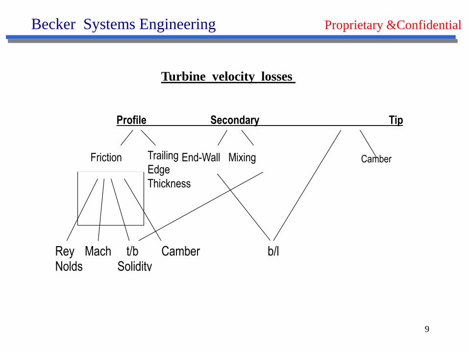
Friction End-Wall Mixing
Profile Secondary Tip
CamberTrailing
Edge
Thickness
Rey Mach t/b Camber b/l Nolds Solidity
Turbine velocity losses
10
Becker Systems Engineering Proprietary &Confidential
All above losses are expressed as the square of velocity loss/no-
loss- velocity in percentage.
The following value of
Ψ= [ 1- profile-secondary-tip ]^0.5
Determines the value of W2=W2 theoretical*ψ
Now---efficiencies may be calculated.
Turbine velocity losses - Continued
11
Becker Systems Engineering Proprietary &Confidential
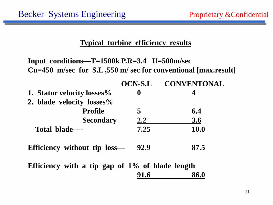
Typical turbine efficiency results
Input conditions—T=1500k P.R=3.4 U=500m/sec
Cu=450 m/sec for S.L ,550 m/ sec for conventional [max.result]
OCN-S.L CONVENTONAL
1. Stator velocity losses% 0 4
2. blade velocity losses%
Profile 5 6.4
Secondary 2.2 3.6
Total blade---- 7.25 10.0
Efficiency without tip loss— 92.9 87.5
Efficiency with a tip gap of 1% of blade length
91.6 86.0
12
Becker Systems Engineering Proprietary &Confidential
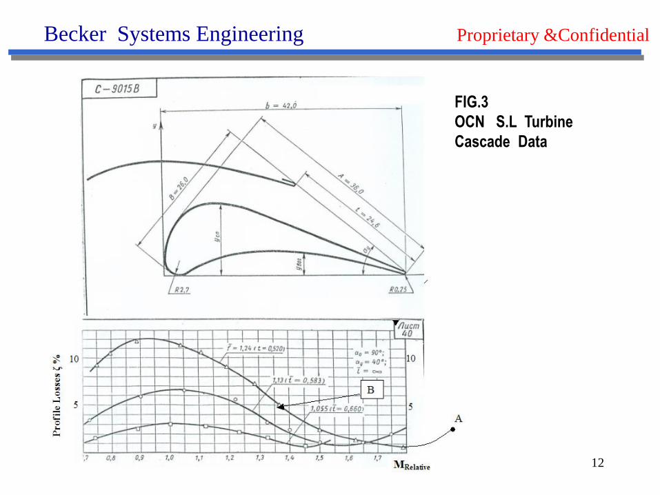
FIG.3
OCN S.L Turbine
Cascade Data
13
Becker Systems Engineering Proprietary &Confidential
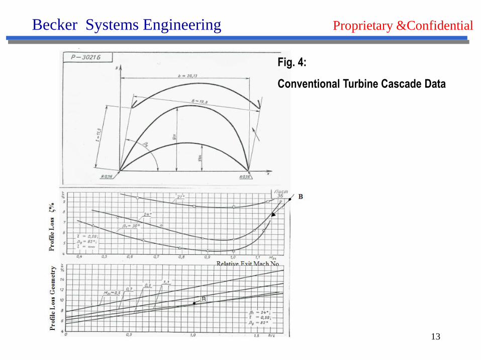
Fig. 4:
Conventional Turbine Cascade Data
14
Becker Systems Engineering Proprietary &Confidential
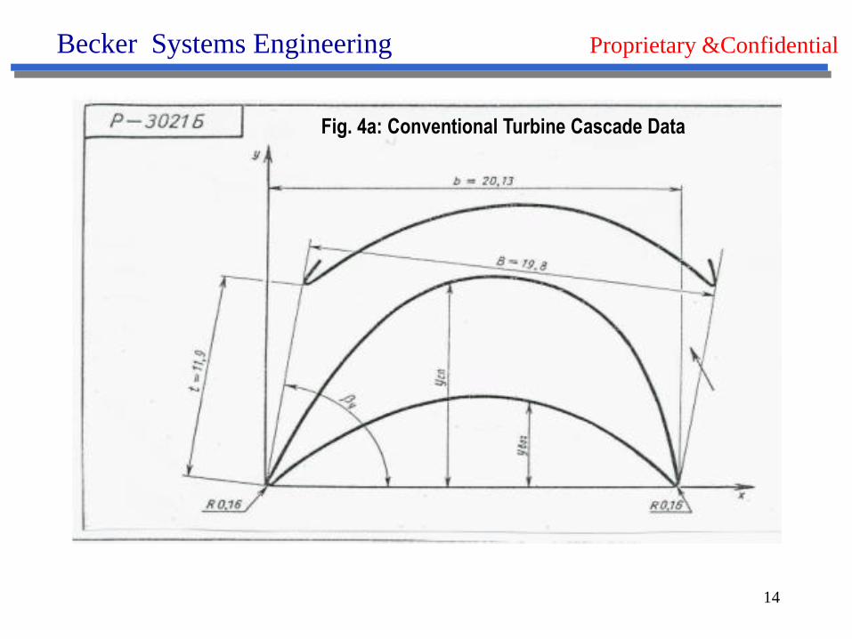
Fig. 4a: Conventional Turbine Cascade Data
15
Becker Systems Engineering Proprietary &Confidential
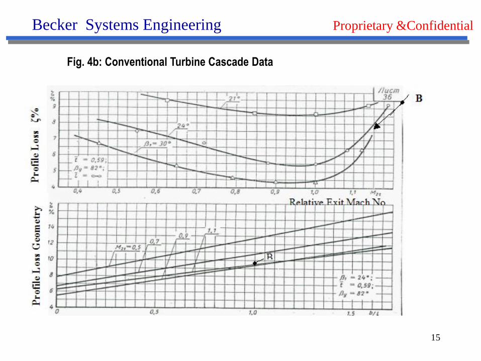
Fig. 4b: Conventional Turbine Cascade Data
16
Becker Systems Engineering Proprietary &Confidential
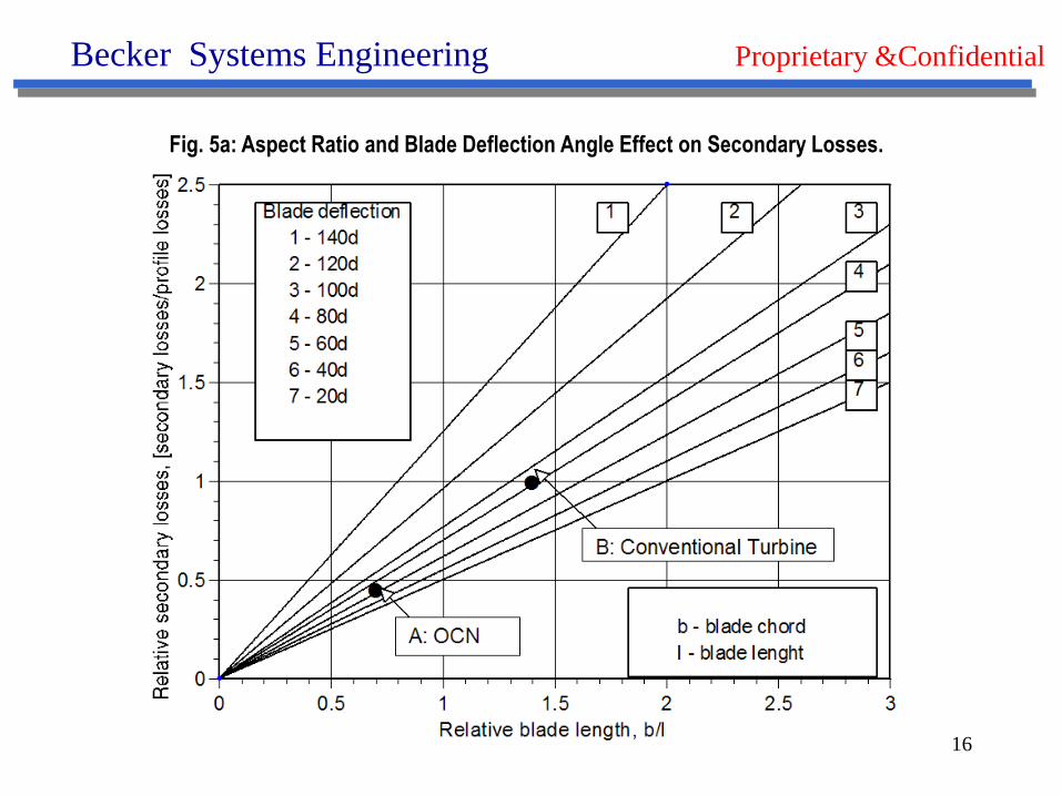
Fig. 5a: Aspect Ratio and Blade Deflection Angle Effect on Secondary Losses.
17
Becker Systems Engineering Proprietary &Confidential
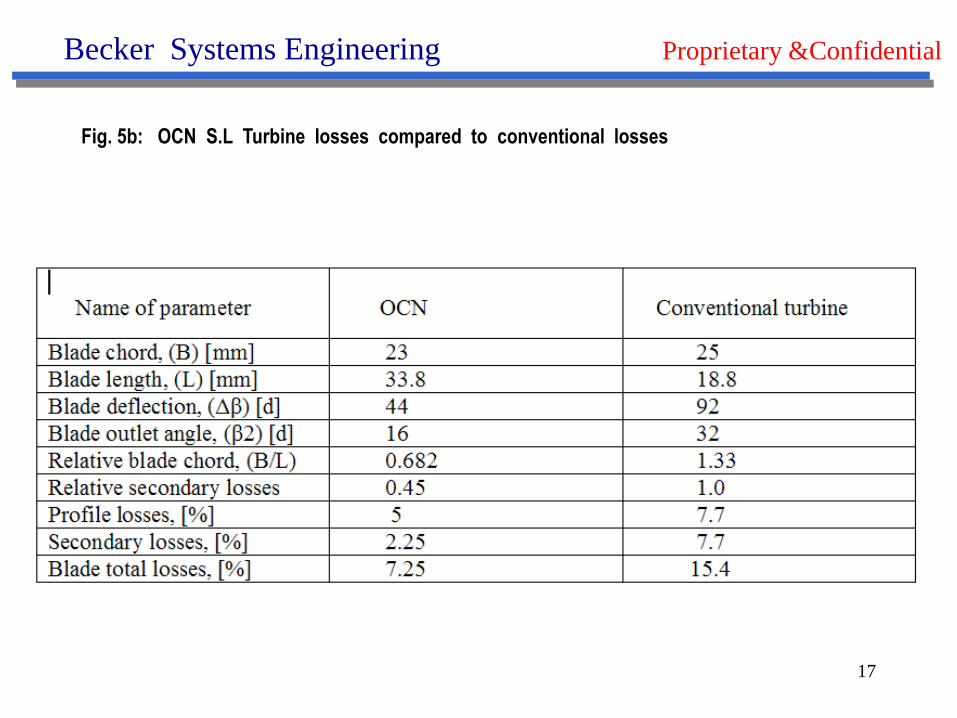
Fig. 5b: OCN S.L Turbine losses compared to conventional losses
18
Becker Systems Engineering Proprietary &Confidential
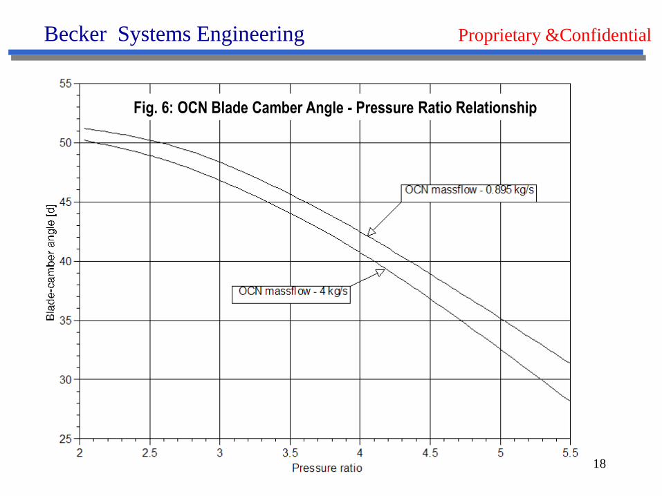
Fig. 6: OCN Blade Camber Angle - Pressure Ratio Relationship
19
Becker Systems Engineering Proprietary &Confidential
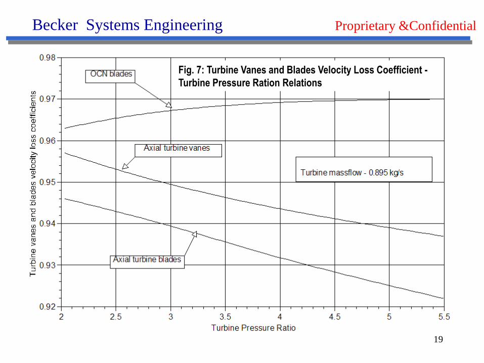
Fig. 7: Turbine Vanes and Blades Velocity Loss Coefficient -
Turbine Pressure Ration Relations
20
Becker Systems Engineering Proprietary &Confidential
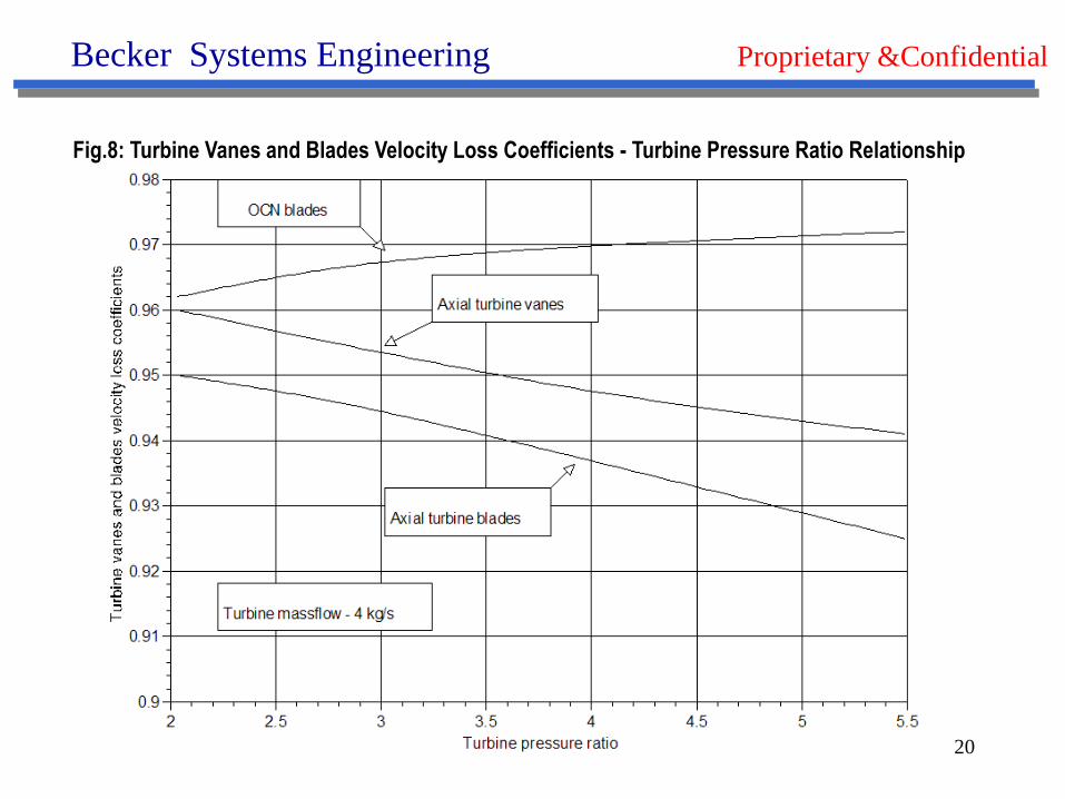
Fig.8: Turbine Vanes and Blades Velocity Loss Coefficients - Turbine Pressure Ratio Relationship
21
Becker Systems Engineering Proprietary &Confidential
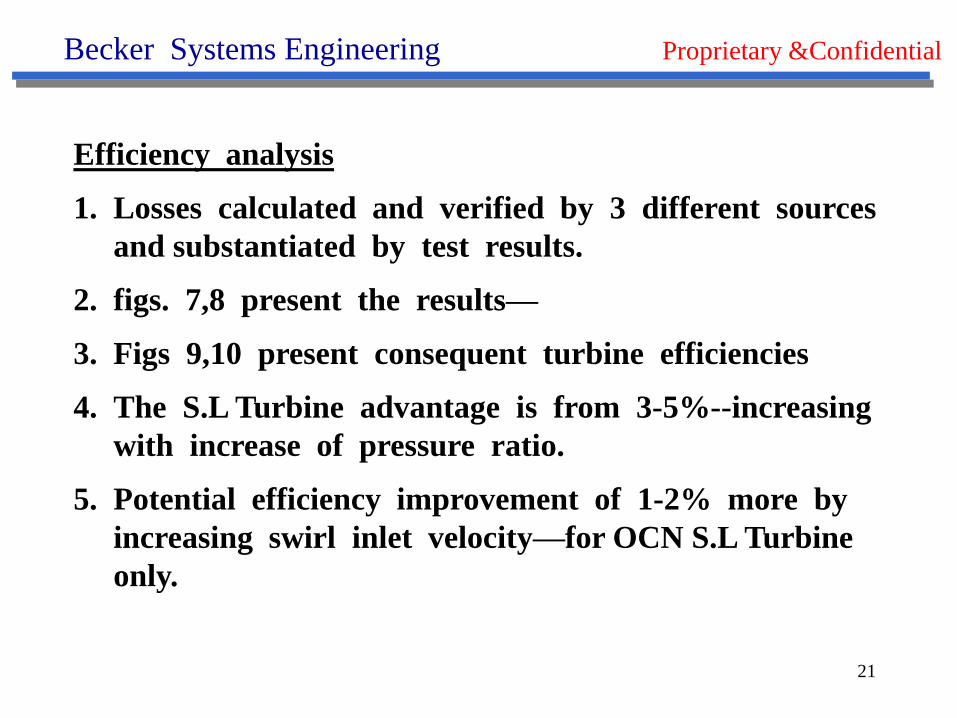
Efficiency analysis
1. Losses calculated and verified by 3 different sources
and substantiated by test results.
2. figs. 7,8 present the results—
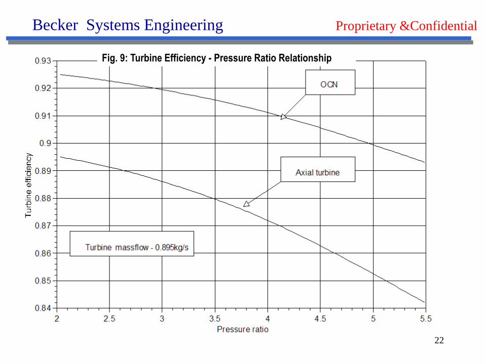
3. Figs 9,10 present consequent turbine efficiencies
4. The S.L Turbine advantage is from 3-5%--increasing
with increase of pressure ratio.
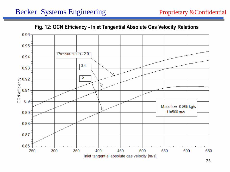
5. Potential efficiency improvement of 1-2% more by
increasing swirl inlet velocity—for OCN S.L Turbine
only.
22
Becker Systems Engineering Proprietary &Confidential
Fig. 9: Turbine Efficiency - Pressure Ratio Relationship

23
Becker Systems Engineering Proprietary &Confidential
Fig. 10: Turbine Efficiency - Pressure Ratio Relationship
24
Becker Systems Engineering Proprietary &Confidential
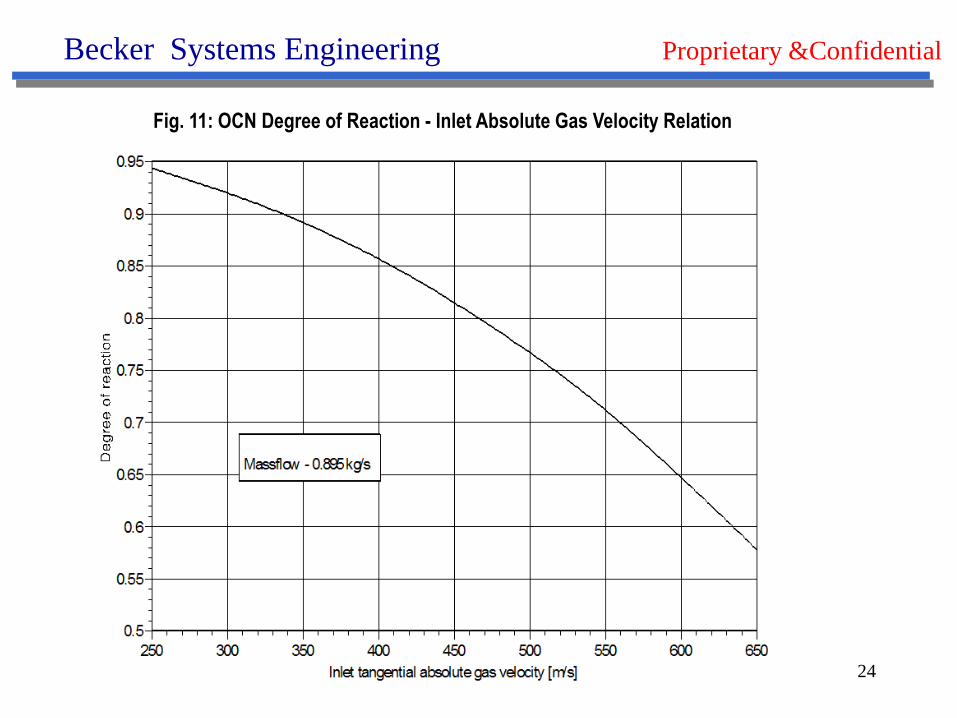
Fig. 11: OCN Degree of Reaction - Inlet Absolute Gas Velocity Relation
25
Becker Systems Engineering Proprietary &Confidential
Fig. 12: OCN Efficiency - Inlet Tangential Absolute Gas Velocity Relations
26
Becker Systems Engineering Proprietary &Confidential
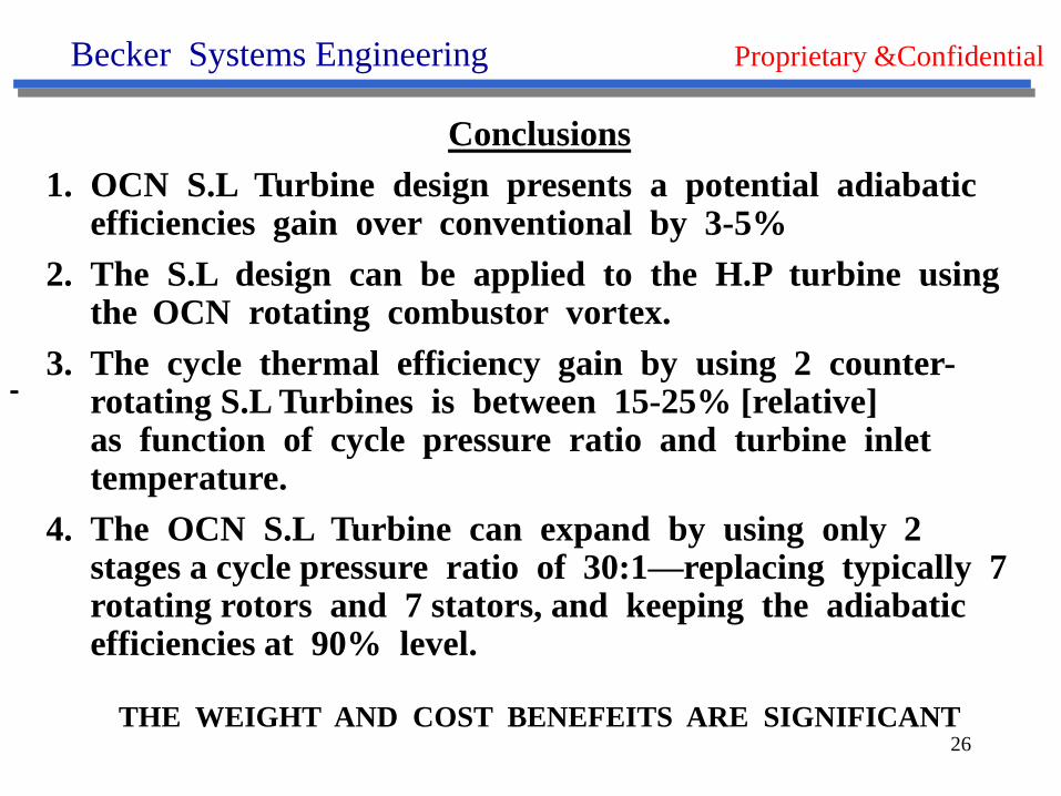
Conclusions
1. OCN S.L Turbine design presents a potential adiabatic efficiencies gain over conventional by 3-5%
2. The S.L design can be applied to the H.P turbine using the OCN rotating combustor vortex.
3. The cycle thermal efficiency gain by using 2 counter-rotating S.L Turbines is between 15-25% [relative]as function of cycle pressure ratio and turbine inlet temperature.
4. The OCN S.L Turbine can expand by using only 2 stages a cycle pressure ratio of 30:1—replacing typically 7 rotating rotors and 7 stators, and keeping the adiabatic efficiencies at 90% level.
THE WEIGHT AND COST BENEFEITS ARE SIGNIFICANT
27
Becker Systems Engineering Proprietary &Confidential
Thank You For Your Patience