Curtis 1206MX - FSIP PDS with 1206MX Control.pdfEZGO PDS (Curtis 1206MX) DIAGNOSTICS STEPS TO...
4
Sheet 1 of 4 77-E-Z-GO PDS (1206MX) Install Sheet-370 Rev 02 11/29/2018 CHECK MOTOR WINDINGS: Set your VOM to RESISTANCE (Ω). With your motor disconnected, measure A1 to A2. This must measure BETWEEN .3Ω and 1Ω. With your motor disconnected, measure F1 to F2. This must measure BETWEEN 1Ω and 2Ω. With your motor disconnected, measure A1 to F1. This must measure OPEN. With your motor disconnected, measure F1 to motor case. This must measure greater than 5MΩ. CHECK MAIN SOLENOID: Disconnect all wires from the main solenoid. Set your VOM to RESISTANCE (Ω). Measure the solenoid coil. This must measure NO LESS than 100Ω. Connect VOM leads to the main solenoid lugs. Attach jumpers from the main battery positive and negative to the coil (small terminals). Meter must jump from infinity to LESS THAN .3Ω. Remove jumpers and reconnect solenoid wiring from the harness. (If suppression diode is present, The non-banded side must go the blue wire – pin J1-6 from the controller.) CHECK COTHERM: Inspect the cotherm (insulating material) mounted to the heat sink for holes, debris, and tears. Repair or replace, if necessary. CHECK THE CART WIRE HARNESS: Check the connectors on the wire harness for corrosion, loose, broken, burnt or missing pins. Repair or replace pins as necessary. STEPS TO PERFORM BEFORE CONTROL INSTALLATION Curtis 1206MX This sheet is provided to aid in the installation of your remanufactured CURTIS controller. Upon installation, you may encounter problems that may, or may not, be due to a faulty controller. The following steps must be taken to help diagnose a possible cart fault or faulty controller. An analog or digital volt ohm meter (VOM) will be needed to perform these checks. WARRANTY WILL BE VOID If These Steps are Not Performed Before Installing The Control IF ANY OF THE ABOVE ITEMS ARE NOT WITHIN THE SPECIFICED RANGES THE CONTROLLER WILL FAIL. THESE ITEMS MUST BE CORRECTED BEFORE THE CONTROLLER IS INSTALLED OR WARRANTY WILL BE VOID. It is recommended to replace your solenoid at the time of controller replacement. FSIP now stocks popular replacement White Rodgers solenoids for your convenience.
Transcript of Curtis 1206MX - FSIP PDS with 1206MX Control.pdfEZGO PDS (Curtis 1206MX) DIAGNOSTICS STEPS TO...
Sheet 1 of 4 77-E-Z-GO PDS (1206MX) Install Sheet-370 Rev 02 11/29/2018
CHECK MOTOR WINDINGS:
Set your VOM to RESISTANCE (Ω).
With your motor disconnected, measure A1 to A2. This must measure BETWEEN .3Ω and 1Ω.
With your motor disconnected, measure F1 to F2. This must measure BETWEEN 1Ω and 2Ω.
With your motor disconnected, measure A1 to F1. This must measure OPEN.
With your motor disconnected, measure F1 to motor case. This must measure greater than 5MΩ.
CHECK MAIN SOLENOID:
Disconnect all wires from the main solenoid.
Set your VOM to RESISTANCE (Ω).
Measure the solenoid coil. This must measure NO LESS than 100Ω.
Connect VOM leads to the main solenoid lugs.
Attach jumpers from the main battery positive and negative to the coil (small terminals).
Meter must jump from infinity to LESS THAN .3Ω.
Remove jumpers and reconnect solenoid wiring from the harness. (If suppression diode is present, The non-banded side must go the blue wire – pin J1-6 from the controller.)
CHECK COTHERM:
Inspect the cotherm (insulating material) mounted to the heat sink for holes, debris, and tears.
Repair or replace, if necessary.
CHECK THE CART WIRE HARNESS:
Check the connectors on the wire harness for corrosion, loose, broken, burnt or missing pins.
Repair or replace pins as necessary.
EZGO PDS (Curtis 1206MX) DIAGNOSTICS
STEPS TO PERFORM BEFORE CONTROL INSTALLATION
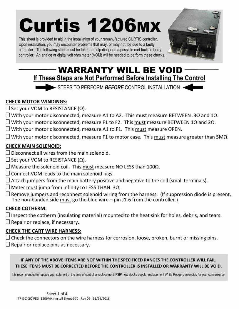
Curtis 1206MX This sheet is provided to aid in the installation of your remanufactured CURTIS controller.
Upon installation, you may encounter problems that may, or may not, be due to a faulty
controller. The following steps must be taken to help diagnose a possible cart fault or faulty
controller. An analog or digital volt ohm meter (VOM) will be needed to perform these checks.
WARRANTY WILL BE VOID If These Steps are Not Performed Before Installing The Control
IF ANY OF THE ABOVE ITEMS ARE NOT WITHIN THE SPECIFICED RANGES THE CONTROLLER WILL FAIL.
THESE ITEMS MUST BE CORRECTED BEFORE THE CONTROLLER IS INSTALLED OR WARRANTY WILL BE VOID.
It is recommended to replace your solenoid at the time of controller replacement. FSIP now stocks popular replacement White Rodgers solenoids for your convenience.
Sheet 2 of 4 77-E-Z-GO PDS (1206MX) Install Sheet-370 Rev 02 11/29/2018
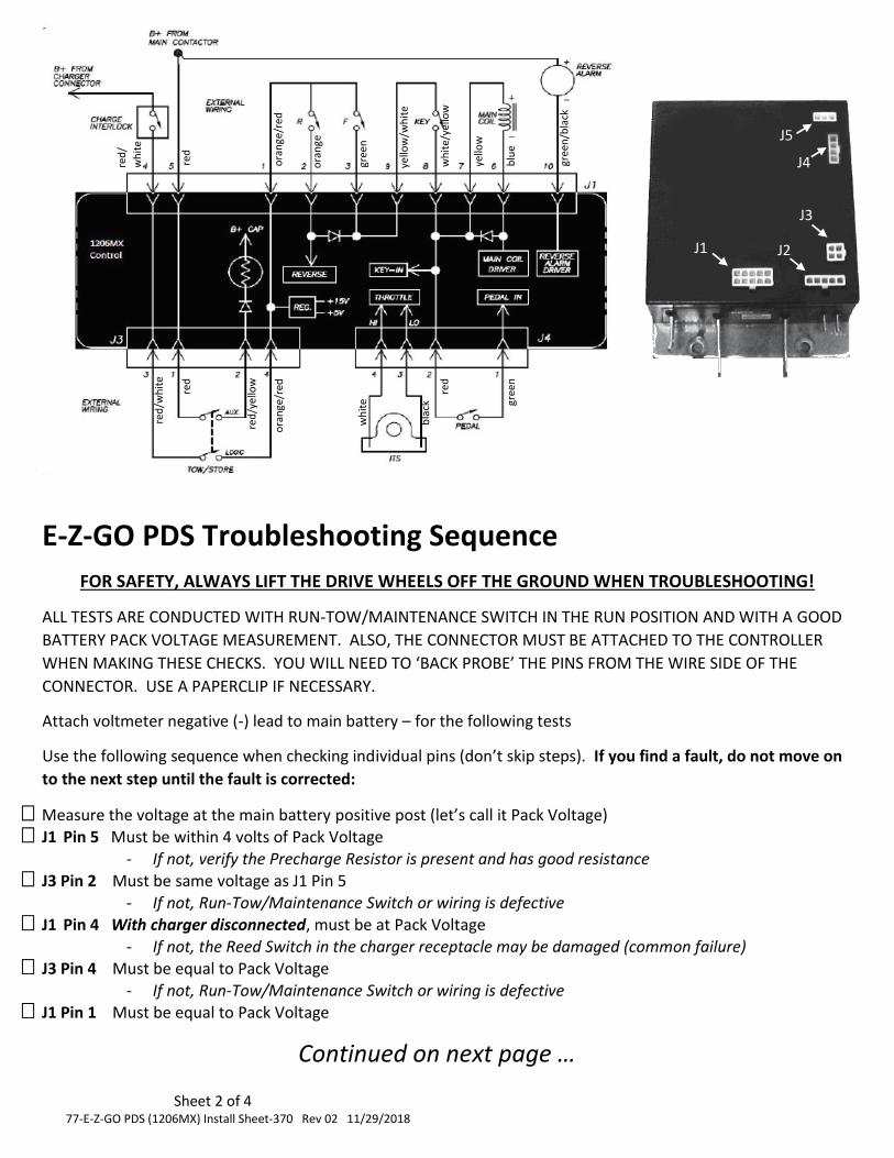
E-Z-GO PDS Troubleshooting Sequence
FOR SAFETY, ALWAYS LIFT THE DRIVE WHEELS OFF THE GROUND WHEN TROUBLESHOOTING!
ALL TESTS ARE CONDUCTED WITH RUN-TOW/MAINTENANCE SWITCH IN THE RUN POSITION AND WITH A GOOD
BATTERY PACK VOLTAGE MEASUREMENT. ALSO, THE CONNECTOR MUST BE ATTACHED TO THE CONTROLLER
WHEN MAKING THESE CHECKS. YOU WILL NEED TO ‘BACK PROBE’ THE PINS FROM THE WIRE SIDE OF THE
CONNECTOR. USE A PAPERCLIP IF NECESSARY.
Attach voltmeter negative (-) lead to main battery – for the following tests
Use the following sequence when checking individual pins (don’t skip steps). If you find a fault, do not move on
to the next step until the fault is corrected:
Measure the voltage at the main battery positive post (let’s call it Pack Voltage) J1 Pin 5 Must be within 4 volts of Pack Voltage
- If not, verify the Precharge Resistor is present and has good resistance
J3 Pin 2 Must be same voltage as J1 Pin 5 - If not, Run-Tow/Maintenance Switch or wiring is defective
J1 Pin 4 With charger disconnected, must be at Pack Voltage - If not, the Reed Switch in the charger receptacle may be damaged (common failure)
J3 Pin 4 Must be equal to Pack Voltage - If not, Run-Tow/Maintenance Switch or wiring is defective
J1 Pin 1 Must be equal to Pack Voltage
Continued on next page …
J1 J2
J3
J4
J5
gree
n/b
lack
blu
e
yello
w
wh
ite/
yello
w
gree
n
ora
nge
ora
nge
/red
yello
w/w
hit
e
red
red
/
wh
ite
red
/wh
ite
red
red
/yel
low
ora
nge
/red
red
gree
n
wh
ite
bla
ck
Sheet 3 of 4 77-E-Z-GO PDS (1206MX) Install Sheet-370 Rev 02 11/29/2018
J1 Pin 2 With F/R Switch to Neutral, must be approximately 0 volts - If not, check wiring, F/R switch for shorted condition
J1 Pin 2 With F/R Switch to Reverse, must be equal to Pack Voltage - If not, check wiring, F/R switch for open condition
J1 Pin 3 With F/R Switch to Neutral, must be approximately 0 volts - If not, check wiring, F/R switch for shorted condition
J1 Pin 3 With F/R Switch to Forward, must be equal to Pack Voltage - If not, check wiring, F/R switch for open condition
J1 Pin 9 With F/R Switch to Forward or reverse, must be equal to Pack Voltage - If not, check wiring or connector for contamination
J1 Pin 8 With Key Off, must be equal to approximately 0 volts - If not, check Key Switch for shorted condition
J1 Pin 8 With Key On, must be equal to approximately Pack Voltage - If not, check Key Switch for open condition
J1 Pin 7 Must be equal to approximately Pack Voltage
- If not, check wiring or connector for contamination
J1 Pin 6 Must be equal to Pack Voltage - If not, check wiring, and solenoid for open condition
J1 Pin 10 With F/R Switch to Neutral, must be Pack Voltage - If not, check wiring or backup beeper for an open or missing condition
J1 Pin 10 With F/R Switch to Reverse, must pulse to approximately 0 volts (should hear beeper) - If not, check wiring or backup beeper for open condition
J4 Pin 2 Must be equal to Pack Voltage - If not, check wiring or connector for contamination
J4 Pin 1 With Pedal not depressed, must be equal to approximately 0 volts - If not, check wiring and Pedal Switch for shorted condition
J4 Pin 1 With Pedal fully depressed, must be equal to Pack Voltage
- If not, check wiring and Pedal Switch for open condition J4 Pin 4 Must be between 13 and 16 volts
- If not, remove ITS Sensor and measure again. If voltage increases to 13 to 16 volts with sensor removed, replace ITS Sensor
J4 Pin 3 With Pedal not depressed, must be approximately .5 to .9 volts - If not, check wiring. If wiring is good, issue may be with ITS Sensor
J4 Pin 3 With Pedal fully depressed, must be approximately 2.5 to 3.3 volts - Voltages significantly outside of the .9 to 3.3 volt range may indicate an issue with the ITS Sensor.
Replace as necessary. J5 Pin 3 Must be between 12 and 15 volts
- If not, remove Speed Sensor and measure again. If voltage increases to 12 to 15 volts with sensor
removed, replace Speed Sensor J5 Pin 2 With drive wheels off the ground, s-l-o-w-l-y turn the drive wheel by hand. Your meter should toggle between approximately 0 and 5 volts
- If not toggling, check the motor magnet. If the magnet is cracked/damaged, replace magnet and recheck. If magnet is good, Speed Sensor or wiring is at fault.
Continued on next page …
-
Sheet 4 of 4 77-E-Z-GO PDS (1206MX) Install Sheet-370 Rev 02 11/29/2018
Helpful Hints
DO NOT UNDER ESTIMATE THE IMPORTANCE OF MOTOR RESISTANCE CHECKS AND MAIN SOLENOID CHECKS.
MANY CART ISSUES ARE CAUSED BY BURNT/DAMAGED BRUSHES THAT WILL BE FOUND AS PART OF THE
ARMATURE RESISTANCE CHECK. ALSO A SHORTED ARMATURE AND FIELD WITHIN THE MOTOR WILL DAMAGE
THIS CONTROLLER.
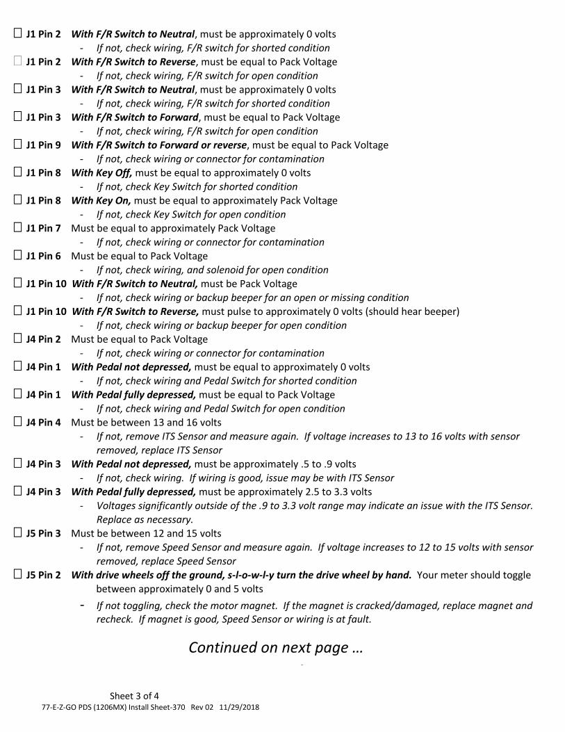
This cart is capable of diagnostics! Placing the cart in the
diagnostics mode will allow the controller to use the back-up
alarm to beep out codes. Do not under estimate the usefulness
of this tool. There is an orange and white sticker on the
environmental cover that explains how to enter the diagnostics
mode. For example, if your cart is traveling slow, and you enter
diagnostics mode and it beeps the following sequence …
<beep> <short pause> <beep> <beep> <beep> <long pause> <repeat>
That would represent a 1,3 code or Speed Sensor fault.
If your label is missing or illegible, you can visit our website for
a copy of the information. Just visit the page below …
http://www.fsip.biz/Documents/EZGO%20PDS%20Diagnostics.pdf
to
PR
E-IN
ST
AL
LA
TIO
N
INS
TR
UC
TIO
NS
MU
ST
BE
FO
LL
OW
ED
OR
WA
RR
AN
TY
WIL
L B
E V
OID
IMP
OR
TA
NT
! E-Z
-GO
PD
S
TR
OU
BL
ES
HO
OT
ING
INF
OR
MA
TIO
N
INC
LU
DE
D IN
TH
IS P
AC
KE
T
Flight Systems Industrial Products also offers the
following Technical Support options …
Troubleshooting Manuals / Codes www.fsip.biz/TroubleshootingManuals.html
Technical Support Forum Fsip.websitetoolbox.com
Frequently Asked Questions www.fsip.biz/FAQ.html
Phone Support
1-800-333-1194