
Course No: E04-034 Credit: 4 PDH - CED Engineering Protection.pdfCourse No: E04-034 Credit: 4 PDH...
35
Distance Protection Course No: E04-034 Credit: 4 PDH Velimir Lackovic, Char. Eng. Continuing Education and Development, Inc. 9 Greyridge Farm Court Stony Point, NY 10980 P: (877) 322-5800 F: (877) 322-4774 [email protected]
Transcript of Course No: E04-034 Credit: 4 PDH - CED Engineering Protection.pdfCourse No: E04-034 Credit: 4 PDH...

Distance Protection Course No: E04-034
Credit: 4 PDH
Velimir Lackovic, Char. Eng.
Continuing Education and Development, Inc. 9 Greyridge Farm Court Stony Point, NY 10980 P: (877) 322-5800 F: (877) 322-4774 [email protected]

DISTANCE PROTECTION
Combination of fast fault clearance with selective operation of protection element is
the main objective for the protection of electrical power systems. To reach these
demands, high-speed protection arrangements for electric transmission and
distribution networks that are appropriate for use with the automatic reclosure of circuit
breakers are under constant research. Distance protection, is a non-unit protection
arrangement providing significant financial and technical benefits. Unlike phase and
neutral overcurrent protection arrangements, the key benefit of distance protection is
that its short circuit current coverage of the protected element is almost autonomous
of source impedance changes. This principle is shown in Figure 1. It can be noted that
overcurrent protection cannot be used satisfactorily.
√14113 - Relay R1 setting > 14113 A
√12702 - Relay R1 setting > 12702 A
Figure 1. Benefits of distance over overcurrent protection (Relay current setting
<12702 A and >14113 A. This is not practical, overcurrent protection relay not
appropriate. Distance or unit protection is preferred.
220 kV
ZS=10Ω
I>>
Z1=4Ω
F1
ZS=10Ω
R1
220 kV I>>
Z1=4Ω
F2
ZS=10Ω
R1

Distance protection is relatively simple to use and it can be quick in service for short
circuits happening along most of protected elements. It can also provide primary and
remote back-up functions in a single operating arrangement. It can simply be adjusted
to make a unit protection arrangement when used with a communication link. In this
arrangement it is eminently applicable for usage with high-speed auto-reclosing, for
the protection of major transmission circuits.
DISTANCE RELAY FOUNDATIONS
Since the impedance of a transmission circuit is relative to its length, for distance
measure it is suitable to use a relay able to measure the impedance of a circuit up to
a present point (the reach point). Such a protection relay is known as a distance
protection relay and is made to function only for faults happening between the
protection relay location and the chosen reach point, therefore providing discrimination
for short circuits that may happen in different line portions.
The fundamental rule of distance protection includes the division of the voltage at the
relaying point by the measured current. The calculated impedance is equated with the
reach point impedance. In the case the measured impedance is lower than the reach
point impedance, it is presumed that a fault is on the circuits between the relay and
the reach point. The reach point of a protection relay is the point along the transmission
line impedance locus that is crossed by the boundary feature of the protection relay.
Since this depends on the ratio of voltage and current and the phase angle between
them, it may be shown on an R/X graph. The loci of electrical power system
impedances as detected by the protection relay during faults, power swings and load
changes may be shown on the same graph. The service of the protection relay in the
presence of electrical system faults and disturbances may be examined, using this
method.
RELAY OPERATION
Distance protection relay operation is expressed in terms of reach exactness and
operating time. Reach exactness is a comparison of the real ohmic reach of the
protection relay under real circumstances with the protection relay setting value in
ohms. Reach exactness is especially dependant on the level of voltage shown to the
protection relay under fault period. The impedance measuring methodologies used in
special relay arrangement also have an influence.
Functioning times can change with short circuit current, with short circuit position
relative to the protection relay setting, and with the point on the voltage wave at which
the short circuit happens. Depending on the measuring processes used in a specific
relay arrangement, measuring signal transient errors, such as those made by
capacitor voltage transformers or saturating CTs, can adversely slow relay function for
short circuit currents close to the reach point. It is typical for electromechanical and
static distance protection relays to claim both maximum and minimum functioning
times. Nevertheless, for modern digital or numerical distance protection relays, the
change between these is negligible over a wide range of electrical system operating
states and fault locations.
ELECTROMECHANICAL/STATIC DISTANCE PROTECTION RELAYS
With electromechanical and static protection relay arrangements, the magnitude of
input quantities is determined by both reach exactness and functioning time. It was
accustomed to show data on relay operation by voltage/reach curves, as presented in
Figure 2, and servicing time/fault location curves for different values of electrical
system impedance ratios (S.I.R.s) as presented in Figure 3, where:
. .
And ZS – electrical system source impedance behind the relay points ZL – electrical line impedance equivalent to protection relay reach setting

Figure 2. Common impedance reach exactness characteristics for Zone 1
97
98
99
100
101
102
103
104
105
0 20 40 60
Imp
edan
ce r
each
(%
Zo
ne
1 se
ttin
g)
% relay rated voltage - Phase-earth faults
95
96
97
98
99
100
101
102
103
104
105
0 20 40 60 80 100
Imp
edan
ce r
each
(%
Zo
ne
1 se
ttin
g)
% relay rated voltage - Phase - phase faults
95
96
97
98
99
100
101
102
103
104
105
0 20 40 60 80 100
Imp
edan
ce r
each
(%
Zo
ne
1 se
ttin
g)
% relay rated voltage - Three phase and three phase earth faults

Figure 3. Common functioning time characteristics for Zone 1 line-line faults
Instead the above data was mixed in a family of contour curves, where the short circuit
current location given as a percentage of the protection relay setting is presented
against the source to line impedance ratio, as shown in Figure 4.
0
5
10
15
20
25
30
35
40
45
50
0 20 40 60 80 100
Op
era
tio
n t
ime
(m
s)
Fault position (% realy setting) - System impedance ratio 1/1
Min Max
05
101520253035404550
0 20 40 60 80 100
Op
era
tio
n t
ime
(ms)
Fault position (% realy setting) - System impedance ratio 30/1
Min Max

Figure 4. Common function-time contours (a) Zone 1 line-line fault: minimum
performance times (b) Zone 1 line-line fault: maximum performance times
DIGITAL/NUMERICAL DISTANCE PROTECTION RELAYS
Digital/Numerical distance protection relays usually have more coherent performance
times. The best transmission-class protection relays can reach sub-cycle functioning,
and the available digital filtering processes guarantee optimum service under adverse
waveform circumstances or for boundary fault conditions.
RELATIONSHIP BETWEEN RELAY VOLTAGE AND ZS/ZL RATIO
A unique, generic, equivalent circuit, as presented in Figure 5, may correspond to any
0
0.2
0.4
0.6
0.8
1
1.2
0.01 0.1 1 10 100Fau
lt p
osi
tio
n (
p.u
. rel
ay s
etti
ng
Z
L)
ZS/ZL or S.I.R.
9 ms 13 ms Boundary
0
0.2
0.4
0.6
0.8
1
1.2
0.01 0.1 1 10 100Fau
lt p
osi
tio
n (
p.u
. rel
ay s
etti
ng
Z
L)
ZS/ZL or S.I.R.
15 ms 20 ms Boundary

short circuit current condition in a three-phase electrical power system. The voltage V
enforced to the impedance loop is the open circuit voltage of the electrical power
system. Point R corresponds to the relay position; IR and VR are the current and voltage
sensed by the relay.
The impedances Zs and ZL are depicted as source and transmission line impedances
because of their location in relation to the relay location. Source impedance Zs is a
quantity of the short circuit current level at the relaying location. For short circuit
currents involving ground it is dependent on the technique of electrical system
grounding behind the relaying location. Line impedance ZL is a quantity of the
impedance of the protected region. The voltage VR utilized to the protection relay is,
hence, IRZL. For a short circuit current at the reach point, this may be instead conveyed
in terms of source to transmission line impedance ratio ZS/ZL applying the following
equation:
Where
Hence,
Or
V V (1)
Line Source
V
VS
ZS ZL VR
VL IR
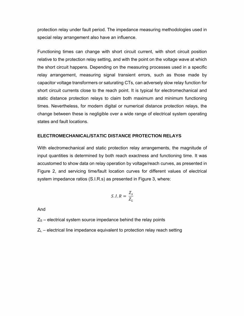
Figure 5. Link between source to transmission line ratio and protection relay voltage
(a) Electrical power system arrangement (b) Change of protection relay voltage with
electrical system source to transmission line impedance ratio
The above universal relationship between VR and ZS/ZL, presented in Figure 5, is true
for all cases of short circuit currents given a few elementary rules are kept. These rules
are:
- For line faults, V∆ is the line-line source voltage and ZS/ZL is the positive
sequence source to transmission line impedance ratio. VR is the line-line
protection relay voltage and IR is the line-line protection relay current, for the
faulted lines
V V∆ (2)
- For ground short circuit currents, Vl-n is the line-neutral source voltage and
ZS/ZL, is a composite ratio taking the positive and zero sequence impedances.
VR is the line-neutral protection relay voltage and IR is the protection relay
current for the faulted line
V V (3)
Where:
0
10
20
30
40
50
60
70
80
90
100
0.1 1 10
Vlt
age
VR
(% r
ate
d v
olt
age
)
System impedance ratio ZS/ZL
2 2
2 2 And
VOLTAGE LIMIT FOR PRECISE REACH POINT MEASUREMENT
The power of a distance protection relay to precisely assess reach point fault is
dependent on the minimum voltage at the protection relay position under this
condition. This voltage, that is dependent on the protection relay arrangement, can
also be expressed in terms of an equivalent maximum ZS/ZL or S.I.R. Distance
protection relays are made so that, given the reach point voltage standard is reached,
any increased measuring errors for short circuits closer to the protection relay will not
stop protection relay performance. Most protection relays are manufactured with
healthy line voltage polarisation and/or memory voltage polarisation. The prime use of
the protection relay polarizing voltage is to make sure correct protection relay
directional response for close-up short circuit currents, in the forward or reverse
direction, where the fault-loop voltage sensed by the protection relay may be very low.
DISTANCE PROTECTION ZONES
Careful choice of the reach settings and operation times for the different zones of
measurement allows proper coordination between distance protection relays on an
electric power system. Fundamental distance protection will contain instantaneous
directional Zone 1 relay protection and one or more time-delayed zones. Common
reach and time settings for a 3-zone distance relay protection are presented in Figure
6. Digital and numerical distance protection relays may have up to five or six protection
zones, some set to sense in the reverse direction. Common settings for three forward-
looking zones of basic distance relay protection are shown in the following paragraphs.
To find out the settings for a specific protection relay arrangement or for a specific
distance tele-protection arrangement, involving end-to-end signalling, the protection
relay producer’s suggestions and manuals should be consulted.
ZONE 1 PROTECTION SETTING
Electromechanical/static protection relays typically have a reach setting of up to 80%
of the protected transmission line impedance for instantaneous Zone 1 protection. For
digital/numerical distance protection relays, settings of up to 85% may be adequate.
The obtained 15-20% safety margin assures that there is no possibility of the Zone 1
protection over-reaching the protected transmission circuit due to errors in the current
and voltage transformers, inaccuracies in transmission line impedance information
given for setting needs and errors of protection relay setting and measurement.
Otherwise, there would be improper discrimination with fast functioning relay
protection on the following transmission line section. Zone 2 of the distance relay
protection has to cover the remaining 15-20% of the transmission line.
ZONE 2 PROTECTION SETTING
To assure complete coverage of the transmission line with provision for the sources
of error already presented in the previous paragraph, the reach protection setting of
the Zone 2 protection need to be at least 120% of the protected transmission line
impedance. In many usages it is typical practice to set the Zone 2 reach to be same
to the protected transmission line section +50% of the shortest adjacent transmission
line. Where feasible, this assures that the ending maximum effective protection Zone
2 reach does not goes beyond the minimum effective protection Zone 1 reach of the
adjacent transmission line protection. This eliminates the requirement to grade the
protection Zone 2 time settings between upstream and downstream protection relays.
In electromechanical and static protection relays, Zone 2 protection is given either by
different elements or by extending the protection reach of the Zone 1 devices after a
time delay that is started by a fault detector. In majority of digital and numerical
protection relays, the Zone 2 devices are put in software.
Zone 2 tripping has to be time-delayed to assure grading with the primary protection
relaying used to adjacent transmission circuits that fall within the Zone 2 protection
reach. Hence, full coverage of a transmission line portion is achieved, with fast
clearance of short circuits in the first 80-85% of the transmission line and reasonably
slower short circuit current clearance in the remaining portions of the transmission
circuit.

Figure 6. Common time/distance characteristics for three zone distance relay
protection
ZONE 3 PROTECTION SETTING
Remote back-up relay protection for all short circuit currents on adjacent transmission
lines can be given by a third zone of relay protection that is time delayed to discriminate
with Zone 2 relay protection plus circuit breaker operation time for the adjacent
transmission line. Protection Zone 3 reach should be adjusted to at least 1.2 times the
impedance given to the protection relay for a short circuit at the remote end of the
second transmission line portion. On interconnected electrical power systems, the
impact of short circuit current infeed at the remote bus will create the impedance
shown to the protection relay to be much higher than the actual impedance to the short
circuit and this has to be considered when setting protection Zone 3. In some electrical
systems, differences in the remote bus infeed can prohibit the usage of remote back-
up protection Zone 3 but on radial distribution electrical systems with single end infeed,
there should not be problems.
Zone 1 =80-85% of protected transmission line impedance
Zone 2 (minimum)=120% of protected transmission line
Zone 2 (maximum)<Protected transmission line+50% of shortest second transmission line
Zone 3F=1.2 (protected transmission line +longest second transmission line)
Zone 3R=20% of protected transmission line
X= Circuit breaker tripping time
Y= Discriminating time
X
Y X
Z3JR Z3JF
Z2J
Z1J Z1L
Time
Source Source
H J K L
Time
0
Z1H Z1K
Z2K
Z3K Z3KR
Y
PROTECTION SETTINGS FOR REVERSE REACH AND OTHER ZONES
Modern digital or numerical protection relays may have extra impedance zones that
can be used to give extra protection functions. For instance, where the first three
protection zones are set as above, Zone 4 could be used to give back-up protection
for the local bus, by using a reverse reach setting of the order of 25% of the protection
Zone 1 reach. Also, one of the forward-looking protection zones (usually Zone 3) could
be adjusted with a low reverse offset reach from the origin of the R/X graph, in addition
to its forward reach setting. An offset impedance measurement characteristic is non-
directional. One benefit of a non-directional protection zone of impedance
measurement is that it is capable to function for a close-up, zero-impedance short
circuit, in cases where there may be no healthy line voltage signal or memory voltage
signal available to permit performance of a directional impedance zone. With the
offset-zone time delay bypassed, there can be provision of ‘Switch-on-to-Fault’ (SOTF)
protection. This is needed where there are line voltage transformers, to give fast
tripping in the case of inadvertent transmission line energisation with maintenance
grounding clamps left in place. Extra impedance zones may be positioned as part of
a distance relay protection arrangement used together with a tele-protection signalling
medium.
DISTANCE PROTECTION RELAY FEATURES
Some numerical relays measure the absolute fault impedance, and then check if
operation is needed according to impedance boundaries predetermined on the R/X
graph. Typical distance protection relays and numerical protection relays that emulate
the impedance elements of common protection relays do not measure absolute
impedance. These protection relays compare the sensed short circuit voltage with a
replica voltage deduced from the short circuit current and the zone impedance setting
to check if the short circuit is within zone or out-of-zone. Distance protection relay
impedance comparators or algorithms which emulate typical comparators are
organized in line to their polar features, the number of signal inputs they contain, and
the procedure by which signal comparisons are determined. The typical types
compare either the relative amplitude or phase of two input measures to get
performance features that are either straight lines or circles when printed on an R/X
graphs. At each stage of distance protection relay design, the development of
impedance performance features shapes and sophistication has been regulated by
the present technology and the acceptable cost. Since many typical protection relays
are still in operation and since some numerical protection relays emulate the
processes of the typical protection relays, a brief review of impedance comparators is
needed.
AMPLITUDE AND PHASE COMPARISON
Protection relay measuring devices whose practicality is determined on the
comparison of two independent measures are basically either amplitude or phase
comparators. For the impedance elements of a distance protection relay, the
measures being compared are the voltage and current sensed by the protection relay.
There are different methodologies for completing the comparison, depending on the
used technology. They differ from balanced beam (amplitude comparison) and
induction cup (phase comparison) electromagnetic protection relays, even though
diode and operational amplifier comparators in static-type distance protection relays,
to digital sequence comparators in digital protection relays and to algorithms used in
numerical protection relays.
Any method of impedance feature gettable with one comparator is also gettable with
the other. The addition and subtraction of the signals for one comparator type gives
the needed signals to get a similar characteristic using the other type. For instance,
comparing V and I in an amplitude comparator ends in a circular impedance
characteristic placed at the origin of the R/X graph. If the sum and difference of V and
I are put to the phase comparator the ending result is a similar characteristic.
PLAIN IMPEDANCE CHARACTERISTIC
The pain impedance characteristic does not take into account the phase angle
between the current and the voltage put to it; for this reason, its impedance
characteristic when printed on an R/X graph is a circle with its center at the origin of
the coordinates and of radius same to its setting in ohms. Operation happens for all
impedance quantities less than the setting, that is, for all points inside the circle. The
protection relay characteristic, presented in Figure 7, is hence non-directional, and in
this form would trip for all short circuit currents along the vector AL and also for all

short circuits behind the bus to an impedance AM. A is the protection relaying point
and RAB is the angle by which the short circuit current lags the protection relay voltage
for a short circuit on the line AB and RAC is the same leading angle for a short circuit
on line AC. Vector AB displays the impedance in front of the protection relay between
the protection relaying point A and the end of line AB. Vector AC presents the
impedance of line AC behind the protection relaying point. AL presents the reach of
instantaneous protection Zone 1, set to cover 80% to 85% of the protected
transmission line.
Figure 7. Plain impedance protection relay characteristic
A protection relay using this characteristic has three important drawbacks:
- It is non-directional; it will sense short circuits both in front of and behind the
protection relaying point, and hence needs a directional device to provide it
exact discrimination.
Zone 1 R
X
Impedance
B
Restrai
C
A
L
Line Operat
Line
M
A
Line AC
Z<
Line AB
C B
- It has non-uniform short circuit resistance coverage.
- It is non-resistant to power oscillations and heavy loading of a long transmission
line because of the large area covered by the impedance circle.
Directional control is basic discrimination measure for a distance protection relay, to
make the protection relay non-responsive to short circuits outside the protected
transmission line. This can be received by the addition of a separate directional control
device. The impedance characteristic of a directional control device is a straight line
on the R/X graph, so the mixed characteristic of the directional and impedance
protection relays is the semi-circle APLQ displayed in Figure 8.
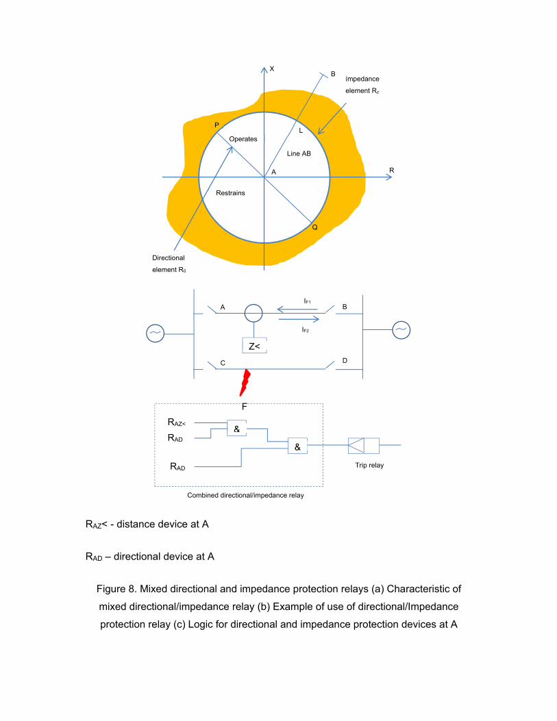
RAZ< - distance device at A
RAD – directional device at A
Figure 8. Mixed directional and impedance protection relays (a) Characteristic of
mixed directional/impedance relay (b) Example of use of directional/Impedance
protection relay (c) Logic for directional and impedance protection devices at A
Zone 1 R
X
Impedance
element Rz
B
Restrains
A
L
Line AB
Operates
P
Q
Directional
element R0
B
Z<
A
C D
F
IF1
IF2
RAD
RAD
RAZ< &
&
Trip relay
Combined directional/impedance relay
If a short circuit happens at F near to C on the parallel line CD, the directional unit RD
at A will hold due to current IF1. At the same time, the impedance element is retained
from performing by the inhibiting output of unit RD. If this control is not given, the under
impedance device could function prior to circuit breaker C tripping. Reversal of current
through the protection relay from IF1 to IF2 when C opens could then end in incorrect
operation of the healthy transmission line if the directional element RD performs before
the impedance unit resets. Thus, the need to address the adequate co-ordination of
multiple protection relay elements to achieve reliable protection relay performance
during evolving fault conditions, can be seen. In older protection relay arrangements,
the type of problem to be considered is typically mentioned as one of ‘contact race’.
SELF-POLARISED MHO PROTECTION RELAY
The mho impedance element is typically known as such since its characteristic is a
straight line on an admittance graph. It mixes the discriminating measures of both
reach control and directional control, therefore cancelling the ‘contact race’ issues that
may be found with separate reach and directional control devices. This is
accomplished by introduction of a polarizing signal. Mho impedance devices were
especially attractive for financial reasons where electromechanical relay devices were
used. Finally, they have been used worldwide for many years and their benefits and
drawbacks are now well known. For this reason they are still implemented in the
algorithms of some numerical protection relays. The characteristic of a mho
impedance device, when printed on an R/X graph, is a circle whose circumference
goes through the origin, as shown in Figure 9. This shows that the impedance device
is inherently directional and such that it will function only for short circuits in the forward
direction along line AB.
The impedance characteristic is adapted by setting Zn, the impedance reach, along
the diameter and φ, the angle of displacement of the diameter from the R axis. Angle
φ is known as the Relay Characteristic Angle (RCA). The relay performs for quantities
of fault impedance ZF within its characteristic. The self-polarised mho characteristic
can be found using a phase comparator circuit which compares input signals S2 and
S1 and performs whenever S2 lags S1 by between 90° and 270°, as presented in the
voltage graph of Figure 9.

The two input signals are:
where:
V - fault voltage from VT secondary
I - fault current from CT secondary
Zn - impedance setting of the zone
Zone 1 R
X
Restrain
φ
ZN
V
V=IZ0
Operate
Zone 1 R
X
Restrain
φ
ZN
ZF
B
Operate
A
Restrain
K
Q
R
X
φ
B
A
K
θ
P
AQ – Relay impedance setting
φ – Relay characteristic angle setting
AB – Protected transmission line
PQ – Arc resistance
θ – Line angle
Figure 9. Mho protection relay characteristics (a) Phase comparator inputs (b) Mho
impedance characteristics (c) Increased arc resistance coverage
The characteristic shown in Figure 9 (a) can be translated to the impedance plane of
Figure 9(b) by dividing each voltage by I. The impedance reach changes with short
circuit angle. As the protected transmission line is made up of resistance and
inductance, its short circuit current angle will depend upon the relative quantities of R
and X at the power system operating frequency. Under an arcing fault condition, or
ground fault involving extra resistance, such as tower footing resistance, the value of
the resistive element of short circuit impedance will raise to change the impedance
angle. Thus a protection relay having a characteristic angle same to the transmission
line angle will under reach under resistive short circuit conditions. Some engineers set
the RCA less than the transmission line angle, so that it is feasible to accept a small
quantity of short circuit resistance without causing under-reach. Nevertheless, when
setting the protection relay, the difference between the line angle θ and the protection
relay characteristic angle Ø has to be known. The resulting characteristic is presented
in Figure 9 where GL represents the length of the protected transmission line. With the
angle Ø set less than θ, the actual quantity of protected transmission line, AB, would
be same to the protection relay setting quantity AQ multiplied by cos(θ-Ø). Hence the
needed protection relay setting AQ is determined by:
cos
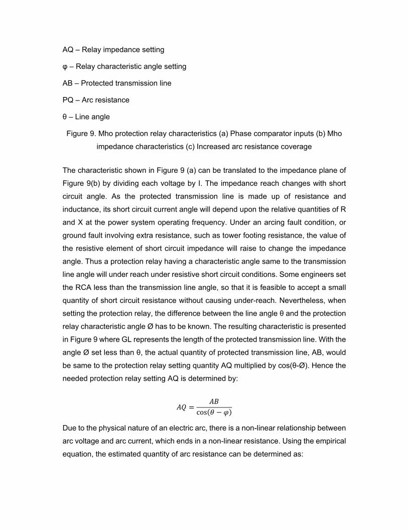
Due to the physical nature of an electric arc, there is a non-linear relationship between
arc voltage and arc current, which ends in a non-linear resistance. Using the empirical
equation, the estimated quantity of arc resistance can be determined as:
. (4) where:
Ra = arc resistance (ohms)
L = length of arc (metres)
I = arc current (A)
On long overhead transmission lines installed on steel towers with overhead ground
wires the impact of arc resistance can typically be neglected. The impact is
predominant on short overhead transmission lines and with short circuit currents below
2000A (i.e. minimum plant condition), or if the protected transmission line is of wood-
pole construction without ground wires. In the second case, the ground short circuit
resistance decreases the effective ground-fault reach of a ‘mho’ protection Zone 1
device to such an extent that the majority of short circuits are sensed in Zone 2 time.
This issue can typically be solved by using a protection relay with a cross-polarized
mho or a polygonal characteristic. Where an electrical power system is resistance-
grounded, it should be noted that this does not have to be treated with regard to the
protection relay settings other than the effect that decreased short circuit current may
have on the value of arc resistance sensed. The grounding resistance is in the source
behind the protection relay and only changes the source angle and source to
transmission line impedance ratio for ground faults. Hence, it would be considered
only when examining protection relay operation in terms of system impedance ratio.
OFFSET MHO/LENTICULAR CHARACTERISTICS
Under close up short circuit conditions, when the protection relay voltage drops to zero
or near-zero, a protection relay using a self-polarized mho characteristic or any other
shape of self-polarized directional impedance characteristic may not function when it
is needed to do so. Processes of covering this situation include the use of non-
directional impedance characteristics, such as offset mho, offset lenticular, or cross-
polarized and memory polarized directional impedance characteristics. If current bias
is used, the mho characteristic is shifted to embrace the origin, so that the measuring
device can function for close-up short circuits in both the forward and the reverse
directions. The offset mho protection relay has two main usages:

Figure 10. Common usage for the offset mho protection relay (a) Bus zone back-up
using an offset mho protection relay (b) Carrier starting in distance blocking
arrangements
THIRD PROTECTION ZONE AND BUSBAR BACK-UP PROTECTION ZONE
In this usage it is applied in conjunction with mho measuring devices as a short circuit
detector and/or protection Zone 3 measuring device. So, with the reverse reach set up
to extend into the bus protection zone, as presented in Figure 10, it will give back-up
protection for bus short circuits. This facility can be given with quadrilateral
characteristics. A further advantage of the protection Zone 3 usage is for Switch-on-
to-Fault (SOTF) protection, where the protection Zone 3 time delay would be by-
passed for a short period shortly following line switching to provide quick clearance of
a short circuit anywhere along the protected transmission line.
Zone 1 R
X
Busbar zone
Zone 2
Zone 3
Carrier start
H
J
Zone 1 R
X
Carrier stop Zone
2
Zone 3
G
K
CARRIER STARTING DEVICE IN DISTANCE PROTECTION ARRANGEMENTS
WITH CARRIER BLOCKING
If the offset mho device is utilized for starting carrier signalling, it is arranged as
presented in Figure 10. The carrier is transferred if the short circuit is external to the
protected transmission line but inside the reach of the offset mho protection relay, to
stop accelerated operation of the second or third zone protection relay at the remote
station. Transmission is reverted for internal short circuits by operation of the local
mho measuring devices, which provide high-speed fault clearance by the local and
remote end circuit breakers.
USAGE OF LENTICULAR CHARACTERISTIC
There is a possibility that the offset mho protection relay displayed in Figure 11 may
trip under maximum load transfer conditions if protection Zone 3 of the protection relay
has a big reach setting. A great protection Zone 3 reach may be needed to give remote
back-up protection for short circuits on the adjacent circuit. To avert this, a shaped
mode of characteristic may be utilized, where the resistive coverage is limited. With a
‘lenticular’ characteristic, the aspect ratio of the lens is changeable, allowing it to
be set to give the maximum short circuit resistance coverage consistent with
nonoperation under maximum load transfer situations. Figure 11 presents how the
lenticular characteristic can allow greater degrees of transmission line loading than
offset mho and plain impedance characteristics. Decrease of load impedance from ZD3
to ZD1 will relate to same rise in load current.

Figure 11. Minimum load impedance allowed with lenticular, offset mho and
impedance protection relays
It can be noted in Figure 11 how the load area is fixed according to a minimum
impedance arc, limited by straight lines which exhale from the origin, 0. Modem
numerical protection relays usually do not utilize lenticular characteristic shaping, but
alternatively utilize load encroachment (load blinder) sensing. This makes possible a
full mho characteristic to be utilized, but with tripping stopped in the region of the
impedance plane known to be frequented by load (ZA-ZB-ZC-ZD).
FULLY CROSS-POLARISED MHO CHARACTERISTIC
The previous paragraph presented how the non-directional offset mho characteristic
can inherently trip for close-up zero voltage short circuits, where there would be no
polarizing voltage to grant operation of a plain mho directional device. One way of
making sure the correct mho device response for zero-voltage short circuits is to add
a percentage of voltage from the healthy line(s) to the main polarizing voltage as a
substitute phase reference. This method is known as cross-polarizing, and it has the
benefit of keeping and increasing the directional features of the mho characteristic. By
the use of a phase voltage memory techniques, that gives several cycles of pre-short
circuit voltage reference during a short circuit, the cross-polarisation method is also
efficient for close-up three-phase short circuits. For this type of short circuit, no healthy
Impedance
characteristic
R
X
Offset Mho
characteristic b
Offset Lenticular
characteristic
a ZA
ZB ZC
Load
Area
ZD3 ZD2
ZD1
line voltage reference is usable.
Early memory system techniques were established on tuned, resonant circuits, but
issues happened when used in power networks where the power system operating
frequency could change. Sophisticated digital or numerical elements can provide a
synchronous line reference for changes in power system frequency before or during a
short circuit. Drawback of the self-polarized plain mho impedance characteristic, when
used on overhead transmission circuits with large impedance angles, is that it has
fixed coverage of arc or fault resistance. The issue is worsened in the situation of short
transmission circuits, since the needed protection Zone 1 ohmic setting is low. The
degree of the resistive coverage provided by the mho circle is linked to the forward
reach setting. Therefore, the ending resistive coverage may be too small in
comparison to the anticipated quantities of fault resistance. One extra advantage of
using cross-polarisation to a mho impedance device is that its resistive coverage will
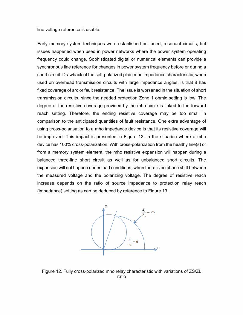
be improved. This impact is presented in Figure 12, in the situation where a mho
device has 100% cross-polarization. With cross-polarization from the healthy line(s) or
from a memory system element, the mho resistive expansion will happen during a
balanced three-line short circuit as well as for unbalanced short circuits. The
expansion will not happen under load conditions, when there is no phase shift between
the measured voltage and the polarizing voltage. The degree of resistive reach
increase depends on the ratio of source impedance to protection relay reach
(impedance) setting as can be deduced by reference to Figure 13.
Figure 12. Fully cross-polarized mho relay characteristic with variations of ZS/ZL ratio
X
R
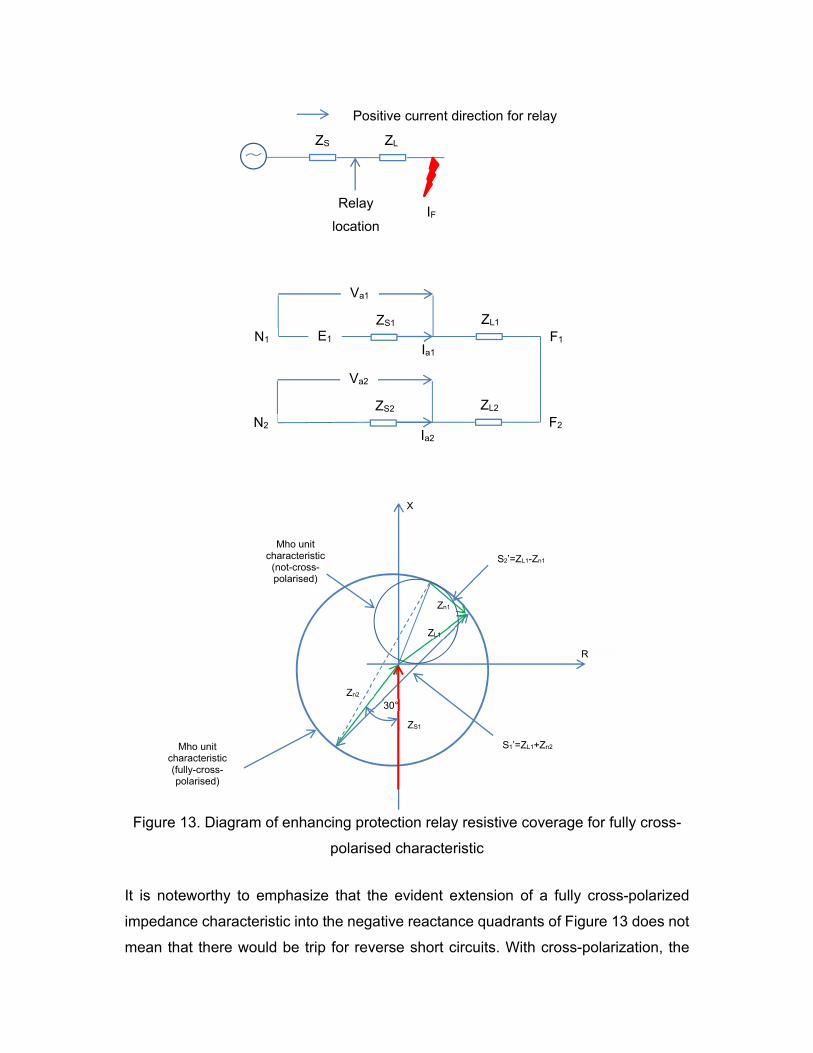
Figure 13. Diagram of enhancing protection relay resistive coverage for fully cross-
polarised characteristic
It is noteworthy to emphasize that the evident extension of a fully cross-polarized
impedance characteristic into the negative reactance quadrants of Figure 13 does not
mean that there would be trip for reverse short circuits. With cross-polarization, the
ZS
IF Relay
location
ZL
Positive current direction for relay
ZL1 ZS1 E1 N1
Ia1 F1
Va1
ZL2 ZS2 N2
Ia2 F2
Va2
S1’=ZL1+Zn2
R
X
S2’=ZL1-Zn1
Mho unit characteristic
(not-cross-polarised)
Mho unit characteristic (fully-cross-polarised)
ZS1
Zn2
ZL1
Zn1
30°

relay characteristic extends to cover the beginning of the impedance graph for forward
short circuits only. For reverse short circuits, the impact is to omit the beginning of the
impedance graph, thereby making sure adequate directional responses for close-up
forward or reverse short circuits. Fully cross-polarized characteristics have now greatly
been replaced, due to the trend of comparators linked to healthy line to trip under
heavy short circuit circumstances on another line. This is of no effect in a switched
distance protection relay, where a single comparator is linked to the adequate short
circuit loop impedance by starting units before measurement starts. Nevertheless,
modern protection relays provide independent impedance measurement for each of
the three ground-fault and three line-fault loops. For these protection relays, mal-
operation of live lines is unwanted, particularly when single-pole tripping is needed for
single-line short circuits.
PARTLY CROSS-POLARISED MHO CHARACTERISTIC
Where a dependable, independent technique of faulted line selection is not given, a
modern non switched distance protection relay may only use a comparatively small
percentage of cross polarisation. The picked out level has to be enough to give
dependable directional control in the presence of CVT transients for close-up short
circuits, and also achieve dependable faulted line selection. By using only partial
cross-polarisation, the drawback of the fully cross-polarised characteristic are averted,
while still keeping the benefits. Figure 14 presents a common characteristic that can
be found using this method.
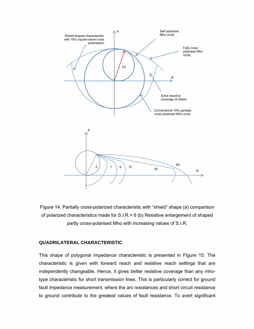
Figure 14. Partially cross-polarized characteristic with “shield” shape (a) comparison
of polarized characteristics made for S.I.R.= 6 (b) Resistive enlargement of shaped
partly cross-polarised Mho with increasing values of S.I.R.
QUADRILATERAL CHARACTERISTIC
This shape of polygonal impedance characteristic is presented in Figure 15. The
characteristic is given with forward reach and resistive reach settings that are
independently changeable. Hence, it gives better resistive coverage than any mho-
type characteristic for short transmission lines. This is particularly correct for ground
fault impedance measurement, where the arc resistances and short circuit resistance
to ground contribute to the greatest values of fault resistance. To avert significant
X
R
60 24
12 6 1 0
Extra resistive coverage of shield
R
X
Fully cross polarised Mho circle
Zn
Self polarised Mho circle
Conventional 16% partially cross polarized Mho circle
Shield-shaped characteristic with 16% square-wave cross
polarisation
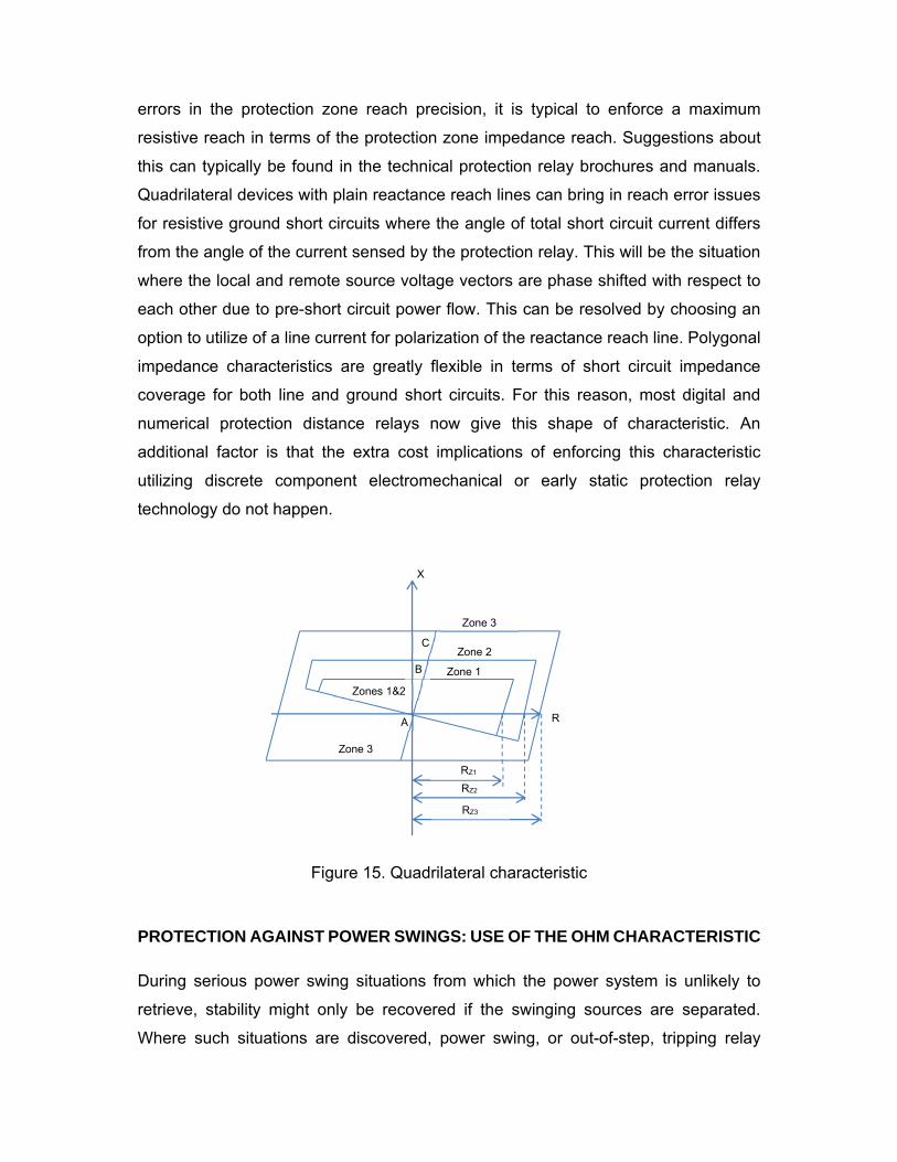
errors in the protection zone reach precision, it is typical to enforce a maximum
resistive reach in terms of the protection zone impedance reach. Suggestions about
this can typically be found in the technical protection relay brochures and manuals.
Quadrilateral devices with plain reactance reach lines can bring in reach error issues
for resistive ground short circuits where the angle of total short circuit current differs
from the angle of the current sensed by the protection relay. This will be the situation
where the local and remote source voltage vectors are phase shifted with respect to
each other due to pre-short circuit power flow. This can be resolved by choosing an
option to utilize of a line current for polarization of the reactance reach line. Polygonal
impedance characteristics are greatly flexible in terms of short circuit impedance
coverage for both line and ground short circuits. For this reason, most digital and
numerical protection distance relays now give this shape of characteristic. An
additional factor is that the extra cost implications of enforcing this characteristic
utilizing discrete component electromechanical or early static protection relay
technology do not happen.
Figure 15. Quadrilateral characteristic
PROTECTION AGAINST POWER SWINGS: USE OF THE OHM CHARACTERISTIC
During serious power swing situations from which the power system is unlikely to
retrieve, stability might only be recovered if the swinging sources are separated.
Where such situations are discovered, power swing, or out-of-step, tripping relay
Zone 2
Zone 1
R
X
Zone 3
A
Zone 3
C
B
Zones 1&2
RZ1
RZ2
RZ3
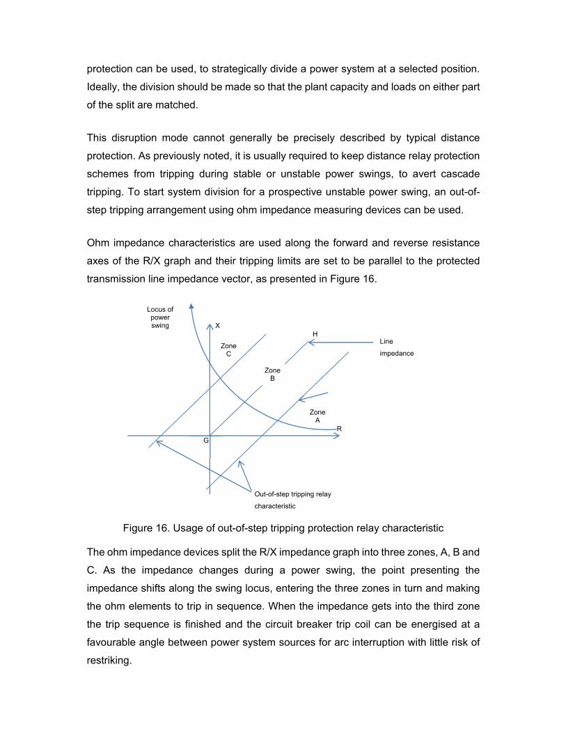
protection can be used, to strategically divide a power system at a selected position.
Ideally, the division should be made so that the plant capacity and loads on either part
of the split are matched.
This disruption mode cannot generally be precisely described by typical distance
protection. As previously noted, it is usually required to keep distance relay protection
schemes from tripping during stable or unstable power swings, to avert cascade
tripping. To start system division for a prospective unstable power swing, an out-of-
step tripping arrangement using ohm impedance measuring devices can be used.
Ohm impedance characteristics are used along the forward and reverse resistance
axes of the R/X graph and their tripping limits are set to be parallel to the protected
transmission line impedance vector, as presented in Figure 16.
Figure 16. Usage of out-of-step tripping protection relay characteristic
The ohm impedance devices split the R/X impedance graph into three zones, A, B and
C. As the impedance changes during a power swing, the point presenting the
impedance shifts along the swing locus, entering the three zones in turn and making
the ohm elements to trip in sequence. When the impedance gets into the third zone
the trip sequence is finished and the circuit breaker trip coil can be energised at a
favourable angle between power system sources for arc interruption with little risk of
restriking.
H
Out-of-step tripping relay
characteristic
Zone A
R
X
Line
impedance
Zone B
Zone C
G
Locus of power swing

Only an unstable power swing situation can make the impedance vector to shift
through the three zones. Hence, other types of system disruptions, such as power
system short circuit conditions, will not end in protection relay element trip.
OTHER CHARACTERISTICS
The performance time for the algorithm for typical distance relay protection using
quadrilateral or similar characteristics may end in a long tripping time, perhaps up to
40 ms in some protection relay arrangements. To get over this, some numerical
distance protection relays also use extra algorithms that can be carried out significantly
quicker. These algorithms are based typically on sensing variations in current and
voltage that are in surplus of what is anticipated.
This algorithm senses a short circuit by cross-comparing the measured quantities of
current and voltage with the previously sampled quantities. If the variation between
these samples surpasses a predefined quantity, it is presumed a short circuit has
happened. In parallel, the distance to fault location is also calculated. Given the
calculated distance to fault lies within the protection Zone reach of the protection relay,
a trip command is issued. This algorithm can be carried out quicker than the typical
distance algorithm, ending in quicker overall functioning times. Faulted line selection
can be carried out by cross-comparing the signs of the variations in voltage and
current. Protection relays that use these algorithms typically run both this and typical
distance protection algorithms in parallel, as some short circuit types (e.g. high-
resistance short circuits) may not fall within the short circuit detection criteria of the
algorithm.
DISTANCE PROTECTION RELAY USAGE
Discriminating protection zones can be accomplished using distance protection relays
given that fault distance is a simple function of impedance. While this is true for
transmission lines, the impedances sensed by a distance protection relay also depend
on the following points:
- the magnitudes of current and voltage (the protection relay may not see all the
current that generates the short circuit voltage)
- the fault impedance loop being sensed
- the type of short circuit
- the short circuit resistance
- the symmetry of transmission line impedance
- the circuit arrangement (single, double or multi-terminal transmission line)
It is feasible to eliminate all of the above points for all practical operating situations.
Nevertheless, significant success can be made with an adequate distance protection
relay. This may incorporate protection relay devices or algorithms for starting, distance
sensing and for scheme logic. Different distance protection relay formats exist and
they depend on the tripping speed needed and cost conditions related to the protection
relaying hardware, software or numerical protection relay processing capacity needed.
The most typical formats are:
- a single sensing device for each line is given, that covers all line short circuits
- a more economical scheme is for ‘starter’ devices to check which line or lines
have experienced a short circuit. The starter devices switch a single sensing
device or algorithm to sense the most appropriate short circuit impedance loop.
This is typically referred to as a switched distance protection relay
- a single set of impedance sensing devices for each impedance loop may have
their reach settings growingly raised from one zone reach setting to another.
The gain happens after zone time delays that are started by functioning of
starter devices. This type of protection relay is typically referred to as a reach
stepped distance protection relay.
- each protection zone may be given with independent sets of impedance
sensing devices for each impedance loop. This is known as a full distance

protection arrangement, capable of providing the greatest performance in terms
of speed and application flexibility
Moreover, relay protection against ground faults may need different characteristics
and/or settings to those needed for line short circuits, ending in extra elements being
needed. A total of 18 impedance-sensing devices or algorithms would be needed in a
complete arrangement distance protection relay for three zone protection for all types
of short circuits. With electromechanical or static arrangement, each of the sensing
devices would have been a separate protection relay placed in its own enclosing, so
that the distance protection relay comprised a panel-mounted assembly of the needed
protection relays with suited inter-unit wiring.
Digital/numerical distance protection relays are likely to have all of the above functions
incorporated in software. Starter elements may not be needed. The complete distance
protection relay is placed in a single enclosure, making for great savings in space,
wiring and enhanced dependability, through the enhanced availability that stems from
the provision of uninterrupted self-supervision.
STARTERS FOR SWITCHED DISTANCE RELAY PROTECTION
Electromechanical and static distance protection relays do not typically use separate
impedance-sensing device per phase. The cost and the final physical arrangement
size made this arrangement impractical, except for the most comprehensive EHV
transmission usages. To accomplish economy for other usages, only one sensing
device was given, together with ‘starter’ elements that detected which lines were short
circuited, to switch the adequate signals to the single measuring function. A distance
protection relay using this method is known as a switched distance protection relay. A
number of different modes of starters have been utilized, the most typical being based
on over-current, under-voltage or under-impedance sensing.
Numerical distance protection relays allow direct sensing of the lines involved in a
short circuit. This is known as short circuit line selection, often abbreviated to line
selection. Several methods are available for short circuit line selection, which then
allows the adequate distance-sensing zone to operate. Without line selection, the relay
protection risks having over or under-reach issues, or tripping three-line when single-

pole short circuit clearance is needed. Several modes are available for short circuit
phase selection, such as:
- Superimposed current comparisons, cross-comparing the step change of level
between pre-short circuit load, and short circuit current. This allows very quick
sensing of the faulted lines, within only several samples of the analogue current
inputs
- change in voltage magnitude
- change in current magnitude
Numerical line selection is quicker than traditional starter methods utilized in
electromechanical or static distance protection relays. It does not enforce a time
penalty as the line selection and sensing zone algorithms operate in parallel. It is
feasible to make a full-arrangement protection relay with these numerical methods.
The line selection algorithm gives short circuited line selection, together with a
segregated sensing algorithm for each line-earth and line to line short circuit loop (AN,
BN, CN, AB, BC, CA), thus assuring complete-scheme operation.
Nevertheless, there may be situations where a numerical protection relay that mimics
earlier switched distance protection methods is needed. The reasons may be
economic (less software needed) - therefore cheaper than a protection relay that
contains a complete-arrangement implementation) and/or technical. Some usages
may need the numerical protection relay characteristics to match those of earlier
generations already established in a transmission network, to help and enhance
selectivity. Such protection relays are usable, often with refinements such as multi-
sided polygonal impedance characteristics that help in averting tripping due to heavy
load situations. With electromechanical or static switched distance protection relays,
a selection of available starters usually had to be made. The selection of starter was
dependent on power system parameters such as maximum load transfer in relation to
maximum reach needed and power system grounding schemes.
Where overcurrent starters are utilized, care has to be taken to assure that, with
minimum generating plant in operation, the setting of the overcurrent starters is
sufficiently sensitive to sense short circuits beyond the third zone. Moreover, these
starters need a high drop-off to pick-up ratio, to assure that they will drop off under
maximum load conditions after a second or third zone short circuit has been cleared
by the first zone protection relay in the faulty section. Without this characteristic,
indiscriminate operation may end for subsequent short circuits in the second or third
protection zone. For acceptable tripping of the overcurrent starters in a switched
distance protection scheme, the next conditions have to be met:
- the current setting of the overcurrent starters must be not less than 1.2 times
the maximum full load current of the protected transmission line
- the power system minimum short circuit current for a short circuit at the Zone 3
reach of the distance protection relay must not be less than 1.5 times the setting
of the overcurrent starters
On multiple-grounded power systems where the neutrals of all the power transformers
are directly grounded, or in power systems where the short circuit current is less than
the full load current of the protected transmission line, it is not feasible to use
overcurrent starters. In these situations under-impedance starters are commonly
used. The type of under-impedance starter utilized is typically dependent on the
maximum anticipated load current and same minimum load impedance in relation to
the needed protection relay setting to cover short circuits in Zone 3. This is shown in
Figure 11 where ZD1, ZD2, and ZD3 are respectively the minimum load impedances
allowed when lenticular, offset mho and impedance protection relays are utilized.


![New record of the dinoflagellate Unruhdinium penardii var. robustum146-151]KJM20-034.pdf · 2020-06-30 · The Han River is an important water resource in Seoul and the metropolitan](https://static.fdocument.org/doc/165x107/5f3f3367b452d5602b742d63/new-record-of-the-dinoflagellate-unruhdinium-penardii-var-146-151kjm20-034pdf.jpg)


![ALplus2-ALCplus2 (ACM PDH Radio Link) - Training Manual [Modo de Compatibilidad]](https://static.fdocument.org/doc/165x107/55cf98e0550346d0339a2f7c/alplus2-alcplus2-acm-pdh-radio-link-training-manual-modo-de-compatibilidad.jpg)