Long-range programme in neutrino physics: superbeam, β beam, neutrino factory
SELOCKEY.SOA TM1990A-F5
TM1990A-F5 10-1
TM1990A SPECIAL FEATURES
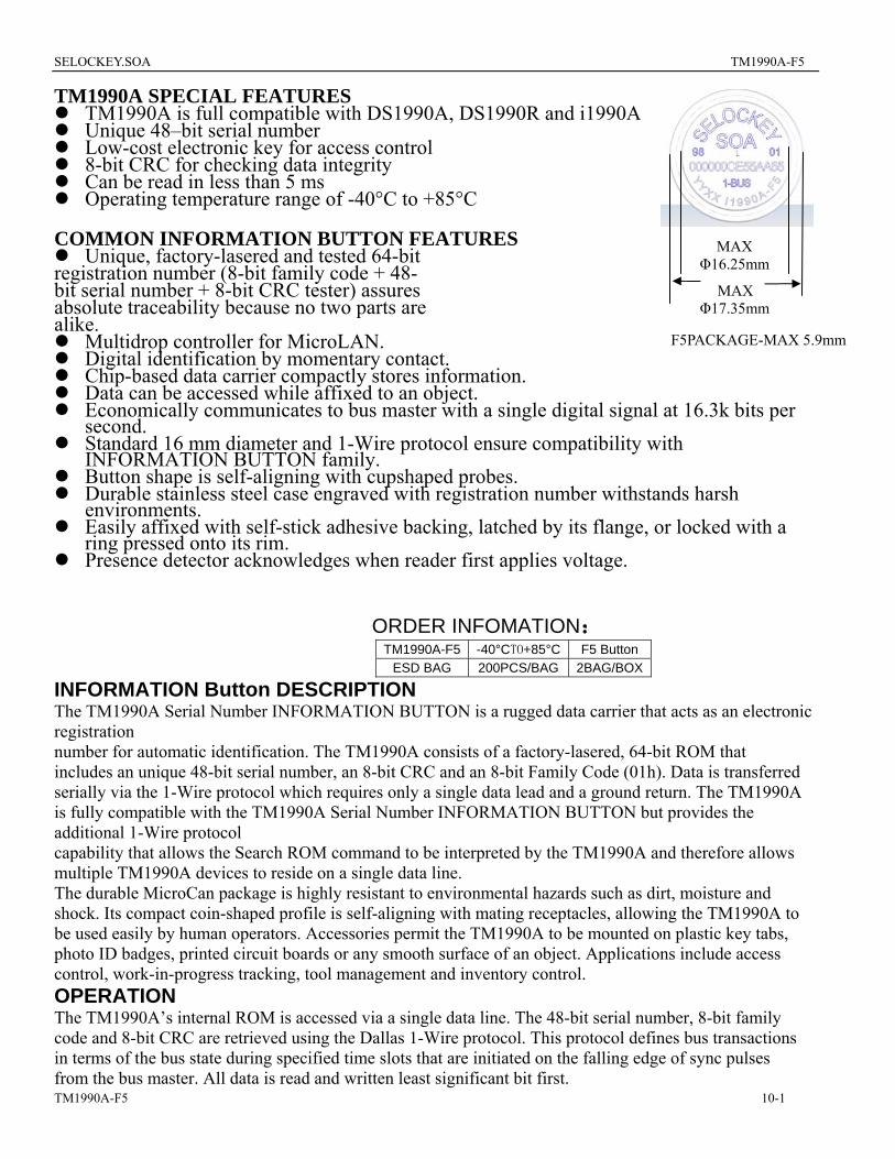
MAX Φ16.25mm
MAX Φ17.35mm
TM1990A is full compatible with DS1990A, DS1990R and i1990A Unique 48–bit serial number Low-cost electronic key for access control 8-bit CRC for checking data integrity Can be read in less than 5 ms Operating temperature range of -40°C to +85°C
COMMON INFORMATION BUTTON FEATURES
Unique, factory-lasered and tested 64-bit registration number (8-bit family code + 48- bit serial number + 8-bit CRC tester) assures absolute traceability because no two parts are alike.
Multidrop controller for MicroLAN. F5PACKAGE-MAX 5.9mm Digital identification by momentary contact. Chip-based data carrier compactly stores information. Data can be accessed while affixed to an object. Economically communicates to bus master with a single digital signal at 16.3k bits per
second. Standard 16 mm diameter and 1-Wire protocol ensure compatibility with
INFORMATION BUTTON family. Button shape is self-aligning with cupshaped probes. Durable stainless steel case engraved with registration number withstands harsh
environments. Easily affixed with self-stick adhesive backing, latched by its flange, or locked with a
ring pressed onto its rim. Presence detector acknowledges when reader first applies voltage.
ORDER INFOMATION: TM1990A-F5 -40°CTO+85°C F5 Button
ESD BAG 200PCS/BAG 2BAG/BOX
INFORMATION Button DESCRIPTION The TM1990A Serial Number INFORMATION BUTTON is a rugged data carrier that acts as an electronic registration number for automatic identification. The TM1990A consists of a factory-lasered, 64-bit ROM that includes an unique 48-bit serial number, an 8-bit CRC and an 8-bit Family Code (01h). Data is transferred serially via the 1-Wire protocol which requires only a single data lead and a ground return. The TM1990A is fully compatible with the TM1990A Serial Number INFORMATION BUTTON but provides the additional 1-Wire protocol capability that allows the Search ROM command to be interpreted by the TM1990A and therefore allows multiple TM1990A devices to reside on a single data line. The durable MicroCan package is highly resistant to environmental hazards such as dirt, moisture and shock. Its compact coin-shaped profile is self-aligning with mating receptacles, allowing the TM1990A to be used easily by human operators. Accessories permit the TM1990A to be mounted on plastic key tabs, photo ID badges, printed circuit boards or any smooth surface of an object. Applications include access control, work-in-progress tracking, tool management and inventory control. OPERATION The TM1990A’s internal ROM is accessed via a single data line. The 48-bit serial number, 8-bit family code and 8-bit CRC are retrieved using the Dallas 1-Wire protocol. This protocol defines bus transactions in terms of the bus state during specified time slots that are initiated on the falling edge of sync pulses from the bus master. All data is read and written least significant bit first.
SELOCKEY.SOA TM1990A-F5
TM1990A-F5 10-2
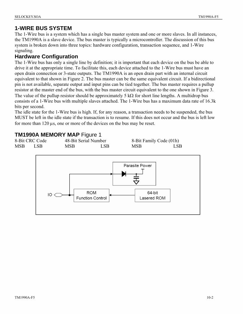
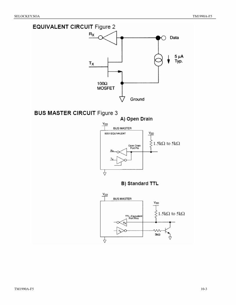
1-WIRE BUS SYSTEM The 1-Wire bus is a system which has a single bus master system and one or more slaves. In all instances, the TM1990A is a slave device. The bus master is typically a microcontroller. The discussion of this bus system is broken down into three topics: hardware configuration, transaction sequence, and 1-Wire signaling. Hardware Configuration The 1-Wire bus has only a single line by definition; it is important that each device on the bus be able to drive it at the appropriate time. To facilitate this, each device attached to the 1-Wire bus must have an open drain connection or 3-state outputs. The TM1990A is an open drain part with an internal circuit equivalent to that shown in Figure 2. The bus master can be the same equivalent circuit. If a bidirectional pin is not available, separate output and input pins can be tied together. The bus master requires a pullup resistor at the master end of the bus, with the bus master circuit equivalent to the one shown in Figure 3. The value of the pullup resistor should be approximately 5 kΩ for short line lengths. A multidrop bus consists of a 1-Wire bus with multiple slaves attached. The 1-Wire bus has a maximum data rate of 16.3k bits per second. The idle state for the 1-Wire bus is high. If, for any reason, a transaction needs to be suspended, the bus MUST be left in the idle state if the transaction is to resume. If this does not occur and the bus is left low for more than 120 µs, one or more of the devices on the bus may be reset. TM1990A MEMORY MAP Figure 1 8-Bit CRC Code 48-Bit Serial Number 8-Bit Family Code (01h) MSB LSB MSB LSB MSB LSB
SELOCKEY.SOA TM1990A-F5
TM1990A-F5 10-3
SELOCKEY.SOA TM1990A-F5
TM1990A-F5 10-4
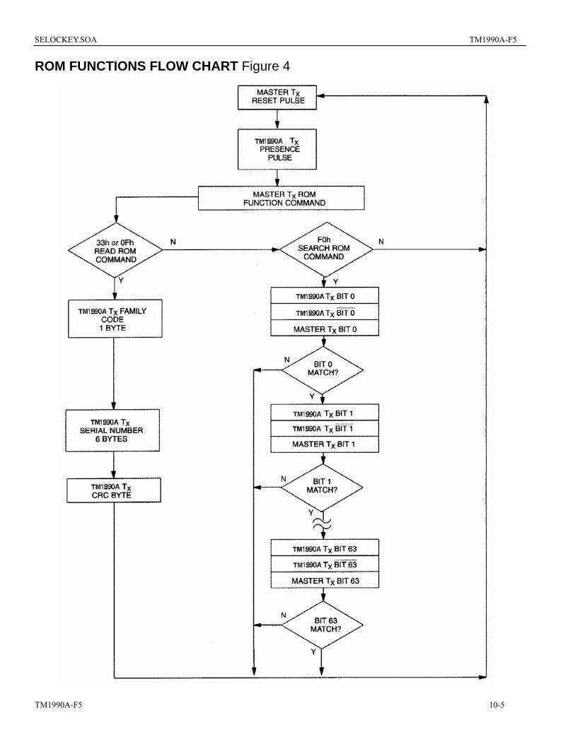
INITIALIZATION All transactions on the 1-Wire bus begin with an initialization sequence. The initialization sequence consists of a reset pulse transmitted by the bus master followed by a presence pulse(s) transmitted by the slave(s). The presence pulse lets the bus master know that the TM1990A is on the bus and is ready to operate. ROM FUNCTION COMMANDS Once the bus master has detected a presence, it can issue one of the four ROM function commands. All ROM function commands are eight bits long. A list of these commands follows (refer to flowchart in Figure 4): Read ROM [33h] or [0Fh] This command allows the bus master to read the TM1990A’s 8-bit family code, unique 48-bit serial number, and 8-bit CRC. This command can only be used if there is a single TM1990A on the bus. If more than one slave is present on the bus, a data collision will occur when all slaves try to transmit at the same time (open drain will produce a wired-AND result). The TM1990A Read ROM function will occur with a command byte of either 33h or 0Fh in order to ensure compatibility with the TM1990, which will only respond to a 0Fh command word with its 64-bit ROM data. Match ROM [55h] / Skip ROM [CCh] The complete 1-Wire protocol for all Dallas Semiconductor INFORMATION BUTTONs contains a Match ROM and a Skip ROM command. Since the TM1990A contains only the 64bit ROM with no additional data fields, the Match ROM and Skip ROM are not applicable and will cause no further activity on the 1-Wire bus if executed. The TM1990A does not interfere with other 1-Wire parts on a multidrop bus that do respond to a Match ROM or Skip ROM . Search ROM [F0h] When a system is initially brought up, the bus master might not know the number of devices on the 1- Wire bus or their 64-bit ROM codes. The search ROM command allows the bus master to use a process of elimination to identify the 64-bit ROM codes of all slave devices on the bus. The ROM search process is the repetition of a simple 3-step routine: read a bit, read the complement of the bit, then write the desired value of that bit. The bus master performs this simple 3-step routine on each bit of the ROM. After one complete pass, the bus master knows the contents of the ROM in one device. The remaining number of devices and their ROM codes may be identified by additional passes.
SELOCKEY.SOA TM1990A-F5
TM1990A-F5 10-5
ROM FUNCTIONS FLOW CHART Figure 4
SELOCKEY.SOA TM1990A-F5
TM1990A-F5
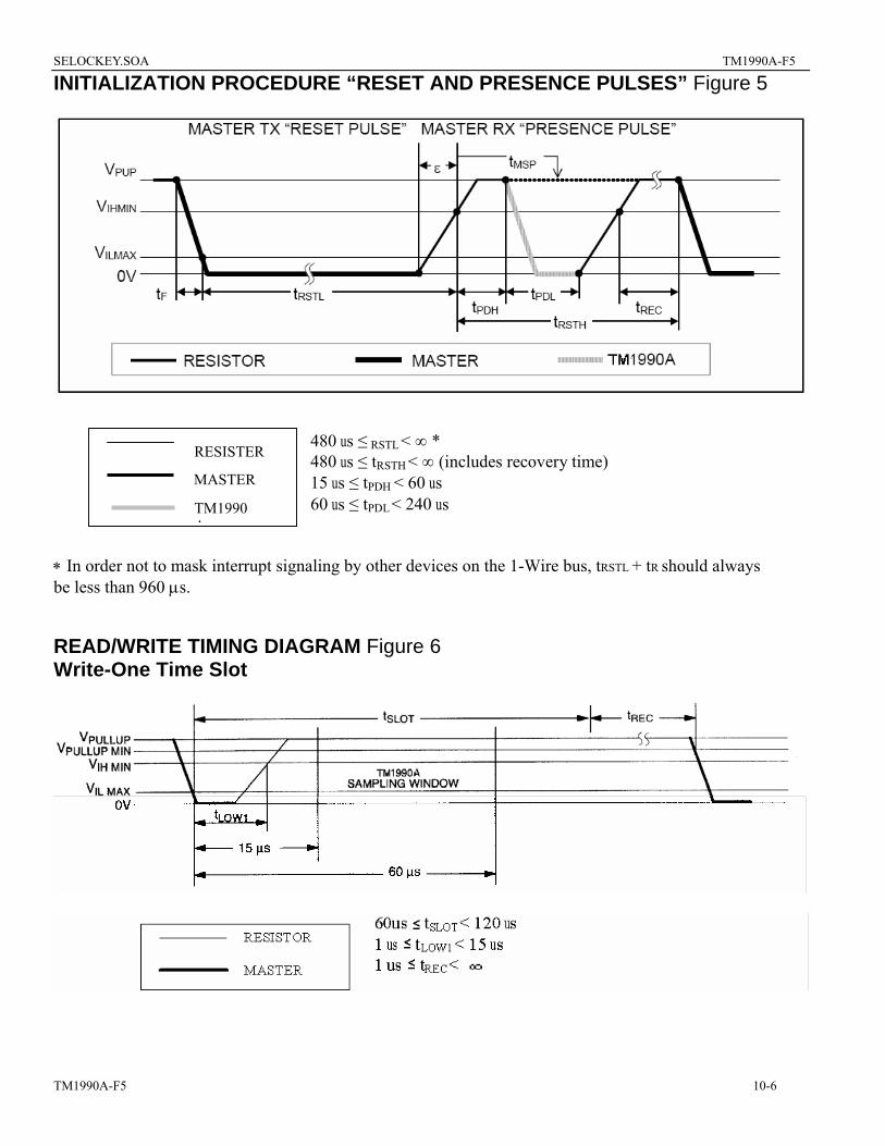
INITIALIZATION PROCEDURE “RESET AND PRESENCE PULSES” Figure 5
480 us ≤ RSTL < ∞ * RESISTER 480 us ≤ tRSTH < ∞ (includes recovery time) MASTER 15 us ≤ tPDH < 60 us
60 us ≤ tPDL < 240 us
∗ In order not to mbe less than 960 µs
READ/WRITE Write-One Tim
TM1990
10-6
A
ask interrupt signaling by other devices on the 1-Wire bus, tRSTL + tR should always .
TIMING DIAGRAM Figure 6 e Slot
SELOCKEY.SOA TM1990A-F5
TM1990A-F5
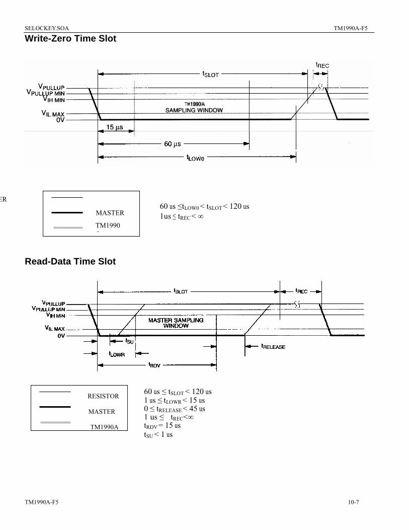
Write-Zero Time Slot
ER 60 us ≤tLOW0 < tSLOT < 120 us
MASTER 1us ≤ tREC < ∞
A
Read-Data Time Slot
RESISTOR
MASTER
TM1990A
60 us ≤ tSLOT < 120 us1 us ≤ tLOWR < 15 us 0 ≤ tRELEASE < 45 us 1 us ≤ tREC<∞ tRDV = 15 us tSU < 1 us
TM1990
10-7
SELOCKEY.SOA TM1990A-F5
TM1990A-F5 10-8
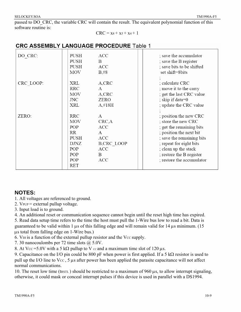
CRC GENERATION To validate the data transmitted from the TM1990A, the bus master may generate a CRC value from the data as it is received. This generated value is compared to the value stored in the last eight bits of the TM1990A. The bus master computes the CRC over the 8-bit family code and all 48 ID number data bits, but not over the stored CRC value itself. If the two CRC values match, the transmission is error-free. An example of how to generate the CRC using assembly language software is shown in Table 1. This assembly language code is written for the 8031/51 Microcontroller family. The procedure DO_CRC calculates the cumulative CRC of all the bytes passed to it in the accumulator. It should be noted that the variable CRC needs to be initialized to 0 before the procedure is executed. Each byte of the data is then placed in the accumulator and DO-CRC is called to update the CRC variable. After all the data has been
SELOCKEY.SOA TM1990A-F5
passed to DO_CRC, the variable CRC will contain the result. The equivalent polynomial function of this software routine is:
CRC = x8 + x5 + x4 + 1
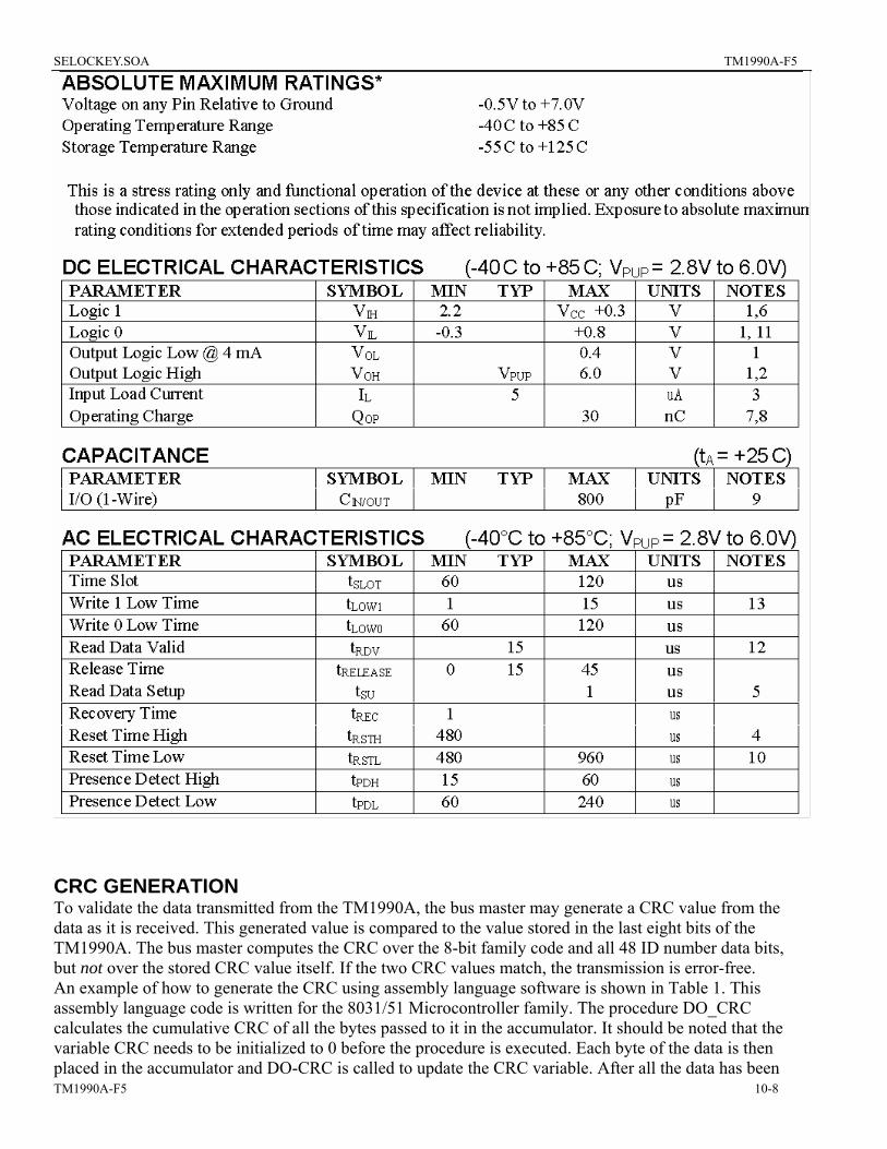
NOTES: 1. All voltages are referenced to ground. 2. VPUP = external pullup voltage. 3. Input load is to ground. 4. An additional reset or communication sequence cannot begin until the reset high time has expired. 5. Read data setup time refers to the time the host must pull the 1-Wire bus low to read a bit. Data is guaranteed to be valid within 1 µs of this falling edge and will remain valid for 14 µs minimum. (15 µs total from falling edge on 1-Wire bus.) 6. VIH is a function of the external pullup resistor and the VCC supply. 7. 30 nanocoulombs per 72 time slots @ 5.0V. 8. At VCC =5.0V with a 5 kΩ pullup to V CC and a maximum time slot of 120 µs. 9. Capacitance on the I/O pin could be 800 pF when power is first applied. If a 5 kΩ resistor is used to pull up the I/O line to VCC , 5 µs after power has been applied the parasite capacitance will not affect normal communications. 10. The reset low time (tRSTL ) should be restricted to a maximum of 960 µs, to allow interrupt signaling, otherwise, it could mask or conceal interrupt pulses if this device is used in parallel with a DS1994.
TM1990A-F5 10-9

SELOCKEY.SOA
TM1990A-f5 10 of 10