Coherent-StingRay-Data-Sheet.pdf - … · Coherent StingRay. In today’s world of expanding 3. D...
8
Triangulation Base y x Matrix Camera Camera Pixel Illumination FOV Shaped Object Laser Line Object Pixel z d l α β d = l sin α sin β / sin (α + β) Superior Reliability & Performance Coherent StingRay In today’s world of expanding 3D vision systems, the camera and laser are equal partners in the accuracy, stability and repeatability of the measurements made and used by these applications. The requirements on the laser for uniformity, power, pointing and electrical stability are far above a typical illumination system requirements. Having a source which produces very high power density, very thin measurement cross sections with a uniform return that does not mask the profile of the object is critical to the continued success of these demanding applications. The technology and advancement of these lasers has stayed the same for many years now, not giving the user the ability to leverage this portion of the system beyond its current technology. The Coherent StingRay laser platform is a re-vision of this technology, taking technology and best practices from leading edge applications in Bioinstrumen- tation and Laser Measurement and Control. The Coherent StingRay laser incor- porates state of the art electronics, optics and mechanics to provide a compact, highly flexible and reliable laser source that re-sets the standard in Machine Vision. 3D Triangulation Theory Structured Light Pattern Generating Laser Coherent StingRay Features: • 450 nm to 830 nm • Power up to 200 mW • Uniformity up to 95% • External focusability • Pointing <10 μrad/°C • Microprocessor controlled • Advanced service monitor • RS-232 controllable with GUI interface • Auto scaling input power 5 to 24 VDC Coherent StingRay Applications: • Non-contact Height Measurements • Automotive Production • Extrusion Measurements • Medical/Dental • Transportation • Wood Processing • Steel Production • Microelectronics Inspection • Food Portioning/Inspection • Glass Inspection www.Coherent.com/CoherentStingRay
Transcript of Coherent-StingRay-Data-Sheet.pdf - … · Coherent StingRay. In today’s world of expanding 3. D...
Triangulation Base
yx
Matrix Camera
Camera Pixel
IlluminationFOV
ShapedObject
LaserLine Object
Pixel
z
d
l
α β
d = l sin α sin β / sin (α + β)
Superior Reliability & Performance
Coherent StingRay
In today’s world of expanding 3D vision systems, the camera and laser are equal partners in the accuracy, stability and repeatability of the measurements made and used by these applications. The requirements on the laser for uniformity, power, pointing and electrical stability are far above a typical illumination system requirements. Having a source which produces very high power density, very thin measurement cross sections with a uniform return that does not mask the profile of the object is critical to the continued success of these demanding applications. The technology and advancement of these lasers has stayed the same for many years now, not giving the user the ability to leverage this portion of the system beyond its current technology.
The Coherent StingRay laser platform is a re-vision of this technology, taking technology and best practices from leading edge applications in Bioinstrumen-tation and Laser Measurement and Control. The Coherent StingRay laser incor-porates state of the art electronics, optics and mechanics to provide a compact, highly flexible and reliable laser source that re-sets the standard in Machine Vision.
3D Triangulation Theory
Structured Light Pattern Generating Laser
Coherent StingRay Features:
• 450 nm to 830 nm
• Power up to 200 mW
• Uniformity up to 95%
• External focusability
• Pointing <10 μrad/°C
• Microprocessor controlled
• Advanced service monitor
• RS-232 controllable with GUI interface
• Auto scaling input power 5 to 24 VDC
Coherent StingRay Applications:
• Non-contact Height Measurements
• Automotive Production
• Extrusion Measurements
• Medical/Dental
• Transportation
• Wood Processing
• Steel Production
• Microelectronics Inspection
• Food Portioning/Inspection
• Glass Inspection
www.Coherent.com/CoherentStingRay
System Specifications Coherent Coherent Coherent Coherent Coherent StingRay-450 StingRay-520 StingRay-639 StingRay-640 StingRay-655
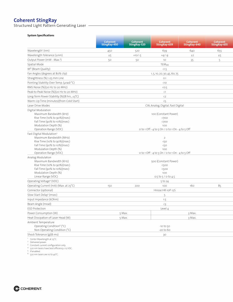
Wavelength1 (nm) 450 520 639 640 655Wavelength Tolerance (±nm) ±5 +10/-5 +4/-9 ±2 ±5Output Power (mW - Max.2) 50 50 10 35 5Spatial Mode TEM00M2 (Beam Quality) <1.5Fan Angles (degrees at 80% clip) 1, 5, 10, 20, 30, 45, 60, 75Straightness (%) >25 mm Line 0.1Pointing Stability Over Temp. (µrad/°C) <10RMS Noise (%)(20 Hz to 20 MHz) <0.5Peak- to- Peak Noise (%)(20 Hz to 20 MHz) <1Long- Term Power Stability (%)(8 hrs., ±3°C) <2Warm -Up Time (minutes)(from Cold Start) <5Laser Drive Modes CW, Analog, Digital, Fast DigitalDigital Modulation Maximum Bandwidth (kHz) 100 (Constant Power) Rise Time (10% to 90%)(nsec) <700 Fall Time (90% to 10%)(nsec) <700 Modulation Depth (%) 100 Operation Range (VDC) 0 to 1 Off - 4 to 5 On / 0 to 1 On - 4 to 5 OffFast Digital Modulation3
Maximum Bandwidth (MHz) 2 Rise Time (10% to 90%)(nsec) <50 Fall Time (90% to 10%)(nsec) <50 Modulation Depth (%) 100 Operation Range (VDC) 0 to 1 Off - 4 to 5 On / 0 to 1 On - 4 to 5 OffAnalog Modulation Maximum Bandwidth (KHz) 500 (Constant Power) Rise Time (10% to 90%)(nsec) <500 Fall Time (90% to 10%)(nsec) <500 Modulation Depth (%) 100 Linear Range (VDC) 0.5 to 5 / 0 to 4.5Operating Voltage4 (VDC) 5 to 24Operating Current (mA)-(Max. at 25°C) 150 200 100 160 85Connector (optional) Hirose HR-10P-12SSlow Start Delay5 (msec) 5Input Impedance (kOhm) 1.5Beam Angle (mrad) <3ESD Protection Level 4Power Consumption (W) 5 Max. 3 Max.Heat Dissipation of Laser Head (W) 5 Max. 3 Max.Ambient Temperature Operating Condition6 (°C) -10 to 50 Non -Operating Condition (°C) -20 to 60Shock Tolerance (g)(6 ms) 301 Center Wavelength at 25°C.2 Delivered power.3 Constant current configuration only.4 520 nm lasers have best efficiency >12 VDC.5 If enabled.6 520 nm lasers are 10 to 40°C.
Structured Light Pattern Generating LaserCoherent StingRay
System Specifications Coherent Coherent Coherent Coherent Coherent Coherent StingRay-660 StingRay-660 StingRay-660 StingRay-685 StingRay-785 StingRay-830
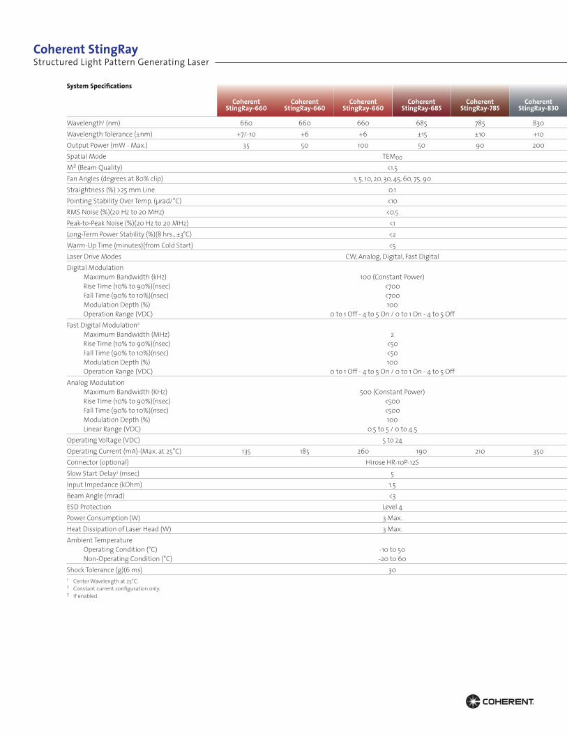
Wavelength1 (nm) 660 660 660 685 785 830Wavelength Tolerance (±nm) +7/-10 +6 +6 ±15 ±10 +10Output Power (mW - Max.) 35 50 100 50 90 200Spatial Mode TEM00M2 (Beam Quality) <1.5Fan Angles (degrees at 80% clip) 1, 5, 10, 20, 30, 45, 60, 75, 90Straightness (%) >25 mm Line 0.1Pointing Stability Over Temp. (µrad/°C) <10RMS Noise (%)(20 Hz to 20 MHz) <0.5Peak- to- Peak Noise (%)(20 Hz to 20 MHz) <1Long- Term Power Stability (%)(8 hrs., ±3°C) <2Warm -Up Time (minutes)(from Cold Start) <5Laser Drive Modes CW, Analog, Digital, Fast DigitalDigital Modulation Maximum Bandwidth (kHz) 100 (Constant Power) Rise Time (10% to 90%)(nsec) <700 Fall Time (90% to 10%)(nsec) <700 Modulation Depth (%) 100 Operation Range (VDC) 0 to 1 Off - 4 to 5 On / 0 to 1 On - 4 to 5 OffFast Digital Modulation2
Maximum Bandwidth (MHz) 2 Rise Time (10% to 90%)(nsec) <50 Fall Time (90% to 10%)(nsec) <50 Modulation Depth (%) 100 Operation Range (VDC) 0 to 1 Off - 4 to 5 On / 0 to 1 On - 4 to 5 OffAnalog Modulation Maximum Bandwidth (KHz) 500 (Constant Power) Rise Time (10% to 90%)(nsec) <500 Fall Time (90% to 10%)(nsec) <500 Modulation Depth (%) 100 Linear Range (VDC) 0.5 to 5 / 0 to 4.5Operating Voltage (VDC) 5 to 24Operating Current (mA)-(Max. at 25°C) 135 185 260 190 210 350Connector (optional) Hirose HR-10P-12SSlow Start Delay3 (msec) 5Input Impedance (kOhm) 1.5Beam Angle (mrad) <3ESD Protection Level 4Power Consumption (W) 3 Max.Heat Dissipation of Laser Head (W) 3 Max.Ambient Temperature Operating Condition (°C) -10 to 50 Non -Operating Condition (°C) -20 to 60Shock Tolerance (g)(6 ms) 301 Center Wavelength at 25°C.2 Constant current configuration only.3 If enabled.
Structured Light Pattern Generating LaserCoherent StingRay
Mechanical Specifications
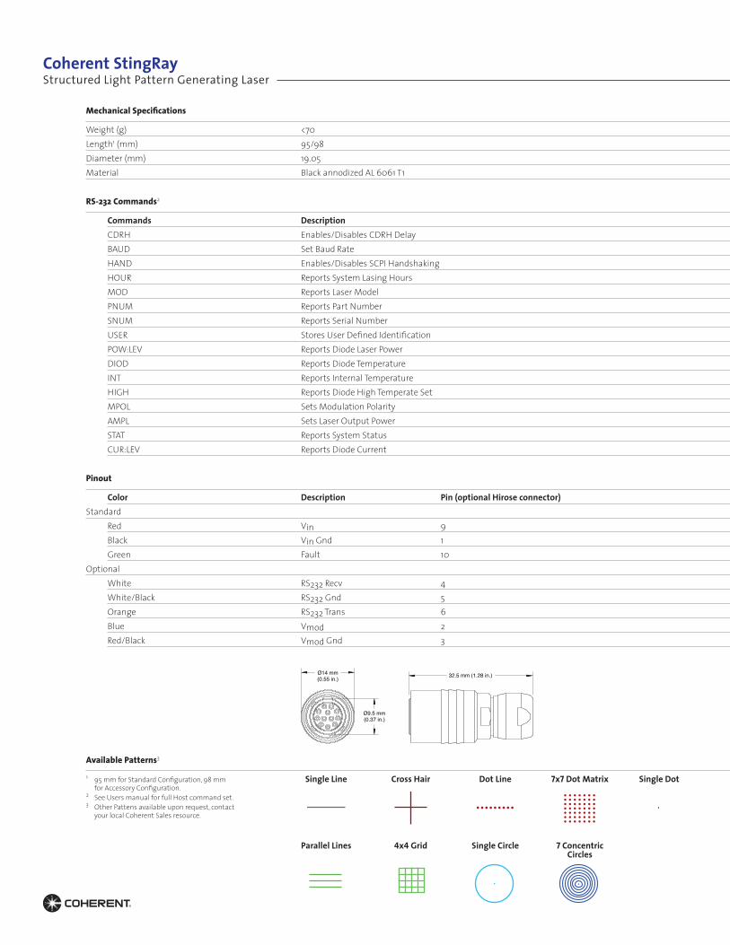
Weight (g) <70Length1 (mm) 95/98Diameter (mm) 19.05Material Black annodized AL 6061 T1 RS-232 Commands2
Commands Description CDRH Enables/Disables CDRH Delay BAUD Set Baud Rate HAND Enables/Disables SCPI Handshaking HOUR Reports System Lasing Hours MOD Reports Laser Model PNUM Reports Part Number SNUM Reports Serial Number USER Stores User Defined Identification POW:LEV Reports Diode Laser Power DIOD Reports Diode Temperature INT Reports Internal Temperature HIGH Reports Diode High Temperate Set MPOL Sets Modulation Polarity AMPL Sets Laser Output Power STAT Reports System Status CUR:LEV Reports Diode Current Pinout
Color Description Pin (optional Hirose connector)Standard Red Vin 9 Black Vin Gnd 1 Green Fault 10Optional White RS232 Recv 4 White/Black RS232 Gnd 5 Orange RS232 Trans 6 Blue Vmod 2 Red/Black Vmod Gnd 3 Available Patterns3
Single Line
Parallel Lines
Cross Hair
4x4 Grid
Dot Line
Single Circle
7x7 Dot Matrix
7 Concentric Circles
Single Dot1 95 mm for Standard Configuration, 98 mm for Accessory Configuration. 2 See Users manual for full Host command set. 3 Other Pattens available upon request, contact your local Coherent Sales resource.
32.5 mm (1.28 in.)Ø14 mm(0.55 in.)
Ø9.5 mm(0.37 in.)
Structured Light Pattern Generating LaserCoherent StingRay
Definitions
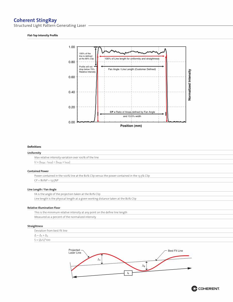
Uniformity Max relative intensity variation over 100% of the line U = (Imax - Imin) ÷ (Imax + Imin) Contained Power Power contained in the 100% line at the 80% Clip versus the power contained in the 13.5% Clip CP = 80%P ÷ 13.5%P Line Length / Fan Angle FA is the angle of the projection taken at the 80% Clip Line length is the physical length at a given working distance taken at the 80% Clip Relative Illumination Floor This is the minimum relative intensity at any point on the define line length Measured as a percent of the normalized intensity Straightness Deviation from best fit line ∆ = ∆1 + ∆2
S = (∆/L)*100
Flat-Top Intensity Profile
0.00
0.20
0.40
0.60
0.80
1.00
Nor
mal
ized
Inte
nsity
Position (mm)
Flat-Top Intensity Profile
Fan Angle / Line Length (Customer Defined)
CP = Ratio of Areas defined by Fan Angleand 13.5% width
100% of Line length for uniformity and straightness
100% of theline is definedat the 80% Clip
Profile will notdrop below 75%Relative Intensity
ProjectedLaser Line
Best Fit Line
L
1∆
2∆
Structured Light Pattern Generating LaserCoherent StingRay
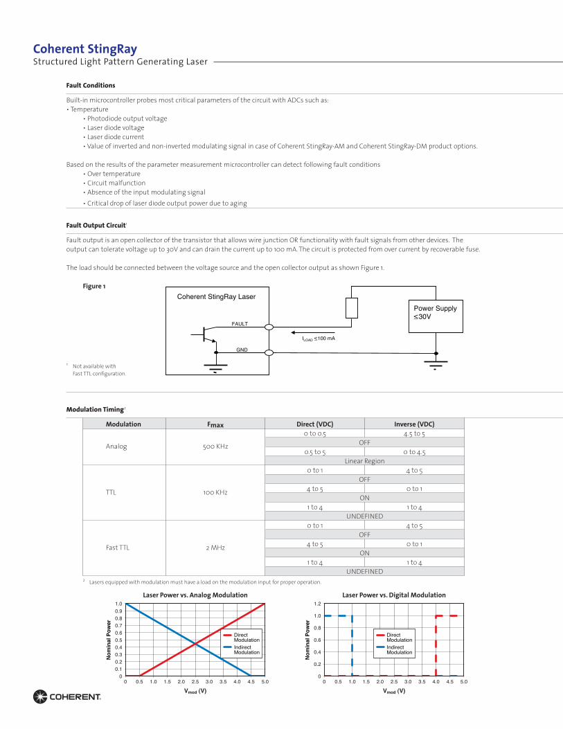
Fault Conditions
Built-in microcontroller probes most critical parameters of the circuit with ADCs such as: • Temperature • Photodiode output voltage • Laser diode voltage • Laser diode current • Value of inverted and non-inverted modulating signal in case of Coherent StingRay-AM and Coherent StingRay-DM product options.
Based on the results of the parameter measurement microcontroller can detect following fault conditions • Over temperature • Circuit malfunction • Absence of the input modulating signal • Critical drop of laser diode output power due to aging Fault Output Circuit1
Fault output is an open collector of the transistor that allows wire junction OR functionality with fault signals from other devices. Theoutput can tolerate voltage up to 30V and can drain the current up to 100 mA. The circuit is protected from over current by recoverable fuse.
The load should be connected between the voltage source and the open collector output as shown Figure 1. Figure 1
Modulation Timing2
Modulation Fmax Direct (VDC) Inverse (VDC)
Analog 500 KHz
0 to 0.5 4.5 to 5 OFF 0.5 to 5 0 to 4.5 Linear Region
TTL 100 KHz
0 to 1 4 to 5 OFF 4 to 5 0 to 1 ON 1 to 4 1 to 4 UNDEFINED
Fast TTL 2 MHz
0 to 1 4 to 5 OFF 4 to 5 0 to 1 ON 1 to 4 1 to 4 UNDEFINED
FAULT
GND
Coherent StingRay Laser Power Supply <_30V
ILOAD <_100 mA
Vmod (V)
Nom
inal
Pow
er
0
0.2
0.4
0.6
0.8
1.0
1.2
0 0.5 1.0 1.5 2.0 2.5 3.0 3.5 4.0 4.5 5.0
DirectModulationIndirectModulation
Laser Power vs. Analog Modulation Laser Power vs. Digital Modulation
Vmod (V)
Nom
inal
Pow
er
00.10.20.30.40.50.60.70.80.91.0
0 0.5 1.0 1.5 2.0 2.5 3.0 3.5 4.0 4.5 5.0
DirectModulationIndirectModulation
1 Not available with Fast TTL configuration.
2 Lasers equipped with modulation must have a load on the modulation input for proper operation.
Structured Light Pattern Generating LaserCoherent StingRay
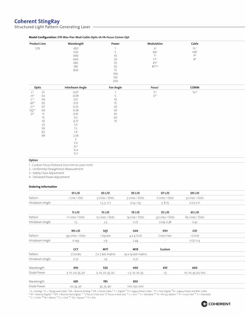
Model Configuration: STR-Wav-Pwr-Mod-Cable-Optic-IA-FA-Focus-Comm-Opt
Product Line Wavelength Power Modulation Cable STR 450 1 A1 FL2
520 5 RA3 HR4
640 10 T5 P6
660 20 FT7 B8
685 35 RT9
785 50 RFT10
830 75 100 150 200
Optic Interbeam Angle Fan Angle Focus11 COMM L12 01 0.07 1 S13 Tx14
H15 03 0.09 5 E16
C17 04 0.11 10 M18 05 0.15 15 G19 07 0.23 20SQ20 09 0.38 30 D21 11 0.41 45 15 0.5 60 19 0.77 75 33 1.11 59 1.5 65 1.9 99 2.34 5 5.4 9.7 11.4 11.7
Option 1 - Custom Focus Distance (100 mm to 2000 mm)2 - Uniformity/Straightness Measurement3 - Safety Class Adjustment4 - Delivered Power Adjustment Ordering Information
01 L/D 03 L/D 05 L/D 07 L/D 09 L/DPattern 1 Line / Dot 3 Lines / Dots 5 Lines / Dots 7 Lines / Dots 9 Lines / DotsIntrabeam Angle - 1.5, 5, 11.7 0.23, 1.55 5, 8.75 0.07, 0.11
11 L/D 15 L/D 19 L/D 33 L/D 65 L/DPattern 11 Lines / Dots 15 Lines / Dots 19 Line / Dots 33 Lines / Dots 65 Lines / DotsIntrabeam Angle 1.5 2.3 0.77 0.09, 0.38 0.41
99 L/D SQ1 G44 01H C01Pattern 99 Lines / Dots 1 Square 4 x 4 Grid Cross Hair 1 CircleIntrabeam Angle 0.149 2.9 2.44 - 0.77, 11.4
CC7 M77 M19 CustomPattern 7 Circles 7 x 7 dot matrix 19 x 19 dot matrix Intrabeam Angle 0.77 1.9 0.77 Wavelength 450 520 640 655 660Diode Power 5, 10 ,20, 35, 50 5, 10, 20, 35, 50 1, 5, 10, 20, 35 1,5 10, 20, 35, 50, 100 Wavelength 685 785 830Diode Power 20, 35, 50 35, 75, 90 100, 150, 2001 A = Analog. 2 FL = Flying Lead Cable. 3 RA = Reverse Analog. 4 HR = Hirose Cable. 5 T = Digital. 6 P = Legacy Power Cable. 7 FT = Fast Digital. 8 B = Legacy Power and BNC Cable. 9 RT = Reverse Digital. 10 RFT = Reverse Fast Digital. 11 ”S” focus is fast axis. “E” focus is slow axis. 12 L = Line. 13 S = Standard. 14 Tx = RS-232 Option. 15 H = Cross Hair. 16 E = Extended. 17 C = Circle. 18 M = Matrix. 19 G = Grid. 20 SQ = Square. 21 D = Dot.
Structured Light Pattern Generating LaserCoherent StingRay
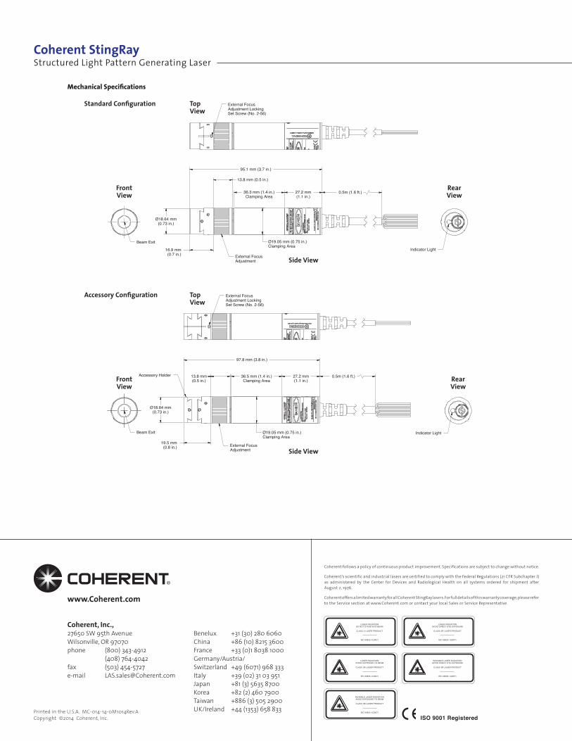
External FocusAdjustment
Indicator Light
Beam Exit
Accessory Holder
Ø19.05 mm (0.75 in.)Clamping Area
Ø18.64 mm(0.73 in.)
Ø18.64 mm(0.73 in.)
16.9 mm(0.7 in.)
External FocusAdjustment
Indicator LightBeam Exit Ø19.05 mm (0.75 in.)Clamping Area
36.5 mm (1.4 in.)Clamping Area
13.8 mm(0.5 in.)
27.2 mm(1.1 in.)
0.5m (1.6 ft.)
19.5 mm(0.8 in.)
36.3 mm (1.4 in.)Clamping Area
27.2 mm(1.1 in.)
External FocusAdjustment LockingSet Screw (No. 2-56)
External FocusAdjustment LockingSet Screw (No. 2-56)
95.1 mm (3.7 in.)
97.8 mm (3.8 in.)
0.5m (1.6 ft.)
13.8 mm (0.5 in.)
Mechanical Specifications
Side View
Standard Configuration Top View
FrontView
RearView
Side View
Accessory Configuration Top View
FrontView
RearView
Coherent follows a policy of continuous product improvement. Specifications are subject to change without notice.
Coherent’s scientific and industrial lasers are certified to comply with the Federal Regulations (21 CFR Subchapter J) as administered by the Center for Devices and Radiological Health on all systems ordered for shipment after August 2, 1976.
Coherent offers a limited warranty for all Coherent StingRay lasers. For full details of this warranty coverage, please refer to the Service section at www.Coherent.com or contact your local Sales or Service Representative.
LASER RADIATIONDO NOT STARE INTO BEAM
CLASS 2 LASER PRODUCT
IEC 60825-1(2007)
LASER RADIATIONAVOID EXPOSURE TO BEAM
CLASS 3B LASER PRODUCT
IEC 60825-1(2007)
INVISIBLE LASER RADIATIONAVOID EXPOSURE TO BEAM
CLASS 3B LASER PRODUCT
IEC 60825-1(2007)
LASER RADIATIONAVOID DIRECT EYE EXPOSURE
CLASS 3R LASER PRODUCT
IEC 60825-1(2007)
INVISIBLE LASER RADIATIONAVOID DIRECT EYE EXPOSURE
CLASS 3R LASER PRODUCT
IEC 60825-1(2007)
Benelux +31 (30) 280 6060China +86 (10) 8215 3600France +33 (0)1 8038 1000Germany/Austria/Switzerland +49 (6071) 968 333Italy +39 (02) 31 03 951Japan +81 (3) 5635 8700Korea +82 (2) 460 7900Taiwan +886 (3) 505 2900UK/Ireland +44 (1353) 658 833
www.Coherent.com
Coherent, Inc.,27650 SW 95th AvenueWilsonville, OR 97070phone (800) 343-4912 (408) 764-4042fax (503) 454-5727e-mail [email protected]
Printed in the U.S.A. MC-014-14-0M1014Rev.ACopyright ©2014 Coherent, Inc. ISO 9001 Registered
Structured Light Pattern Generating LaserCoherent StingRay