Clamp-On Ground Resistance Tester Models 3711 and 3731 · Ground Resistance Tester Models 3711 and...
40
Clamp-On Ground Resistance Tester Models 3711 and 3731 USER MANUAL Ω Ω
Transcript of Clamp-On Ground Resistance Tester Models 3711 and 3731 · Ground Resistance Tester Models 3711 and...
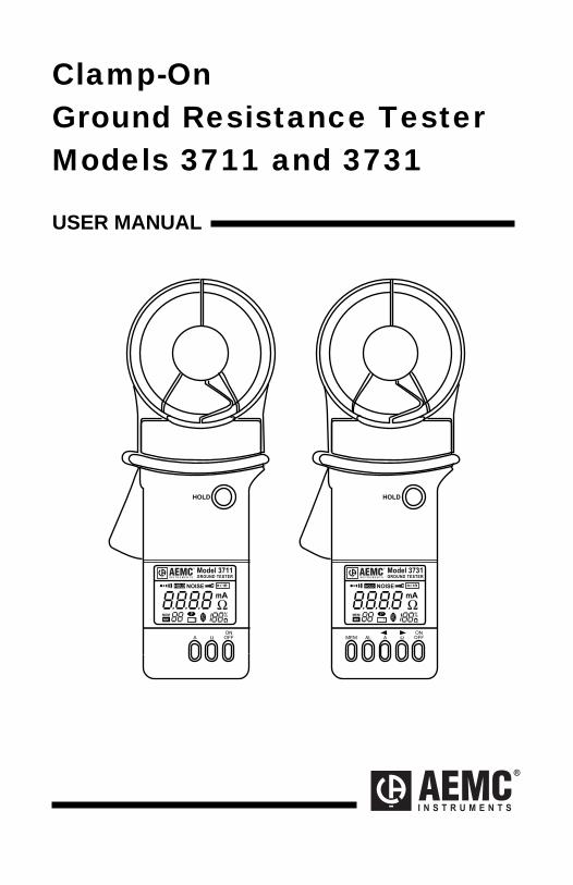
Clamp-On Ground Resistance Tester Models 3711 and 3731 USER MANUAL
����
��
��
����
���
�
����
����� ����� � �����
� ��
���
����
��
����
���
�
����
��� �� � ��
���
�
� � � � � � � �
����� ������ � �����
�
� � � � � � � �
��
Statement of Compliance
Chauvin Arnoux®, Inc. d.b.a. AEMC® Instruments certifies that this instrument has been calibrated using standards and instruments traceable to international standards.
We guarantee that at the time of shipping your instrument has met its published specifications.
An NIST traceable certificate may be requested at the time of purchase, or obtained by returning the instrument to our repair and calibration facility, for a nominal charge.
The recommended calibration interval for this instrument is 12 months and begins on the date of receipt by the customer. For recalibration, please use our calibration services. Refer to our repair and calibration section at www.aemc.com.
Serial #:
Catalog #: 2117.60/2117.61
Model #: 3711/3731
Please fill in the appropriate date as indicated:
Date Received:
Date Calibration Due:
Chauvin Arnoux®, Inc.d.b.a AEMC® Instrumentswww.aemc.com

Limited Warranty The Models 3711 and 3731 are warranted to the owner for a period of two years from the date of original purchase against defects in manufacture. This limited warranty is given by AEMC® Instruments, not by the distributor from whom it was purchased. This warranty is void if the unit has been tampered with, abused or if the defect is related to service not performed by AEMC® Instruments.
For full and detailed warranty coverage, please read the Warranty Coverage Information, which is attached to the Warranty Registration Card (if enclosed) or is available at www.aemc.com. Please keep the Warranty Coverage Information with your records.
What AEMC® Instruments will do:
If a malfunction occurs within the warranty period, you may return the instrument to us for repair, provided we have your warranty registration information on file or a proof of purchase. AEMC® Instruments will, at its option, repair or replace the faulty material.
YOU CAN NOW REGISTER ONLINE AT: www.aemc.com
Warranty Repairs What you must do to return an Instrument for Warranty Repair:
First, request a Customer Service Authorization Number (CSA#) by phone or by fax from our Service Department (see address below), then return the instrument along with the signed CSA Form. Please write the CSA# on the outside of the shipping container. Return the instrument, postage or shipment pre-paid to:
Chauvin Arnoux®, Inc. d.b.a. AEMC® Instruments 15 Faraday Drive • Dover, NH 03820 USA Tel: (800) 945-2362 (Ext. 360)
(603) 749-6434 (Ext. 360) Fax: (603) 742-2346 or (603) 749-6309
Caution: To protect yourself against in-transit loss, we recommend you insure your returned material.
NOTE: All customers must obtain a CSA# before returning any instrument.
Table of Contents
Warning ..................................................................................................... 4
International Electrical Symbols ................................................................ 4
Definition of Measurement Categories ...................................................... 5
Receiving Your Shipment .......................................................................... 5 Packaging .................................................................................................. 5 Accessories ............................................................................................... 5 Important Information - Proper Operation ................................................. 5 Description ................................................................................................ 6
Product Construction ............................................................................. 6 Jaw Design ............................................................................................ 7 Body Design .......................................................................................... 7
Electrical Specifications ............................................................................ 8 Ground Resistance ................................................................................ 8 Ground or Leakage Current................................................................... 8
Mechanical Specifications ......................................................................... 8 Safety Specifications ................................................................................. 9 Model 3711 Controls ............................................................................... 10 Model 3731 Controls ............................................................................... 11 Digital Display Features .......................................................................... 12
Additional Features of the Model 3731 ................................................ 13 Function Controls .................................................................................... 14
On/Off .................................................................................................. 14 Auto-Off ............................................................................................... 15 Hold ..................................................................................................... 15 Beeper Disable .................................................................................... 15 Resistance ........................................................................................... 15 Resistance ........................................................................................... 16 Current ................................................................................................. 17 Alarm ................................................................................................... 18 Programming the Alarm Setpoint ........................................................ 18 Changing the Alarm Trigger ................................................................ 19 Memory ................................................................................................ 19 Memory ................................................................................................ 20 Memory Recall ..................................................................................... 20 Clear Memory ...................................................................................... 20
Function Access Summary ..................................................................... 21
Programming Summary .......................................................................... 21 Principle of Operation .............................................................................. 22 Field Applications .................................................................................... 24
Pole Ground Rods ............................................................................... 24 Service Entrance or Meter ................................................................... 25 Pad Mounted Transformer ................................................................... 25 Pad Mounted Transformer ................................................................... 26 Transmission Towers .......................................................................... 27 Central Office Locations ...................................................................... 27 Service Panel ...................................................................................... 28 Phone Pedestal ................................................................................... 29 Above Telephone Space ..................................................................... 31 General Measurement Notes .............................................................. 31
Operating Reference Card ...................................................................... 32 Field Test Loop........................................................................................ 32 Commonly Asked Questions for.............................................................. 33 Clamp-on Ground Resistance Measurements ........................................ 33 Maintenance ............................................................................................ 34 Battery Replacement Procedure ............................................................. 35 Troubleshooting ...................................................................................... 35 Repair and Calibration ............................................................................ 36
Technical and Sales Assistance ............................................................. 36
Ground Resistance Tester Models 3711 and 3731
- 4 -
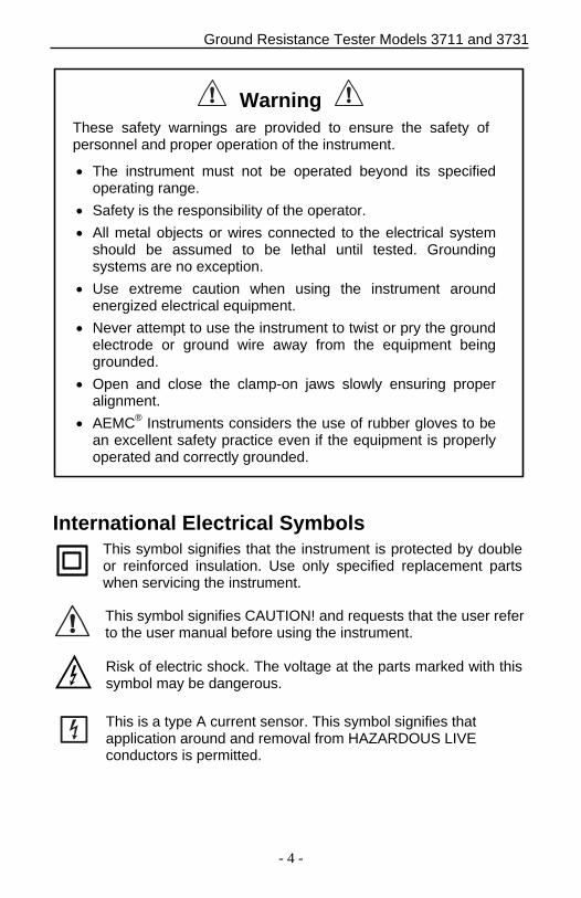
Warning These safety warnings are provided to ensure the safety of personnel and proper operation of the instrument.
The instrument must not be operated beyond its specifiedoperating range.
Safety is the responsibility of the operator.
All metal objects or wires connected to the electrical systemshould be assumed to be lethal until tested. Groundingsystems are no exception.
Use extreme caution when using the instrument aroundenergized electrical equipment.
Never attempt to use the instrument to twist or pry the groundelectrode or ground wire away from the equipment beinggrounded.
Open and close the clamp-on jaws slowly ensuring properalignment.
AEMC® Instruments considers the use of rubber gloves to bean excellent safety practice even if the equipment is properlyoperated and correctly grounded.
International Electrical Symbols This symbol signifies that the instrument is protected by double or reinforced insulation. Use only specified replacement parts when servicing the instrument.
This symbol signifies CAUTION! and requests that the user refer to the user manual before using the instrument.
Risk of electric shock. The voltage at the parts marked with this symbol may be dangerous.
This is a type A current sensor. This symbol signifies that application around and removal from HAZARDOUS LIVE conductors is permitted.
Ground Resistance Tester Models 3711 and 3731
- 5 -
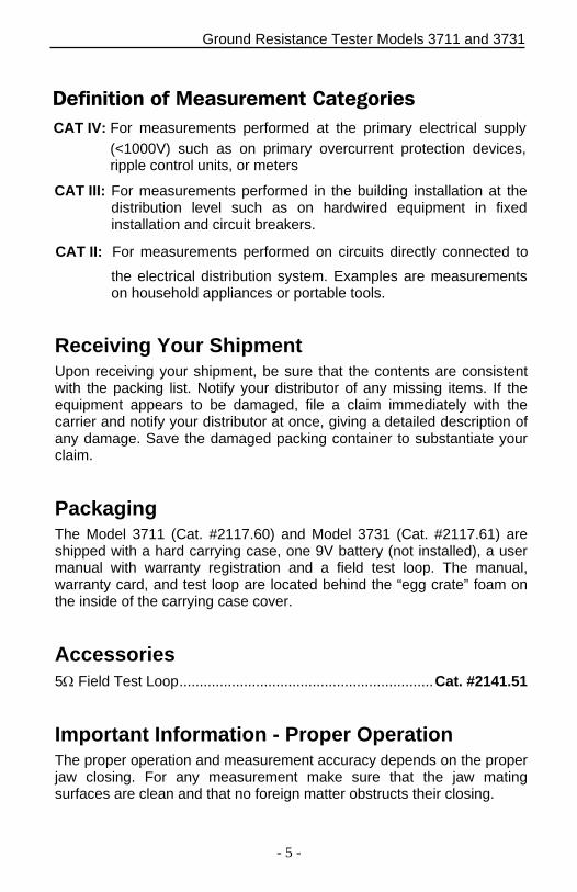
Definition of Measurement Categories
CAT II: For measurements performed on circuits directly connected to
the electrical distribution system. Examples are measurements on household appliances or portable tools.
CAT III: For measurements performed in the building installation at the distribution level such as on hardwired equipment in fixed installation and circuit breakers.
CAT IV: For measurements performed at the primary electrical supply
(<1000V) such as on primary overcurrent protection devices, ripple control units, or meters
Receiving Your Shipment Upon receiving your shipment, be sure that the contents are consistent with the packing list. Notify your distributor of any missing items. If the equipment appears to be damaged, file a claim immediately with the carrier and notify your distributor at once, giving a detailed description of any damage. Save the damaged packing container to substantiate your claim.
Packaging The Model 3711 (Cat. #2117.60) and Model 3731 (Cat. #2117.61) are shipped with a hard carrying case, one 9V battery (not installed), a user manual with warranty registration and a field test loop. The manual, warranty card, and test loop are located behind the “egg crate” foam on the inside of the carrying case cover.
Accessories 5 Field Test Loop ............................................................... Cat. #2141.51
Important Information - Proper Operation The proper operation and measurement accuracy depends on the proper jaw closing. For any measurement make sure that the jaw mating surfaces are clean and that no foreign matter obstructs their closing.

Ground Resistance Tester Models 3711 and 3731
- 6 -
Description
The Ground Resistance Tester, Models 3711 and 3731, measure ground rod and small grid resistance through any season, without the use of auxiliary ground rods. Clamp-on ground resistance testers are used in multi-grounded systems without disconnecting the ground under test. The Models 3711 and 3731 simply clamp around the ground conductor or rod and measure the resistance to ground. By performing measurements on intact ground systems, the user also verifies the quality of the grounding connections and bonds. Resistance and continuity of grounding loops around pads and buildings may also be measured.
Both models include a current measurement function. The probe’s high sensitivity enables measurement of leakage current flowing to ground or circulating in ground loops down to 1mA and neutral currents to 30Arms. This feature provides additional information which is becoming vital as distribution ground networks carry higher levels of noise and harmonics which affect power quality.
Both models offer battery life information at power-up and Auto-Off for power management. Additional features are also displayed on the large LCD to ensure precise measurements. The Buzzer and Auto-Off features may be disabled from the push-buttons at any time.
The Model 3731 offers an Alarm function and a Memory (logging) function. In the Alarm mode, the probe will audibly and visually indicate if the reading is beyond an input set point. The user may also have the Alarm initiated above or below the set point. This Alarm feature permits quick field checks where only “pass” or “fail” readings will suffice.
The Memory function logs up to 99 measurements (Ohms or Amperes). This enables the user to conduct field surveys, and to retrieve and analyze the readings at a later time. The alarm settings and stored memory information are saved when the ground tester is turned off.
Product Construction
The Models 3711 and 3731 body cases are built of Lexan® for rugged use. The probe heads are encapsulated in a double-walled Lexan® shell (or equivalent polycarbonate) for extra strength and are reinforced at the body interfaces for enhanced field reliability. Overall construction and mechanical design ratings such as drop test, shock and vibration, weatherproofing against water projections, meet or exceed IEC (International Electrotechnical Commission) standards. The products have also been designed to meet EN 61010.
Ground Resistance Tester Models 3711 and 3731
- 7 -
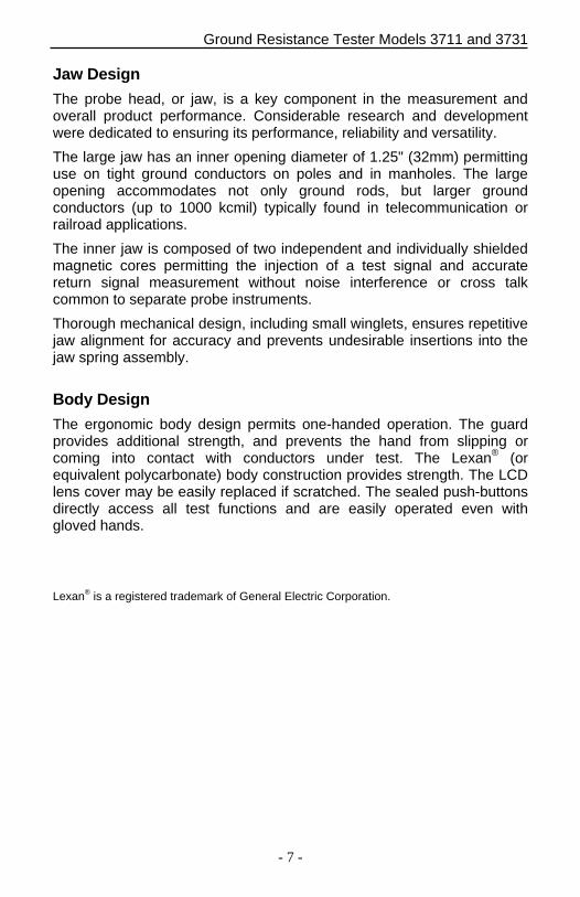
Jaw Design
The probe head, or jaw, is a key component in the measurement and overall product performance. Considerable research and development were dedicated to ensuring its performance, reliability and versatility.
The large jaw has an inner opening diameter of 1.25" (32mm) permitting use on tight ground conductors on poles and in manholes. The large opening accommodates not only ground rods, but larger ground conductors (up to 1000 kcmil) typically found in telecommunication or railroad applications.
The inner jaw is composed of two independent and individually shielded magnetic cores permitting the injection of a test signal and accurate return signal measurement without noise interference or cross talk common to separate probe instruments.
Thorough mechanical design, including small winglets, ensures repetitive jaw alignment for accuracy and prevents undesirable insertions into the jaw spring assembly.
Body Design
The ergonomic body design permits one-handed operation. The guard provides additional strength, and prevents the hand from slipping or coming into contact with conductors under test. The Lexan® (or equivalent polycarbonate) body construction provides strength. The LCD lens cover may be easily replaced if scratched. The sealed push-buttons directly access all test functions and are easily operated even with gloved hands.
Lexan® is a registered trademark of General Electric Corporation.
Ground Resistance Tester Models 3711 and 3731
- 8 -
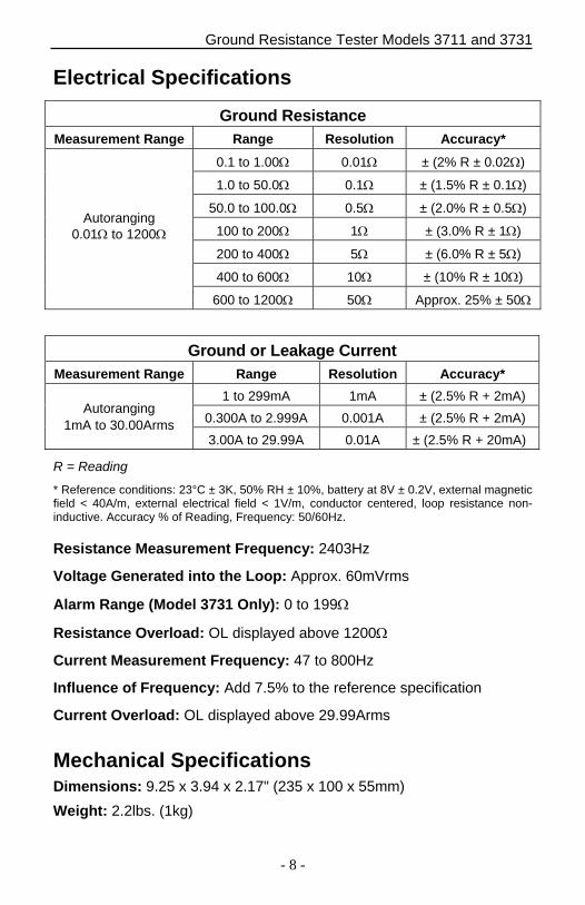
Electrical Specifications
Ground Resistance Measurement Range Range Resolution Accuracy*
Autoranging 0.01 to 1200
0.1 to 1.00 0.01 ± (2% R ± 0.02)
1.0 to 50.0 0.1 ± (1.5% R ± 0.1)
50.0 to 100.0 0.5 ± (2.0% R ± 0.5)
100 to 200 1 ± (3.0% R ± 1)
200 to 400 5 ± (6.0% R ± 5)
400 to 600 10 ± (10% R ± 10)
600 to 1200 50 Approx. 25% ± 50
Ground or Leakage Current Measurement Range Range Resolution Accuracy*
Autoranging 1mA to 30.00Arms
1 to 299mA 1mA ± (2.5% R + 2mA)
0.300A to 2.999A 0.001A ± (2.5% R + 2mA)
3.00A to 29.99A 0.01A ± (2.5% R + 20mA)
R = Reading
* Reference conditions: 23°C ± 3K, 50% RH ± 10%, battery at 8V ± 0.2V, external magneticfield < 40A/m, external electrical field < 1V/m, conductor centered, loop resistance non-inductive. Accuracy % of Reading, Frequency: 50/60Hz.
Resistance Measurement Frequency: 2403Hz
Voltage Generated into the Loop: Approx. 60mVrms
Alarm Range (Model 3731 Only): 0 to 199
Resistance Overload: OL displayed above 1200
Current Measurement Frequency: 47 to 800Hz
Influence of Frequency: Add 7.5% to the reference specification
Current Overload: OL displayed above 29.99Arms
Mechanical Specifications Dimensions: 9.25 x 3.94 x 2.17" (235 x 100 x 55mm)
Weight: 2.2lbs. (1kg)
Ground Resistance Tester Models 3711 and 3731
- 9 -
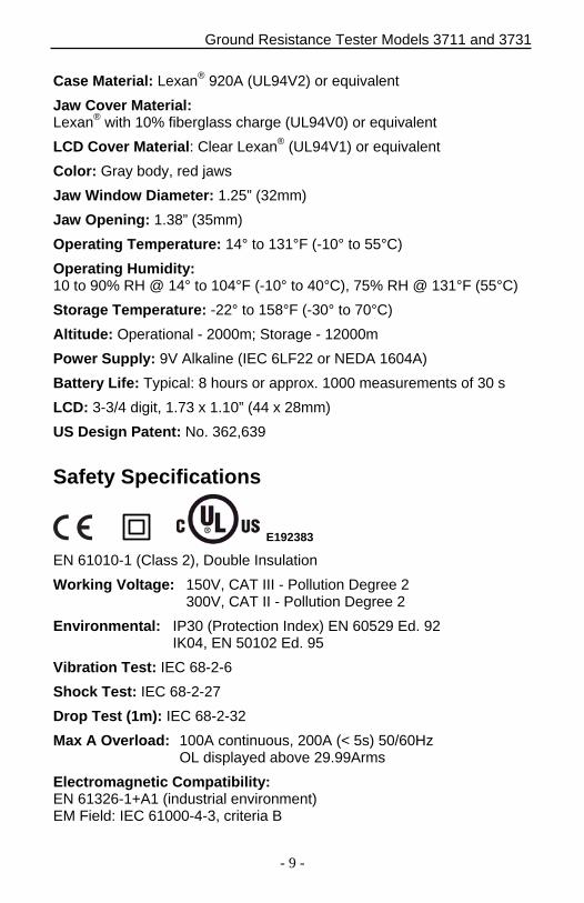
Case Material: Lexan® 920A (UL94V2) or equivalent
Jaw Cover Material: Lexan® with 10% fiberglass charge (UL94V0) or equivalent
LCD Cover Material: Clear Lexan® (UL94V1) or equivalent
Color: Gray body, red jaws
Jaw Window Diameter: 1.25” (32mm)
Jaw Opening: 1.38” (35mm)
Operating Temperature: 14° to 131°F (-10° to 55°C)
Operating Humidity: 10 to 90% RH @ 14° to 104°F (-10° to 40°C), 75% RH @ 131°F (55°C)
Storage Temperature: -22° to 158°F (-30° to 70°C)
Altitude: Operational - 2000m; Storage - 12000m
Power Supply: 9V Alkaline (IEC 6LF22 or NEDA 1604A)
Battery Life: Typical: 8 hours or approx. 1000 measurements of 30 s
LCD: 3-3/4 digit, 1.73 x 1.10” (44 x 28mm)
US Design Patent: No. 362,639
Safety Specifications
E192383
EN 61010-1 (Class 2), Double Insulation
Working Voltage: 150V, CAT III - Pollution Degree 2 300V, CAT II - Pollution Degree 2
Environmental: IP30 (Protection Index) EN 60529 Ed. 92 IK04, EN 50102 Ed. 95
Vibration Test: IEC 68-2-6
Shock Test: IEC 68-2-27
Drop Test (1m): IEC 68-2-32
Max A Overload: 100A continuous, 200A (< 5s) 50/60Hz OL displayed above 29.99Arms
Electromagnetic Compatibility: EN 61326-1+A1 (industrial environment) EM Field: IEC 61000-4-3, criteria B
Ground Resistance Tester Models 3711 and 3731
- 10 -
Model 3711 Controls
����
�
�
��
����
���
�
����
� ��
���
�
�
�
�
��
����� ����� � �����
�
� ����� ��
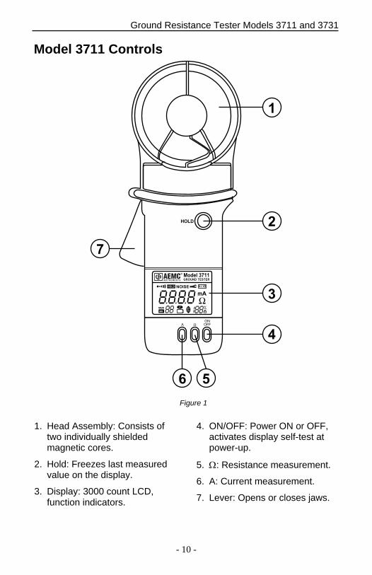
1. Head Assembly: Consists of two individually shielded magnetic cores.
2. Hold: Freezes last measured value on the display.
3. Display: 3000 count LCD, function indicators.
4. ON/OFF: Power ON or OFF, activates display self-test at power-up.
5. : Resistance measurement.
6. A: Current measurement.
7. Lever: Opens or closes jaws.
Figure 1
Ground Resistance Tester Models 3711 and 3731
- 11 -
Model 3731 Controls
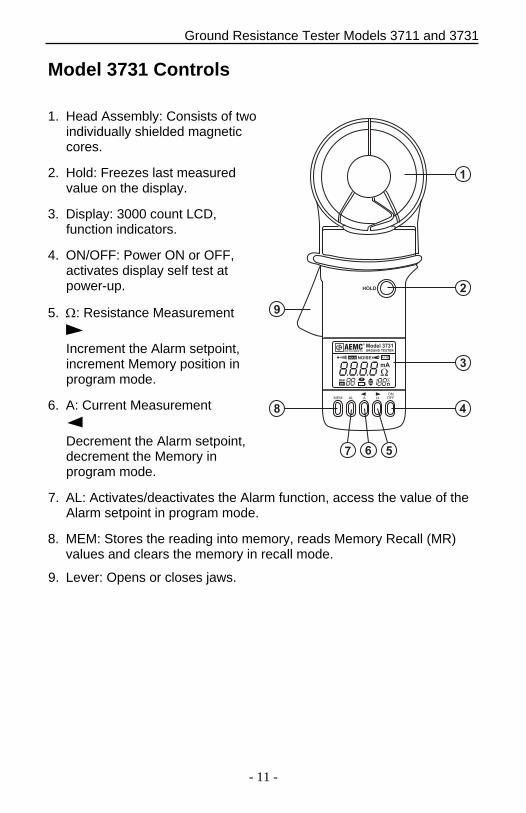
1. Head Assembly: Consists of two individually shielded magnetic cores.
2. Hold: Freezes last measured value on the display.
3. Display: 3000 count LCD, function indicators.
4. ON/OFF: Power ON or OFF, activates display self test at power-up.
5. : Resistance Measurement
Increment the Alarm setpoint, increment Memory position in program mode.
6. A: Current Measurement
Decrement the Alarm setpoint, decrement the Memory in program mode.
7. AL: Activates/deactivates the Alarm function, access the value of the Alarm setpoint in program mode.
8. MEM: Stores the reading into memory, reads Memory Recall (MR) values and clears the memory in recall mode.
9. Lever: Opens or closes jaws.
HOLD
+
–
mA
R 1HOLD
MEM
MR
NOISE
MEM AL A ΩON
OFF
Model 3731GROUND TESTER
®
I N S T R U M E N T S
1
2
3
48
567
9
Ground Resistance Tester Models 3711 and 3731
- 12 -
Digital Display Features
�
�
��
� ����
� �
��
���
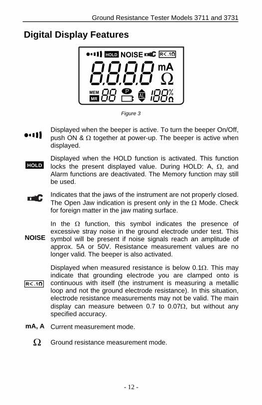
Displayed when the beeper is active. To turn the beeper On/Off, push ON & together at power-up. The beeper is active when displayed.
Displayed when the HOLD function is activated. This function locks the present displayed value. During HOLD: A, , and Alarm functions are deactivated. The Memory function may still be used.
Indicates that the jaws of the instrument are not properly closed. The Open Jaw indication is present only in the Mode. Check for foreign matter in the jaw mating surface.
In the function, this symbol indicates the presence of excessive stray noise in the ground electrode under test. This symbol will be present if noise signals reach an amplitude of approx. 5A or 50V. Resistance measurement values are no longer valid. The beeper is also activated.
Displayed when measured resistance is below 0.1. This may indicate that grounding electrode you are clamped onto is continuous with itself (the instrument is measuring a metallic loop and not the ground electrode resistance). In this situation, electrode resistance measurements may not be valid. The main display can measure between 0.7 to 0.07, but without any specified accuracy.
Current measurement mode.
Ground resistance measurement mode.
Figure 3
����
NOISE
mA, A
� ��
Ground Resistance Tester Models 3711 and 3731
- 13 -
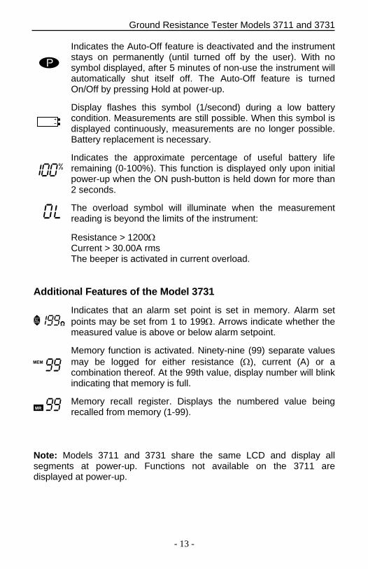
Indicates the Auto-Off feature is deactivated and the instrument stays on permanently (until turned off by the user). With no symbol displayed, after 5 minutes of non-use the instrument will automatically shut itself off. The Auto-Off feature is turned On/Off by pressing Hold at power-up.
Display flashes this symbol (1/second) during a low battery condition. Measurements are still possible. When this symbol is displayed continuously, measurements are no longer possible. Battery replacement is necessary.
Indicates the approximate percentage of useful battery life remaining (0-100%). This function is displayed only upon initial power-up when the ON push-button is held down for more than 2 seconds.
The overload symbol will illuminate when the measurement reading is beyond the limits of the instrument:
Resistance > 1200 Current > 30.00A rms The beeper is activated in current overload.
Additional Features of the Model 3731
Indicates that an alarm set point is set in memory. Alarm set points may be set from 1 to 199. Arrows indicate whether the measured value is above or below alarm setpoint.
Memory function is activated. Ninety-nine (99) separate values may be logged for either resistance (), current (A) or a combination thereof. At the 99th value, display number will blink indicating that memory is full.
Memory recall register. Displays the numbered value being recalled from memory (1-99).
Note: Models 3711 and 3731 share the same LCD and display all segments at power-up. Functions not available on the 3711 are displayed at power-up.
���
��
Ground Resistance Tester Models 3711 and 3731
- 14 -
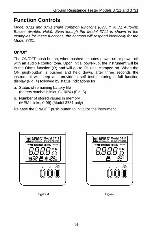
Function Controls Model 3711 and 3731 share common functions (On/Off, A, , Auto-off, Buzzer disable, Hold). Even though the Model 3711 is shown in the examples for these functions, the controls will respond identically for the Model 3731.
On/Off
The ON/OFF push-button, when pushed actuates power on or power off with an audible control tone. Upon initial power-up, the instrument will be in the Ohms function () and will go to OL until clamped on. When the ON push-button is pushed and held down, after three seconds the instrument will beep and provide a self test featuring a full function display (Fig. 4) followed by status indications for:
a. Status of remaining battery life (battery symbol blinks, 0-100%) (Fig. 5)
b. Number of stored values in memory (MEM blinks, 0-99) (Model 3731 only)
Release the ON/OFF push-button to initialize the instrument.
�
�
��
� �� � ����
� �
��
���
� ��
���
�
�
��
�� ���
� ��
���
����� ��������� � �� �
�
������� ���
����� ��������� � �� �
�
������� ���
Figure 4 Figure 5
Ground Resistance Tester Models 3711 and 3731
- 15 -
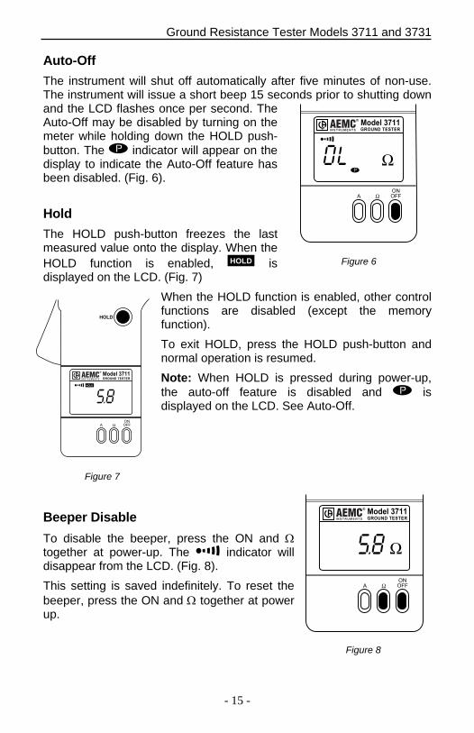
Auto-Off
The instrument will shut off automatically after five minutes of non-use. The instrument will issue a short beep 15 seconds prior to shutting down and the LCD flashes once per second. The Auto-Off may be disabled by turning on the meter while holding down the HOLD push-button. The indicator will appear on the display to indicate the Auto-Off feature has been disabled. (Fig. 6).
Hold
The HOLD push-button freezes the last measured value onto the display. When the HOLD function is enabled, ���� is displayed on the LCD. (Fig. 7)
When the HOLD function is enabled, other control functions are disabled (except the memory function).
To exit HOLD, press the HOLD push-button and normal operation is resumed.
Note: When HOLD is pressed during power-up, the auto-off feature is disabled and is displayed on the LCD. See Auto-Off.
Beeper Disable
To disable the beeper, press the ON and together at power-up. The indicator will disappear from the LCD. (Fig. 8).
This setting is saved indefinitely. To reset the beeper, press the ON and together at power up.
Figure 6
� ��
���
����� ���� �� ������
�
����� �����
� ��
���
����� ���� �� ������
�
����� �����
Figure 7
����
� ��
���
����
���� �� ������ ������
�
�����������
Figure 8
Ground Resistance Tester Models 3711 and 3731
- 16 -
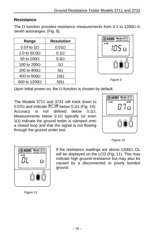
Resistance
The function provides resistance measurements from 0.1 to 1200 in seven autoranges. (Fig. 9).
Range Resolution
0.07 to 1 0.01
1.0 to 50.0 0.1
50 to 100 0.5
100 to 200 1
200 to 400 5
400 to 600 10
600 to 1200 50
Upon initial power-on, the function is chosen by default.
The Models 3711 and 3731 will track down to 0.07 and indicate � �� below 0.1 (Fig. 10). Accuracy is not defined below 0.1. Measurements below 0.1 typically (or even 1) indicate the ground tester is clamped onto a closed loop and that the signal is not flowing through the ground under test.
If the resistance readings are above 1200, OL will be displayed on the LCD (Fig. 11). This may indicate high ground resistance but may also be caused by a disconnected or poorly bonded ground.
Figure 9
Figure 10
Figure 11
�
��
���
����� ���� �� ������
�
����� �����
� ��
���
� ��
����� ����� ��� ������
�
�����������
A ΩONOFF
����� ���� �� ������
�
����� �����
Ground Resistance Tester Models 3711 and 3731
- 17 -
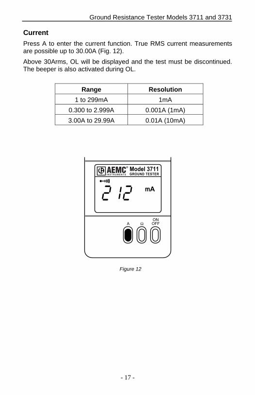
Current
Press A to enter the current function. True RMS current measurements are possible up to 30.00A (Fig. 12).
Above 30Arms, OL will be displayed and the test must be discontinued. The beeper is also activated during OL.
Range Resolution
1 to 299mA 1mA
0.300 to 2.999A 0.001A (1mA)
3.00A to 29.99A 0.01A (10mA)
��
� ��
���
����� ��� ���� �����
�
���� ������
Figure 12
Ground Resistance Tester Models 3711 and 3731
- 18 -
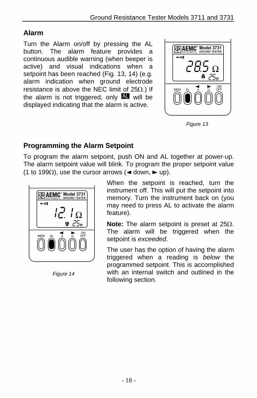
Alarm
Turn the Alarm on/off by pressing the AL button. The alarm feature provides a continuous audible warning (when beeper is active) and visual indications when a setpoint has been reached (Fig. 13, 14) (e.g. alarm indication when ground electrode resistance is above the NEC limit of 25.) If the alarm is not triggered, only will be displayed indicating that the alarm is active.
Programming the Alarm Setpoint
To program the alarm setpoint, push ON and AL together at power-up. The alarm setpoint value will blink. To program the proper setpoint value (1 to 199), use the cursor arrows ( down, up).
When the setpoint is reached, turn the instrument off. This will put the setpoint into memory. Turn the instrument back on (you may need to press AL to activate the alarm feature).
Note: The alarm setpoint is preset at 25. The alarm will be triggered when the setpoint is exceeded.
The user has the option of having the alarm triggered when a reading is below the programmed setpoint. This is accomplished with an internal switch and outlined in the following section.
Figure 13
Figure 14
����� ����� �� ������
�
����� �����
��� �� � ��
���
��� �� � ��
���
����� ����� �� ������
�
����� �����
Ground Resistance Tester Models 3711 and 3731
- 19 -
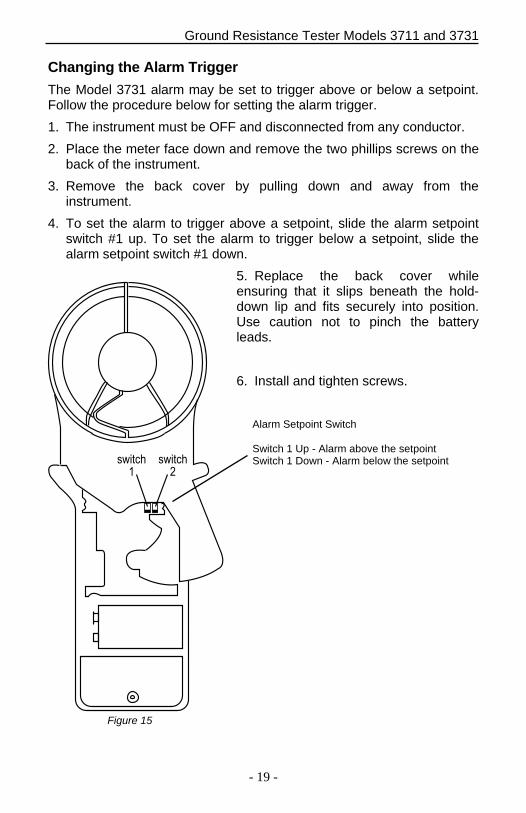
Changing the Alarm Trigger
The Model 3731 alarm may be set to trigger above or below a setpoint. Follow the procedure below for setting the alarm trigger.
1. The instrument must be OFF and disconnected from any conductor.
2. Place the meter face down and remove the two phillips screws on theback of the instrument.
3. Remove the back cover by pulling down and away from theinstrument.
4. To set the alarm to trigger above a setpoint, slide the alarm setpointswitch #1 up. To set the alarm to trigger below a setpoint, slide thealarm setpoint switch #1 down.
5. Replace the back cover whileensuring that it slips beneath the hold-down lip and fits securely into position. Use caution not to pinch the battery leads.
6. Install and tighten screws.
������
�
������
�
Alarm Setpoint Switch
Switch 1 Up - Alarm above the setpoint Switch 1 Down - Alarm below the setpoint
Figure 15
Ground Resistance Tester Models 3711 and 3731
- 20 -
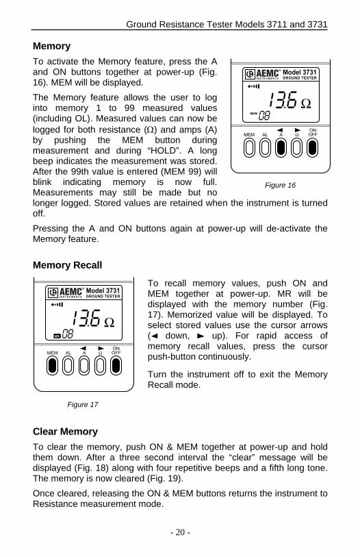
Memory
To activate the Memory feature, press the A and ON buttons together at power-up (Fig. 16). MEM will be displayed.
The Memory feature allows the user to log into memory 1 to 99 measured values (including OL). Measured values can now be logged for both resistance () and amps (A) by pushing the MEM button during measurement and during “HOLD”. A long beep indicates the measurement was stored. After the 99th value is entered (MEM 99) will blink indicating memory is now full. Measurements may still be made but no longer logged. Stored values are retained when the instrument is turned off.
Pressing the A and ON buttons again at power-up will de-activate the Memory feature.
Memory Recall
To recall memory values, push ON and MEM together at power-up. MR will be displayed with the memory number (Fig. 17). Memorized value will be displayed. To select stored values use the cursor arrows ( down, up). For rapid access of memory recall values, press the cursor push-button continuously.
Turn the instrument off to exit the Memory Recall mode.
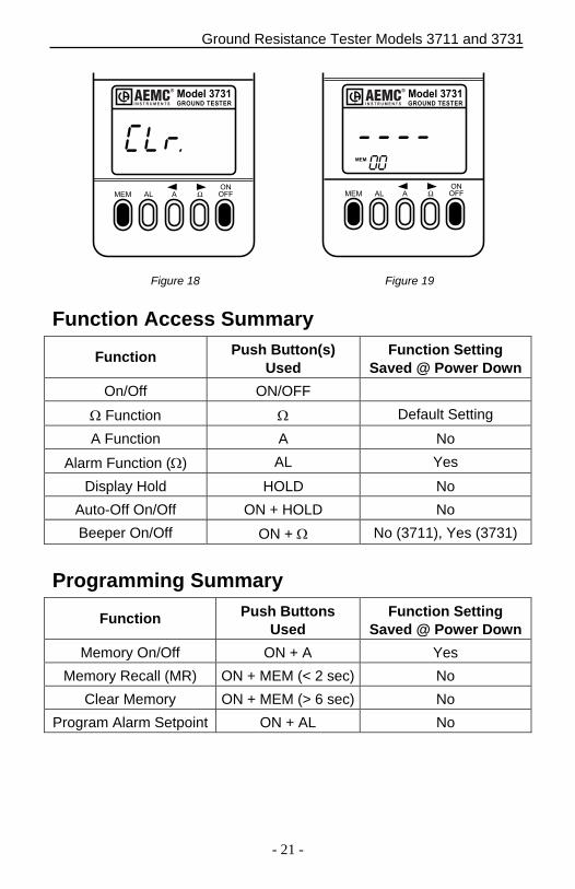
Clear Memory
To clear the memory, push ON & MEM together at power-up and hold them down. After a three second interval the “clear” message will be displayed (Fig. 18) along with four repetitive beeps and a fifth long tone. The memory is now cleared (Fig. 19).
Once cleared, releasing the ON & MEM buttons returns the instrument to Resistance measurement mode.
Figure 16
Figure 17
����� ����� �� ������
�
����� �����
���
��� �� � ��
���
����� ����� �� ������
�
����� �����
��
��� �� � ��
���
Ground Resistance Tester Models 3711 and 3731
- 21 -
��� �� � ��
���
���
��� �� � ��
���
����� ���� ��� ������
�
�����������
����� ���� ��� ������
�
�����������
Function Access Summary
Function Push Button(s) Used
Function Setting Saved @ Power Down
On/Off ON/OFF
Function Default Setting
A Function A No
Alarm Function () AL Yes
Display Hold HOLD No
Auto-Off On/Off ON + HOLD No
Beeper On/Off ON + No (3711), Yes (3731)
Programming Summary
Function Push Buttons Used
Function Setting Saved @ Power Down
Memory On/Off ON + A Yes
Memory Recall (MR) ON + MEM (< 2 sec) No
Clear Memory ON + MEM (> 6 sec) No
Program Alarm Setpoint ON + AL No
Figure 18 Figure 19
Ground Resistance Tester Models 3711 and 3731
- 22 -
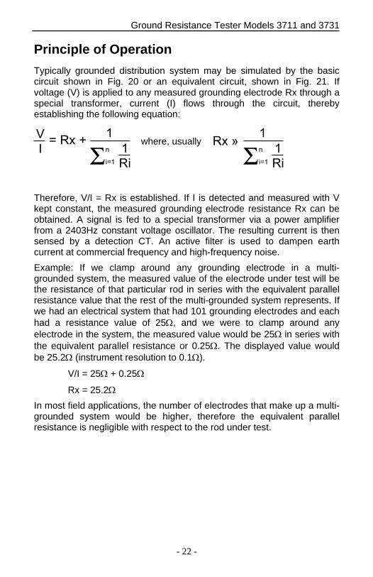
Principle of Operation
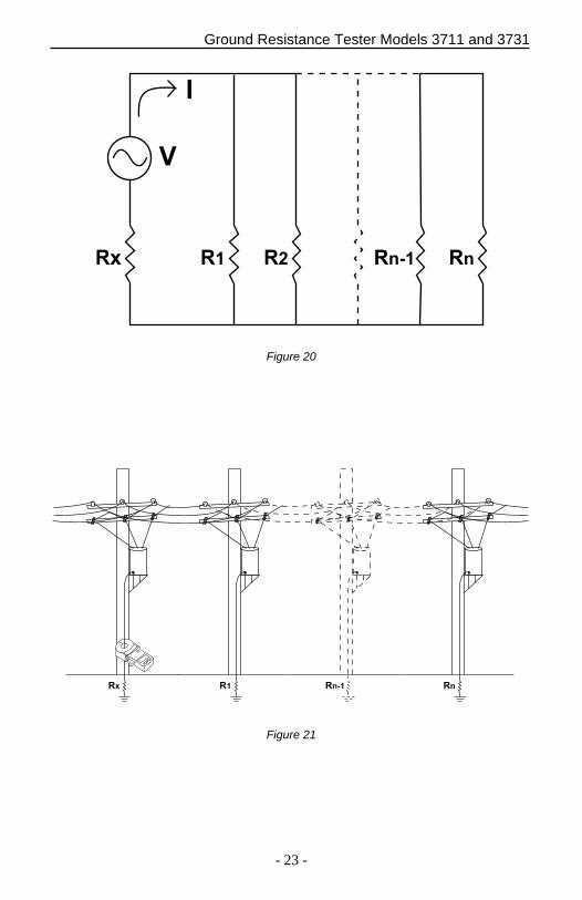
Typically grounded distribution system may be simulated by the basic circuit shown in Fig. 20 or an equivalent circuit, shown in Fig. 21. If voltage (V) is applied to any measured grounding electrode Rx through a special transformer, current (I) flows through the circuit, thereby establishing the following equation:
�
�� �� �
�
Σ
��
�
�
�� ��
Σ�
���
�
��
Therefore, V/I = Rx is established. If I is detected and measured with V kept constant, the measured grounding electrode resistance Rx can be obtained. A signal is fed to a special transformer via a power amplifier from a 2403Hz constant voltage oscillator. The resulting current is then sensed by a detection CT. An active filter is used to dampen earth current at commercial frequency and high-frequency noise.
Example: If we clamp around any grounding electrode in a multi-grounded system, the measured value of the electrode under test will be the resistance of that particular rod in series with the equivalent parallel resistance value that the rest of the multi-grounded system represents. If we had an electrical system that had 101 grounding electrodes and each had a resistance value of 25, and we were to clamp around any electrode in the system, the measured value would be 25 in series with the equivalent parallel resistance or 0.25. The displayed value would be 25.2 (instrument resolution to 0.1).
V/I = 25 + 0.25
Rx = 25.2
In most field applications, the number of electrodes that make up a multi-grounded system would be higher, therefore the equivalent parallel resistance is negligible with respect to the rod under test.
where, usually
Ground Resistance Tester Models 3711 and 3731
- 23 -
�
�
�� �� �� ���� ��
Figure 20
�� �� ������
Figure 21
Ground Resistance Tester Models 3711 and 3731
- 24 -
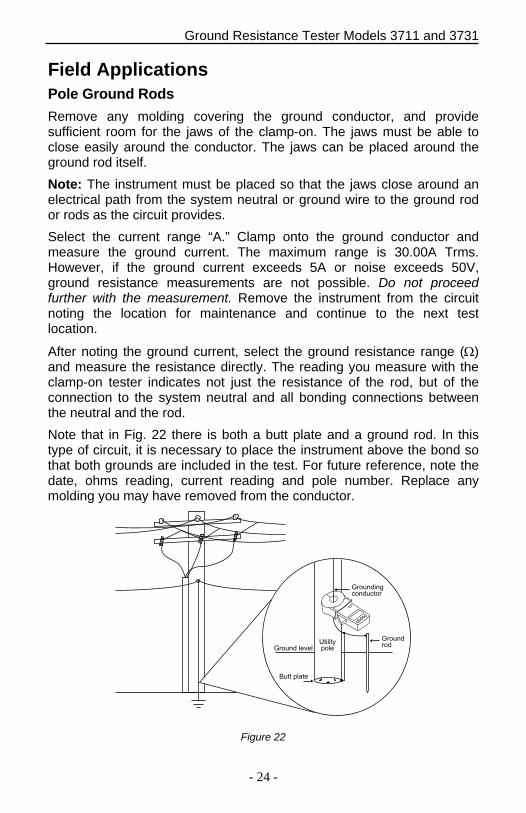
Field Applications Pole Ground Rods
Remove any molding covering the ground conductor, and provide sufficient room for the jaws of the clamp-on. The jaws must be able to close easily around the conductor. The jaws can be placed around the ground rod itself.
Note: The instrument must be placed so that the jaws close around an electrical path from the system neutral or ground wire to the ground rod or rods as the circuit provides.
Select the current range “A.” Clamp onto the ground conductor and measure the ground current. The maximum range is 30.00A Trms. However, if the ground current exceeds 5A or noise exceeds 50V, ground resistance measurements are not possible. Do not proceed further with the measurement. Remove the instrument from the circuit noting the location for maintenance and continue to the next test location.
After noting the ground current, select the ground resistance range () and measure the resistance directly. The reading you measure with the clamp-on tester indicates not just the resistance of the rod, but of the connection to the system neutral and all bonding connections between the neutral and the rod.
Note that in Fig. 22 there is both a butt plate and a ground rod. In this type of circuit, it is necessary to place the instrument above the bond so that both grounds are included in the test. For future reference, note the date, ohms reading, current reading and pole number. Replace any molding you may have removed from the conductor.
���������������
������ � � �
���������
�� ���
��������
Figure 22
Ground Resistance Tester Models 3711 and 3731
- 25 -
Note: A high reading or OL indicates one or more of the following:
A. Poor ground rod
B. Open ground conductor
C. High resistance bonds on the rod or splices on the conductor; watch for buried split butts, clamps, and hammer-on connections.
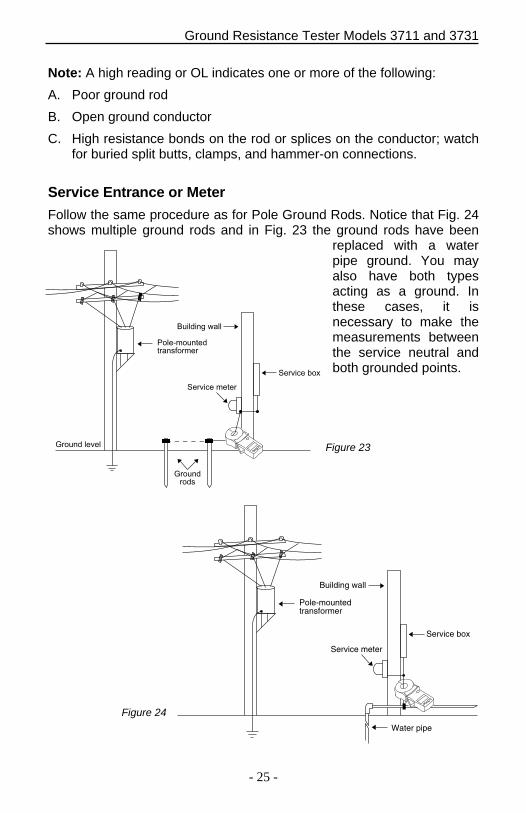
Service Entrance or Meter
Follow the same procedure as for Pole Ground Rods. Notice that Fig. 24 shows multiple ground rods and in Fig. 23 the ground rods have been
replaced with a water pipe ground. You may also have both types acting as a ground. In these cases, it is necessary to make the measurements between the service neutral and both grounded points. ������� �
������� �����
�������������������
�������� ����
��������
����� �����
Water pipe
Service box
Service meter
Pole-mountedtransformer
Building wall
Figure 23
Figure 24
Ground Resistance Tester Models 3711 and 3731
- 26 -
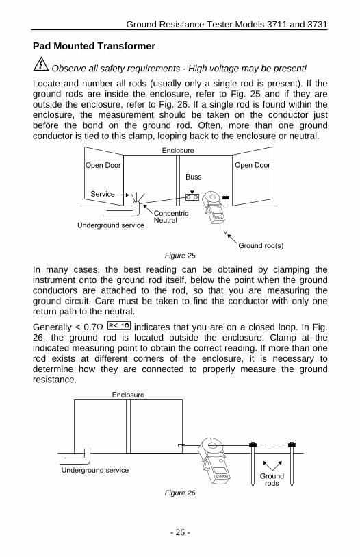
Pad Mounted Transformer
Observe all safety requirements - High voltage may be present!
Locate and number all rods (usually only a single rod is present). If the ground rods are inside the enclosure, refer to Fig. 25 and if they are outside the enclosure, refer to Fig. 26. If a single rod is found within the enclosure, the measurement should be taken on the conductor just before the bond on the ground rod. Often, more than one ground conductor is tied to this clamp, looping back to the enclosure or neutral.
������ ����
��� ����
����������� ������
����������������
�������
��
���� �������� ����
Figure 25
In many cases, the best reading can be obtained by clamping the instrument onto the ground rod itself, below the point when the ground conductors are attached to the rod, so that you are measuring the ground circuit. Care must be taken to find the conductor with only one return path to the neutral.
Generally < 0.7 � �� indicates that you are on a closed loop. In Fig. 26, the ground rod is located outside the enclosure. Clamp at the indicated measuring point to obtain the correct reading. If more than one rod exists at different corners of the enclosure, it is necessary to determine how they are connected to properly measure the ground resistance.
����������
�������
����� ����� ������
Figure 26
Ground Resistance Tester Models 3711 and 3731
- 27 -
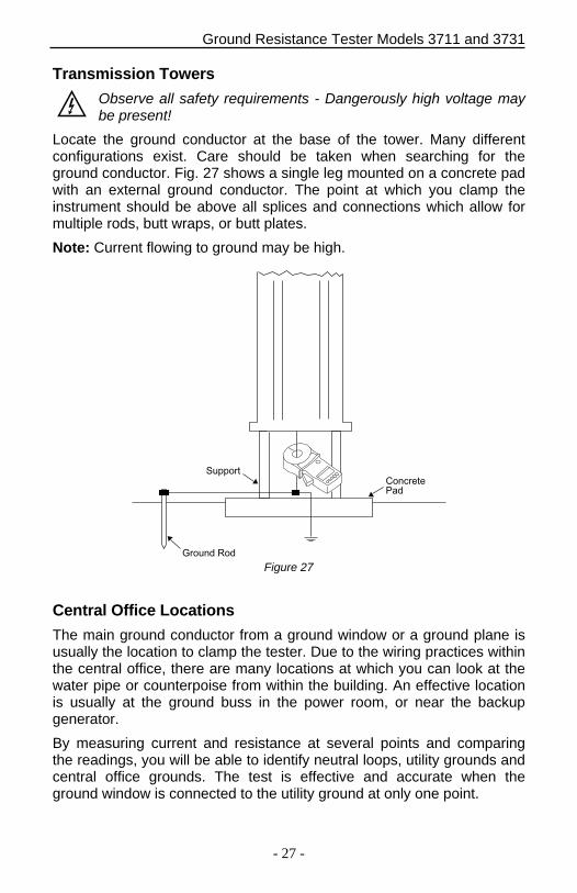
Transmission Towers
Observe all safety requirements - Dangerously high voltage may be present!
Locate the ground conductor at the base of the tower. Many different configurations exist. Care should be taken when searching for the ground conductor. Fig. 27 shows a single leg mounted on a concrete pad with an external ground conductor. The point at which you clamp the instrument should be above all splices and connections which allow for multiple rods, butt wraps, or butt plates.
Note: Current flowing to ground may be high.
������ ���
������� �������
Figure 27
Central Office Locations
The main ground conductor from a ground window or a ground plane is usually the location to clamp the tester. Due to the wiring practices within the central office, there are many locations at which you can look at the water pipe or counterpoise from within the building. An effective location is usually at the ground buss in the power room, or near the backup generator.
By measuring current and resistance at several points and comparing the readings, you will be able to identify neutral loops, utility grounds and central office grounds. The test is effective and accurate when the ground window is connected to the utility ground at only one point.
Ground Resistance Tester Models 3711 and 3731
- 28 -
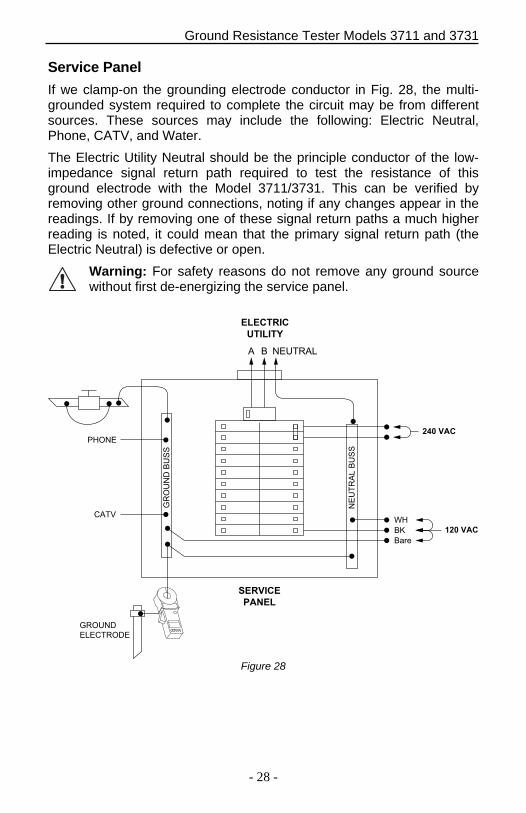
Service Panel
If we clamp-on the grounding electrode conductor in Fig. 28, the multi-grounded system required to complete the circuit may be from different sources. These sources may include the following: Electric Neutral, Phone, CATV, and Water.
The Electric Utility Neutral should be the principle conductor of the low-impedance signal return path required to test the resistance of this ground electrode with the Model 3711/3731. This can be verified by removing other ground connections, noting if any changes appear in the readings. If by removing one of these signal return paths a much higher reading is noted, it could mean that the primary signal return path (the Electric Neutral) is defective or open.
Warning: For safety reasons do not remove any ground source without first de-energizing the service panel.
��������
����� ��
�������
���
����
����
������
�����
� � �����
�������
�����
��� ���
����
��
�� ��� ���
Figure 28
Ground Resistance Tester Models 3711 and 3731
- 29 -
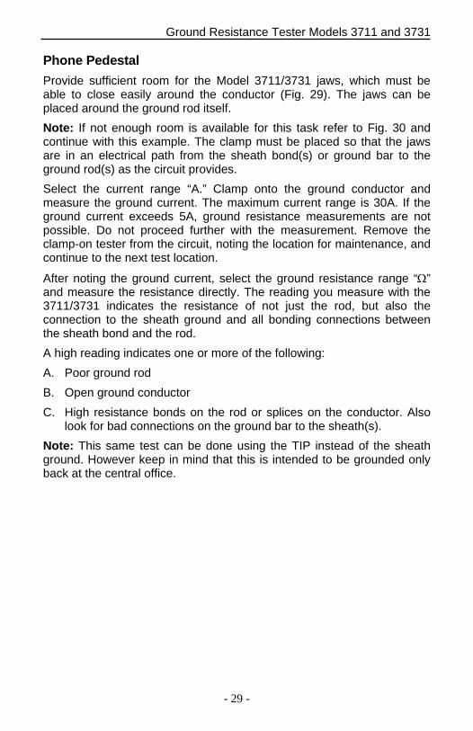
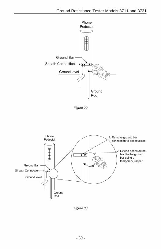
Phone Pedestal
Provide sufficient room for the Model 3711/3731 jaws, which must be able to close easily around the conductor (Fig. 29). The jaws can be placed around the ground rod itself.
Note: If not enough room is available for this task refer to Fig. 30 and continue with this example. The clamp must be placed so that the jaws are in an electrical path from the sheath bond(s) or ground bar to the ground rod(s) as the circuit provides.
Select the current range “A.” Clamp onto the ground conductor and measure the ground current. The maximum current range is 30A. If the ground current exceeds 5A, ground resistance measurements are not possible. Do not proceed further with the measurement. Remove the clamp-on tester from the circuit, noting the location for maintenance, and continue to the next test location.
After noting the ground current, select the ground resistance range “” and measure the resistance directly. The reading you measure with the 3711/3731 indicates the resistance of not just the rod, but also the connection to the sheath ground and all bonding connections between the sheath bond and the rod.
A high reading indicates one or more of the following:
A. Poor ground rod
B. Open ground conductor
C. High resistance bonds on the rod or splices on the conductor. Also look for bad connections on the ground bar to the sheath(s).
Note: This same test can be done using the TIP instead of the sheath ground. However keep in mind that this is intended to be grounded only back at the central office.
Ground Resistance Tester Models 3711 and 3731
- 30 -
������ ��
�� �� ���������
������
���
����
���� �
������ � �
Figure 29
������ ��
�� �� ���������
������
���
����
���� �
������ � �
�� ��� ������ � �
��������� �� ���� � ���
�� ����� ���� � ���
� � �� �� ������
� � �����
����� �� ����
Figure 30
Ground Resistance Tester Models 3711 and 3731
- 31 -
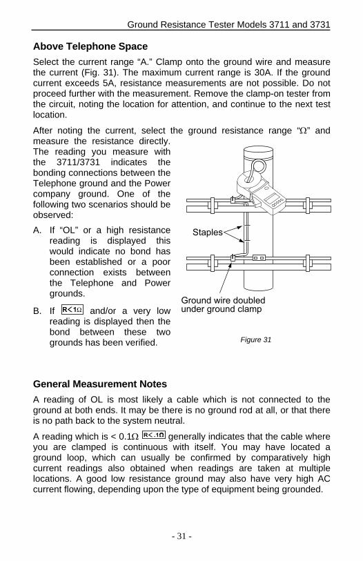
Above Telephone Space
Select the current range “A.” Clamp onto the ground wire and measure the current (Fig. 31). The maximum current range is 30A. If the ground current exceeds 5A, resistance measurements are not possible. Do not proceed further with the measurement. Remove the clamp-on tester from the circuit, noting the location for attention, and continue to the next test location.
After noting the current, select the ground resistance range “” and measure the resistance directly. The reading you measure with the 3711/3731 indicates the bonding connections between the Telephone ground and the Power company ground. One of the following two scenarios should be observed:
A. If “OL” or a high resistance reading is displayed this would indicate no bond has been established or a poor connection exists between the Telephone and Power grounds.
B. If � � and/or a very low reading is displayed then the bond between these two grounds has been verified.
General Measurement Notes
A reading of OL is most likely a cable which is not connected to the ground at both ends. It may be there is no ground rod at all, or that there is no path back to the system neutral.
A reading which is < 0.1 � �� generally indicates that the cable where you are clamped is continuous with itself. You may have located a ground loop, which can usually be confirmed by comparatively high current readings also obtained when readings are taken at multiple locations. A good low resistance ground may also have very high AC current flowing, depending upon the type of equipment being grounded.
Figure 31
�������
��� ��� ���� �� � ��� �����
Ground Resistance Tester Models 3711 and 3731
- 32 -
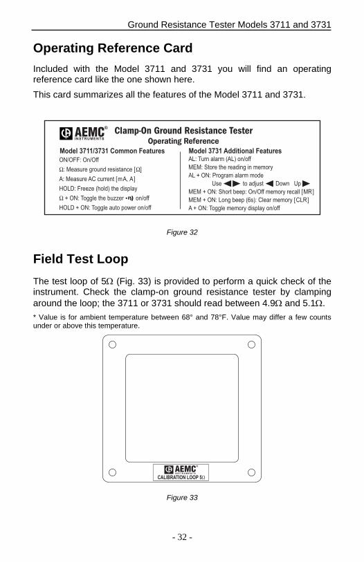
Operating Reference Card
Included with the Model 3711 and 3731 you will find an operating reference card like the one shown here.
This card summarizes all the features of the Model 3711 and 3731.
����� ����� ����� �������� ����� ��� ������� �� ��������
������� ������
� �� � ��� �� �������� ��
�� �� � �� � ���� ���� ��
����� ��� � �!�" � ���#!�$
٠% ��� &���! � ' ��� ������
���� % ��� &���! � �� #�(� ������
��� & �� �!��� ���" ������
)� *��� � ������ �� ����$
�� % ��� +������ �!��� ���
, -� �� ��. �� ��(� -#
) % ��� * ��� '#� ������ ����$ ���!! �/�
) % ��� ���� '# �0�"� �!�� ����$ ���/�
� % ��� &���! ����$ ���#!�$ ������
�������� �� �� ���������� �������������� ������� �
�
�����������
Figure 32
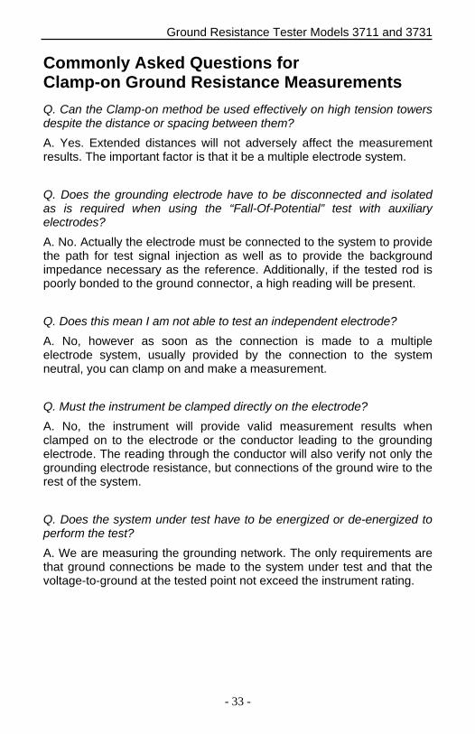
Field Test Loop
The test loop of 5 (Fig. 33) is provided to perform a quick check of the instrument. Check the clamp-on ground resistance tester by clamping around the loop; the 3711 or 3731 should read between 4.9 and 5.1.
* Value is for ambient temperature between 68° and 78°F. Value may differ a few countsunder or above this temperature.
®
I N S T R U M E N T S
CALIBRATION LOOP 5Ω
Figure 33
Ground Resistance Tester Models 3711 and 3731
- 33 -
Commonly Asked Questions for Clamp-on Ground Resistance Measurements
Q. Can the Clamp-on method be used effectively on high tension towers despite the distance or spacing between them?
A. Yes. Extended distances will not adversely affect the measurement results. The important factor is that it be a multiple electrode system.
Q. Does the grounding electrode have to be disconnected and isolated as is required when using the “Fall-Of-Potential” test with auxiliary electrodes?
A. No. Actually the electrode must be connected to the system to provide the path for test signal injection as well as to provide the background impedance necessary as the reference. Additionally, if the tested rod is poorly bonded to the ground connector, a high reading will be present.
Q. Does this mean I am not able to test an independent electrode?
A. No, however as soon as the connection is made to a multiple electrode system, usually provided by the connection to the system neutral, you can clamp on and make a measurement.
Q. Must the instrument be clamped directly on the electrode?
A. No, the instrument will provide valid measurement results when clamped on to the electrode or the conductor leading to the grounding electrode. The reading through the conductor will also verify not only the grounding electrode resistance, but connections of the ground wire to the rest of the system.
Q. Does the system under test have to be energized or de-energized to perform the test?
A. We are measuring the grounding network. The only requirements are that ground connections be made to the system under test and that the voltage-to-ground at the tested point not exceed the instrument rating.
Ground Resistance Tester Models 3711 and 3731
- 34 -
Q. Can the clamp-on method be used for substation grid resistance testing?
A. It depends. It can be used as long as the instrument can be clamped onto a point on the grounding system at a common point where it ties to the system neutral. Testing a grid must be treated as if it were a single electrode. Often, clamping on to points within the grid system will yield a closed loop reading.
Q. How does clamp-on ground testing compare with the standard “Fall-Of-Potential” test?
A. Empirical testing has validated that when performed correctly, both methods will provide accurate and repeatable readings for ground electrode resistance.
Q. How large a conductor can the jaw accommodate?
A. The inner diameter of the jaw is 1.25" and can accommodate cables up to 1000 kcmil.
Maintenance
Warning To ensure optimum performance, it is important to keep the probe jaw
mating surfaces clean at all times. Failure to do so may result in error in readings. To clean the probe jaws, use a lint free clean cloth, or if the jaws are pitted use a very fine sand paper (fine 600 grit) to avoid scratching the jaw, then gently clean with a soft cloth. Do not leave any residue.
For maintenance use only specified factory replacement parts.
Avoid electrical shock: do not attempt to perform any servicing unlessyou are qualified to do so.
Avoid electrical shock and/or damage to the instrument: do not allowwater or other foreign substances into the case. Disconnect the unitfrom all circuits and test cables before opening the case. Use cautionwith metallic tools that may short battery packs, power supplies, etc.
Ground Resistance Tester Models 3711 and 3731
- 35 -
Battery Replacement Procedure The Clamp-On Ground Resistance Testers are powered by a single 9V battery. The battery replacement indicator will display continuously when battery replacement is required.
Recommended replacement type is Alkaline (IEC 6LF22, 6LR61 or NEDA 1604A). Ni-Cad batteries may also be used. To change the battery, refer to Figure 15, page 18 and follow this procedure.
1. The instrument must be OFF and disconnected from any conductor.
2. Place the meter face down and remove the two Phillips screws onthe back of the instrument.
3. Remove back cover by pulling it down and away from the instrument.
4. Lift the battery away from the case and disconnect the battery.
5. Connect the new battery and position the leads so that they won’t getpinched when the cover is replaced.
6. Replace the back cover noting that it slips beneath the hold down lipand fits securely into position.
7. Install and tighten screws.
Typical battery life is approximately 8 hours of use or about 1000 separate 30-second measurements.
Troubleshooting
Symptom Indication/Recommended Action
Instrument will not turn ON Low Battery Replacement required
Continuous audible tone Alarm setpoint tripped Deactivate Alarm or Change Setpoint Trigger mode
Display is erratic Foreign matter in jaws Clean jaw mating surfaces
Function controls inoperative Hold button on Turn HOLD off
Light pulsing audible beep Normal operation Battery power management feature
Ground Resistance Tester Models 3711 and 3731
- 36 -
Repair and Calibration To ensure that your instrument meets factory specifications, we recommend that it be submitted to our factory Service Center at one-year intervals for recalibration, or as required by other standards or internal procedures.
For instrument repair and calibration: You must contact our Service Center for a Customer Service Authorization number (CSA#). This will ensure that when your instrument arrives, it will be tracked and processed promptly. Please write the CSA# on the outside of the shipping container. If the instrument is returned for calibration, we need to know if you want a standard calibration, or a calibration traceable to N.I.S.T. (includes calibration certificate plus recorded calibration data).
Chauvin Arnoux®, Inc. d.b.a. AEMC® Instruments
15 Faraday Drive Dover, NH 03820 USA Tel: (800) 945-2362 (Ext. 360)
(603) 749-6434 (Ext. 360) Fax: (603) 742-2346 or (603) 749-6309
(Or contact your authorized distributor)
Costs for repair, standard calibration, and calibration traceable to N.I.S.T. are available.
NOTE: All customers must obtain a CSA# before returning any instrument.
Technical and Sales Assistance If you are experiencing any technical problems, or require any assistance with the proper operation or application of your instrument, please call, fax or e-mail our technical support hotline:
Chauvin Arnoux®, Inc. d.b.a. AEMC® Instruments
Tel. (800) 945-2362 (Ext. 351) (603) 749-6434 (Ext. 351) Fax: (603) 742-2346 [email protected]


Chauvin Arnoux®, Inc. d.b.a AEMC® Instruments 15 Faraday Drive • Dover, NH 03820 USA
www.aemc.com
99-MAN 100218 v15 02/18