Chapter - 1 Direct Current Circuitscremaldi/PHYS321/chapter-1.pdf · (5) Physical currents through...
25
1 • RESISTANCE • KIRKOFFS LAW and LOOP-MESH METHOD • VOLTAGE DIVIDER • INTERNAL RESISTANCE and OUTPUT IMPEDANCE • HOW TO MEASURE OUTPUT IMPEDANCE OF A DEVICE •THEVENIN's THEOREM Chapter - 1 Direct Current Circuits
Transcript of Chapter - 1 Direct Current Circuitscremaldi/PHYS321/chapter-1.pdf · (5) Physical currents through...
1
• RESISTANCE • KIRKOFFS LAW and LOOP-MESH METHOD
• VOLTAGE DIVIDER
• INTERNAL RESISTANCE and OUTPUT IMPEDANCE
• HOW TO MEASURE OUTPUT IMPEDANCE OF A DEVICE • THEVENIN's THEOREM
Chapter - 1 Direct Current Circuits
2
Resistivity !
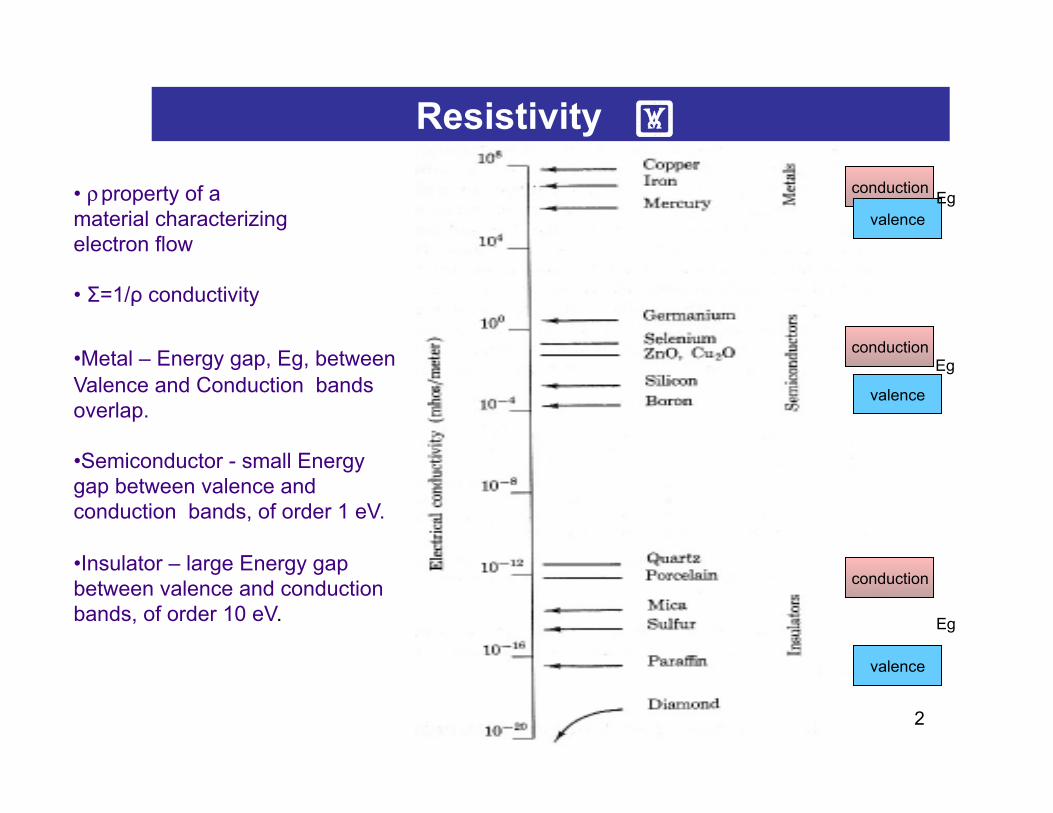
• ρ property of a material characterizing electron flow • Σ=1/ρ conductivity
• Metal – Energy gap, Eg, between Valence and Conduction bands overlap.
• Semiconductor - small Energy gap between valence and conduction bands, of order 1 eV.
• Insulator – large Energy gap between valence and conduction bands, of order 10 eV.
conduction
valence
conduction
valence
conduction
valence
Eg
Eg
Eg
3
Resistance
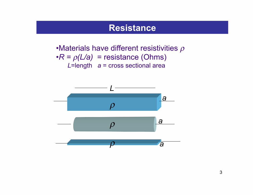
• Materials have different resistivities ρ • R = ρ(L/a) = resistance (Ohms)
L=length a = cross sectional area
L a
ρ
a ρ
ρ a

4
5
Ohm's Law
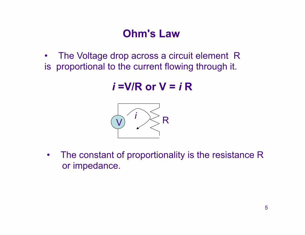
• The Voltage drop across a circuit element R is proportional to the current flowing through it.
R i V
i =V/R or V = i R
• The constant of proportionality is the resistance R or impedance.
6
Series and Parallel Connections
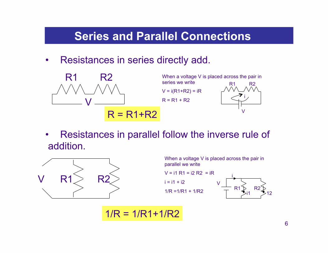
• Resistances in series directly add.
• Resistances in parallel follow the inverse rule of addition.
R1 R2
R = R1+R2
When a voltage V is placed across the pair in series we write
V = i(R1+R2) = iR
R = R1 + R2
When a voltage V is placed across the pair in parallel we write
V = i1 R1 = i2 R2 = iR
i = i1 + i2
1/R =1/R1 + 1/R2
R1 R2
V i
R1 12
V R2
i1
i R1 R2
1/R = 1/R1+1/R2
V
V
7
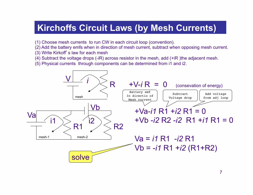
Kirchoffs Circuit Laws (by Mesh Currents)
+V-i R = 0 (consevation of energy) V
R i
(1) Choose mesh currents to run CW in each circuit loop (convention). (2) Add the battery emfs when in direction of mesh current, subtract when opposing mesh current. (3) Write Kirkoff’s law for each mesh (4) Subtract the voltage drops (-iR) across resistor in the mesh, add (+iR )the adjacent mesh. (5) Physical currents through components can be determined from i1 and i2.
+Va-i1 R1 +i2 R1 = 0 +Vb -i2 R2 -i2 R1 +i1 R1 = 0 Va = i1 R1 -i2 R1 Vb = -i1 R1 +i2 (R1+R2)
solve
Va R1
i1 R2
i2
Vb mesh
mesh-1 mesh-2
Subtract !Voltage drop
Add voltage !from adj loop
Battery emf!In directio of!Mesh current

8
Example
5V 10Ω
i1 2Ω
i2
5V - 10 i1 + 10 i2 = 0 0 - 2 i2 - 10 i2 + 10 i1 = 0 1) 5V = 10 i1 - 10 i2 2) 0 = -10 i1 + 12 i2 5V = 0 + 2 i2 adding 1) + 2) --> i2 = 5/2 A
i1= (12/10)i2 = 3A i2 = 5/2 A I = i1 = 3A
Find I1, I2, I ? I
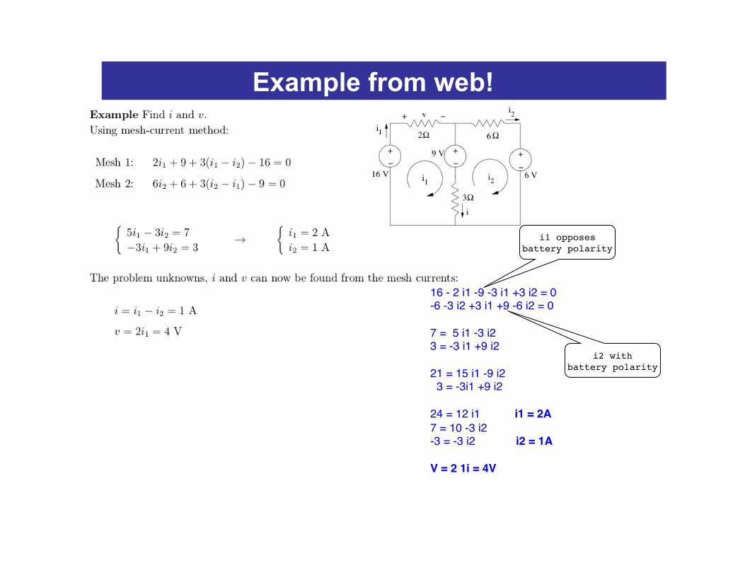
16 - 2 i1 -9 -3 i1 +3 i2 = 0"-6 -3 i2 +3 i1 +9 -6 i2 = 0""7 = 5 i1 -3 i2"3 = -3 i1 +9 i2""21 = 15 i1 -9 i2" 3 = -3i1 +9 i2""24 = 12 i1 i1 = 2A"7 = 10 -3 i2"-3 = -3 i2 i2 = 1A!!V = 2 1i = 4V "
i1 opposes !battery polarity
i2 with !battery polarity
Example from web!
10
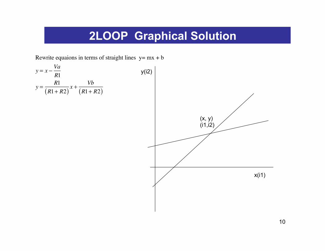
2LOOP Graphical Solution Rewrite equaions in terms of straight lines y= mx + b
y = x −VaR1
y =R1
R1+ R2( ) x +Vb
R1+ R2( )
x(i1)
y(i2)
(x, y) (i1,i2)
11
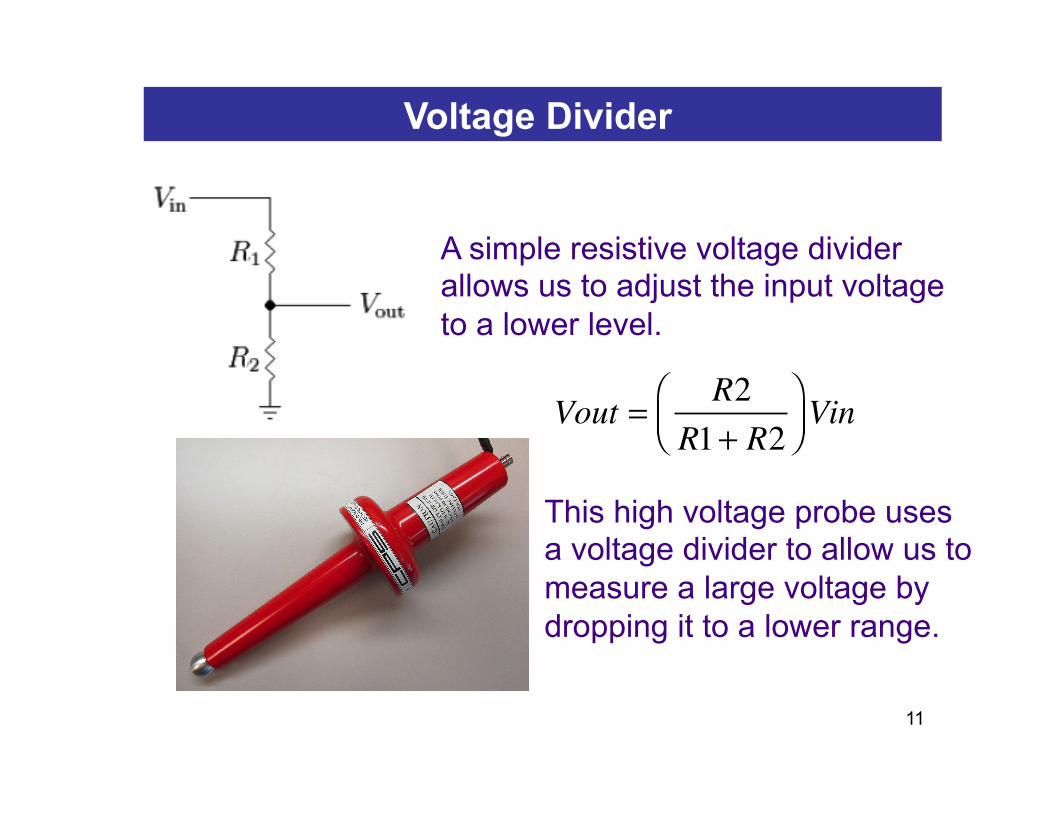
Voltage Divider
A simple resistive voltage divider allows us to adjust the input voltage to a lower level.
This high voltage probe uses a voltage divider to allow us to measure a large voltage by dropping it to a lower range.
Vout =R2
R1+ R2⎛⎝⎜
⎞⎠⎟Vin
12
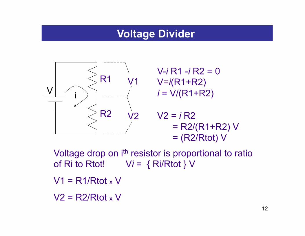
Voltage Divider
V2
V R1
i
R2
V-i R1 -i R2 = 0 V=i(R1+R2) i = V/(R1+R2) V2 = i R2 = R2/(R1+R2) V = (R2/Rtot) V
Voltage drop on ith resistor is proportional to ratio of Ri to Rtot! Vi = { Ri/Rtot } V
V1 = R1/Rtot x V
V2 = R2/Rtot x V
V1
13
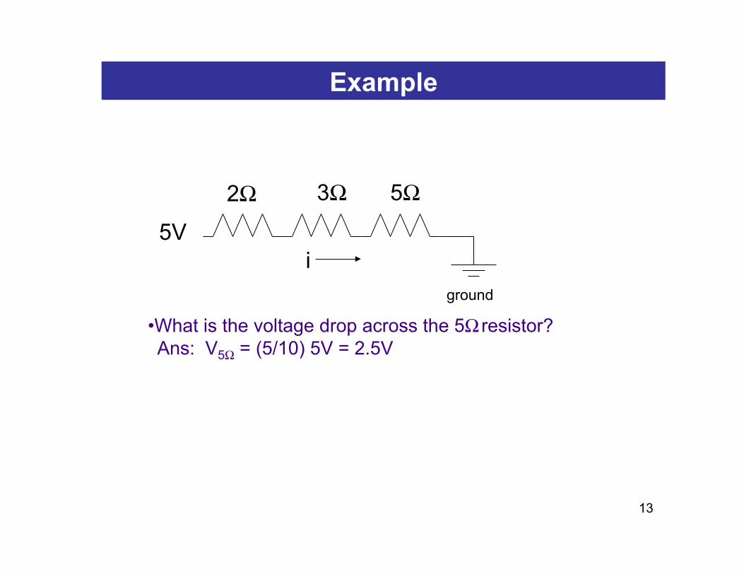
Example
ground i
2Ω
5V
5Ω 3Ω
• What is the voltage drop across the 5Ω resistor? Ans: V5Ω = (5/10) 5V = 2.5V
14
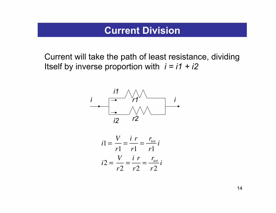
Current Division
Current will take the path of least resistance, dividing Itself by inverse proportion with i = i1 + i2
i1 = Vr1
=i rr1
= rtotr1
i
i2 = Vr2
=i rr2
= rtotr2
i
i i1
i2
r1
r2
i
15
Power Dissipated by a Circuit Element
V
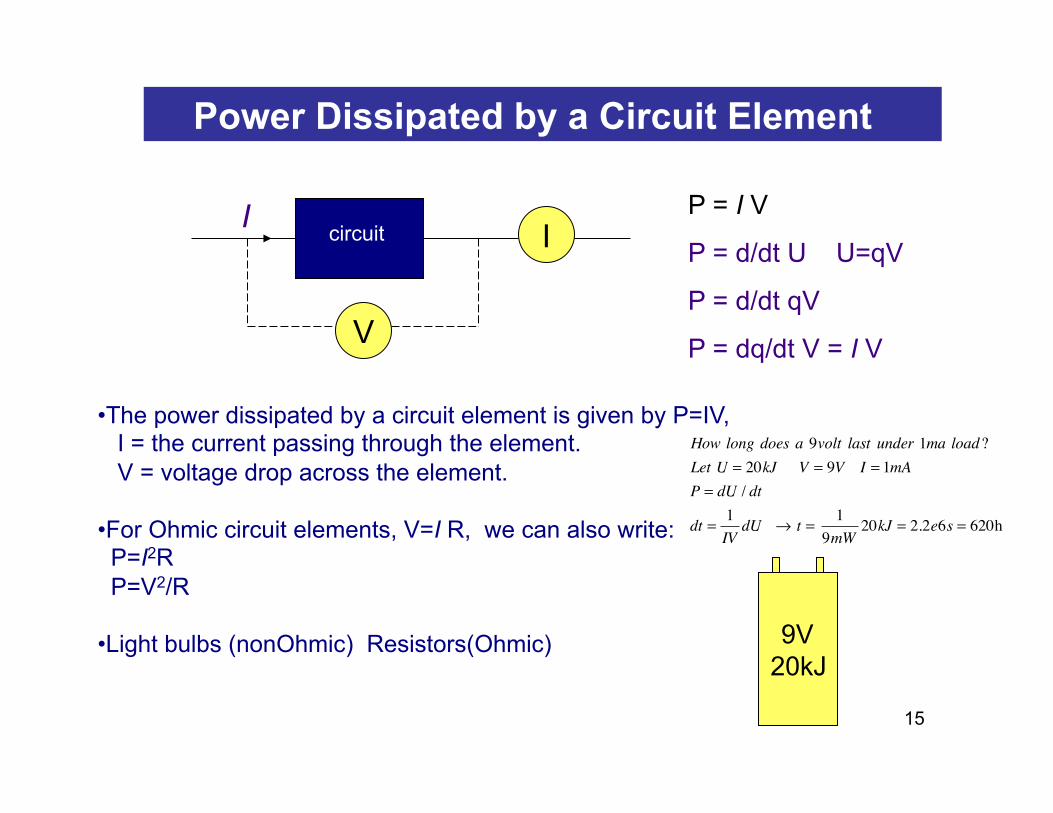
I I P = I V
P = d/dt U U=qV
P = d/dt qV
P = dq/dt V = I V
• The power dissipated by a circuit element is given by P=IV, I = the current passing through the element. V = voltage drop across the element. • For Ohmic circuit elements, V=I R, we can also write: P=I2R P=V2/R • Light bulbs (nonOhmic) Resistors(Ohmic) 9V
20kJ
How long does a 9volt last under 1ma load?Let U = 20kJ V = 9V I = 1mAP = dU / dt
dt =1IV
dU → t = 19mW
20kJ = 2.2e6s = 620h
circuit
16
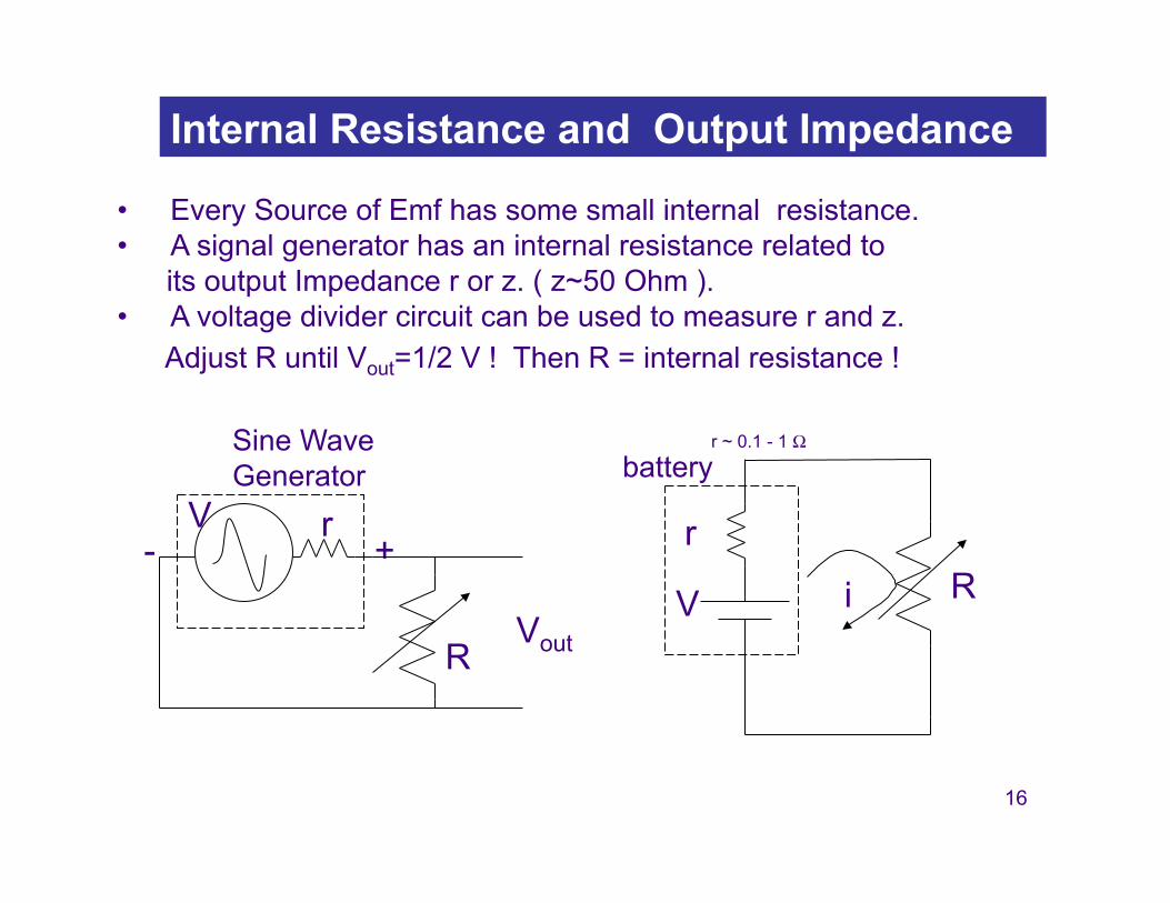
Internal Resistance and Output Impedance
• Every Source of Emf has some small internal resistance. • A signal generator has an internal resistance related to its output Impedance r or z. ( z~50 Ohm ). • A voltage divider circuit can be used to measure r and z. Adjust R until Vout=1/2 V ! Then R = internal resistance !
battery
V i R r
r ~ 0.1 - 1 Ω Sine Wave Generator
r + -
R Vout
V
17
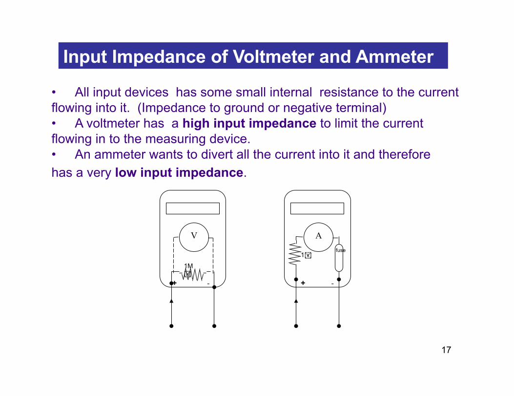
Input Impedance of Voltmeter and Ammeter
• All input devices has some small internal resistance to the current flowing into it. (Impedance to ground or negative terminal) • A voltmeter has a high input impedance to limit the current flowing in to the measuring device. • An ammeter wants to divert all the current into it and therefore has a very low input impedance.
+ - 1M!
V
+ -
1!
A
fuse
18
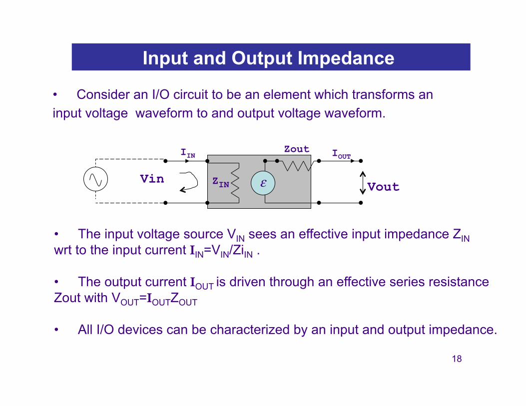
Input and Output Impedance
• Consider an I/O circuit to be an element which transforms an input voltage waveform to and output voltage waveform.
• The input voltage source VIN sees an effective input impedance ZIN wrt to the input current IIN=VIN/ZiIN .
• The output current IOUT is driven through an effective series resistance Zout with VOUT=IOUTZOUT
• All I/O devices can be characterized by an input and output impedance.
Vout Vin ZIN ε
Zout IIN IOUT
19
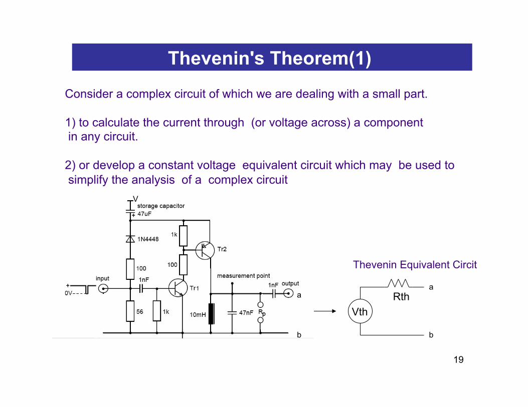
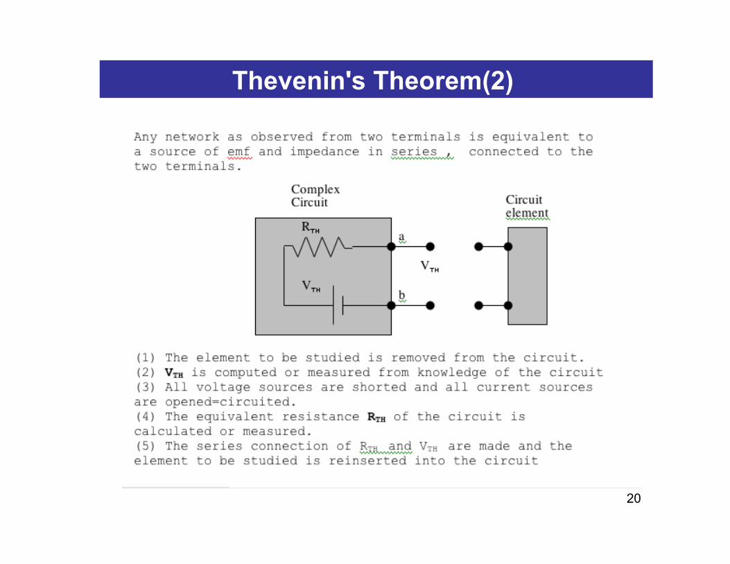
Consider a complex circuit of which we are dealing with a small part. 1) to calculate the current through (or voltage across) a component in any circuit. 2) or develop a constant voltage equivalent circuit which may be used to simplify the analysis of a complex circuit
Thevenin's Theorem(1)
Vth Rth a
b
a
b
Thevenin Equivalent Circit
V
20
Thevenin's Theorem(2)
21
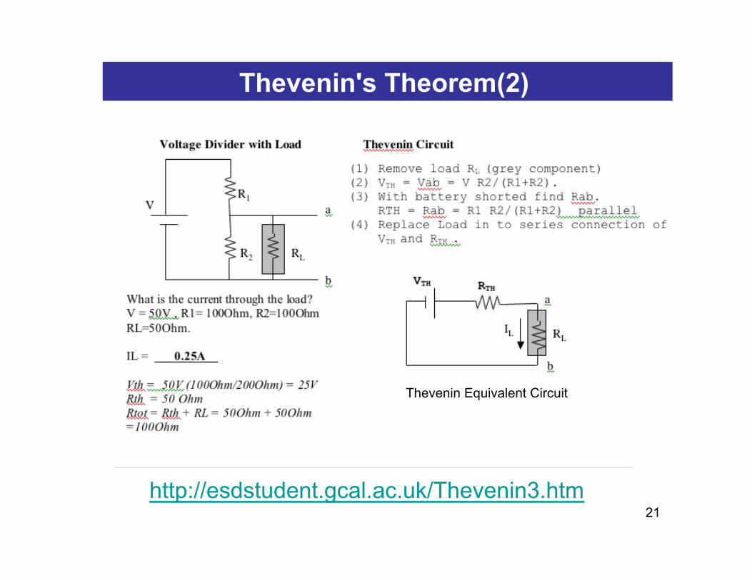
Thevenin's Theorem(2)
Thevenin Equivalent Circuit
http://esdstudent.gcal.ac.uk/Thevenin3.htm
22
2 Port Network (extra)
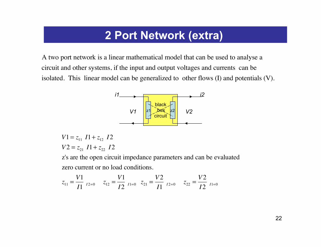
V1 = z11 I1+ z12 I2V2 = z21 I1+ z22 I2z's are the open circuit impedance parameters and can be evaluated zero current or no load conditions.
z11 =V1I1 I 2=0 z12 =
V1I2 I1=0 z21 =
V2I1 I 2=0 z22 =
V2I2 I1=0
black box
circuit
i1 i2
V1 V2
A two port network is a linear mathematical model that can be used to analyse a circuit and other systems, if the input and output voltages and currents can be isolated. This linear model can be generalized to other flows (I) and potentials (V).
z1 z2
23
2 Port Network (extra)
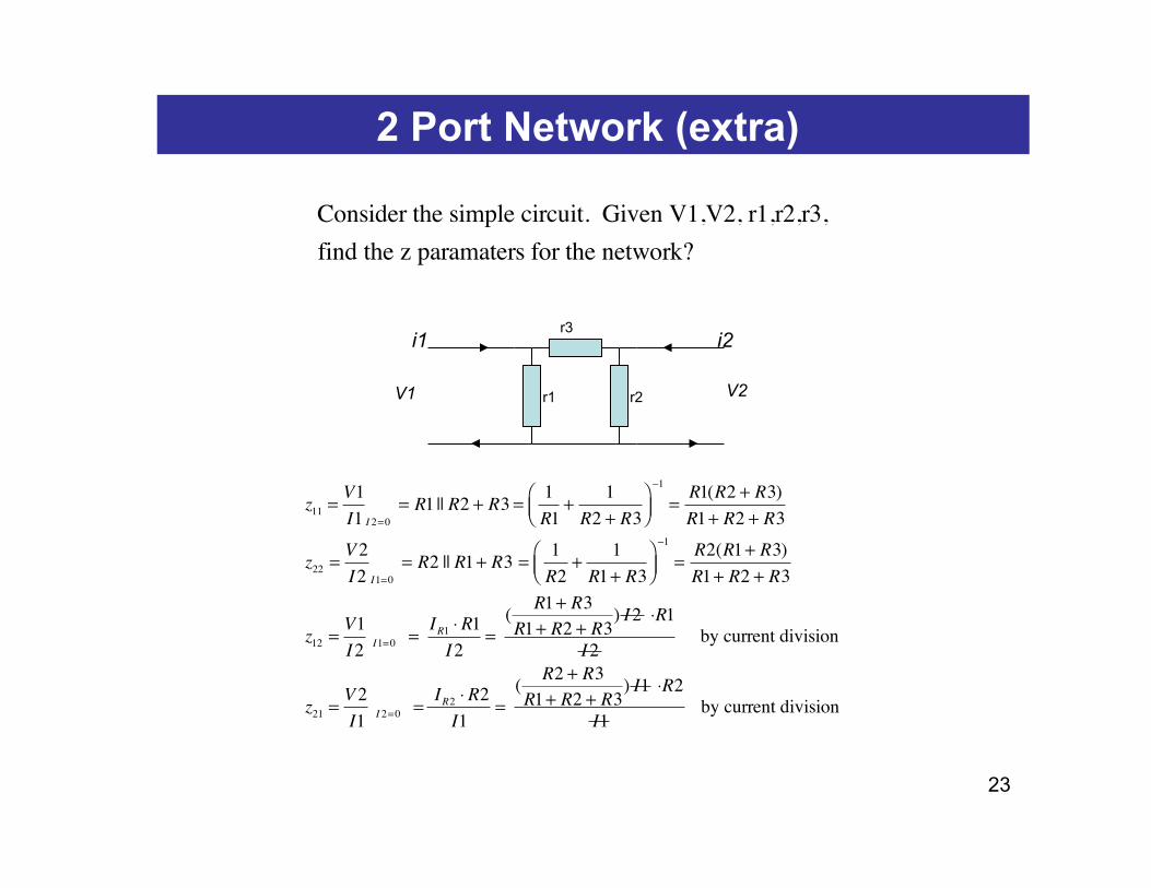
z11 =V1I1 I 2=0
= R1 || R2 + R3 = 1R1
+1
R2 + R3⎛⎝⎜
⎞⎠⎟−1
=R1(R2 + R3)R1+ R2 + R3
z22 =V2I2 I1=0
= R2 || R1+ R3 = 1R2
+1
R1+ R3⎛⎝⎜
⎞⎠⎟−1
=R2(R1+ R3)R1+ R2 + R3
z12 =V1I2 I1=0 =
IR1 ⋅ R1I2
= ( R1+ R3R1+ R2 + R3
) I2 ⋅R1
I2 by current division
z21 =V2I1 I 2=0 =
IR2 ⋅ R2I1
= ( R2 + R3R1+ R2 + R3
) I1 ⋅R2
I1 by current division
i1 i2
V1 V2
Consider the simple circuit. Given V1,V2, r1,r2,r3, find the z paramaters for the network?
r1 r2
r3
24
2 Port Network (example)
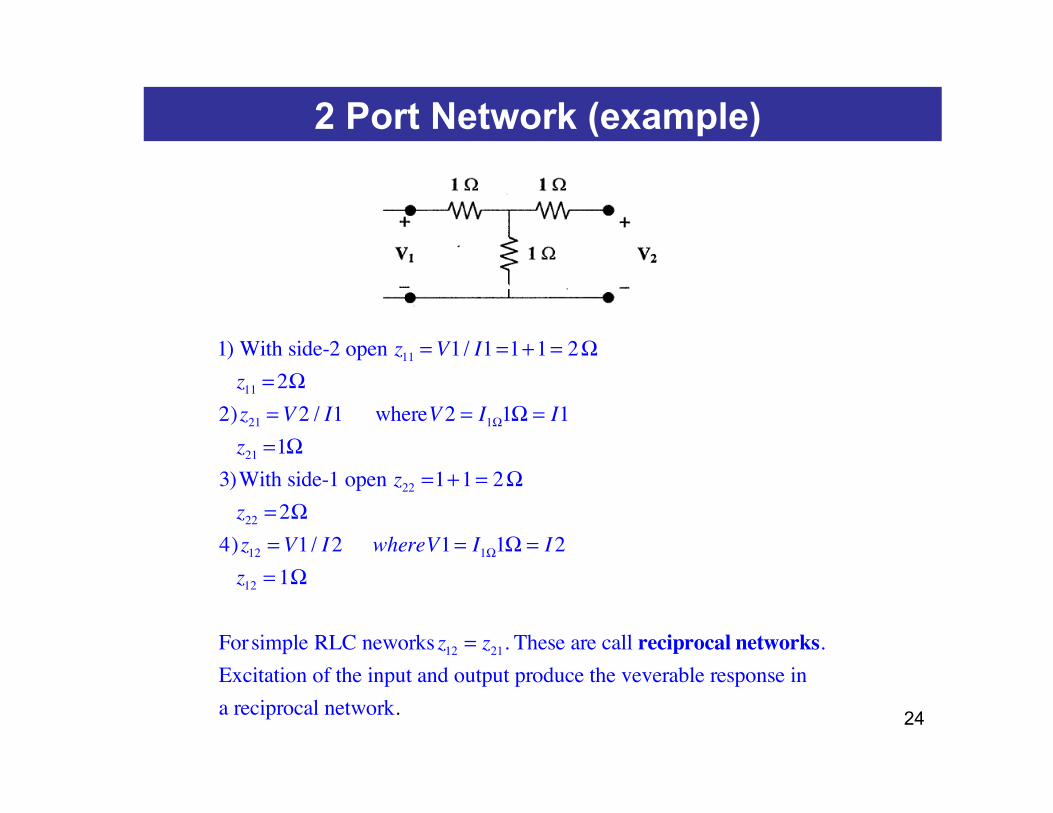
1) With side-2 open z11 =V1/ I1=1+1= 2Ωz11 =2Ω
2)z21 =V2 / I1 whereV2 = I1Ω1Ω = I1z21 =1Ω
3)With side-1 open z22 =1+1= 2Ωz22 =2Ω
4)z12 =V1/ I2 whereV1= I1Ω1Ω = I2z12 = 1Ω
Forsimple RLC neworks z12 = z21. These are call reciprocal networks.Excitation of the input and output produce the veverable response in a reciprocal network.
25
2 Port Network (example)
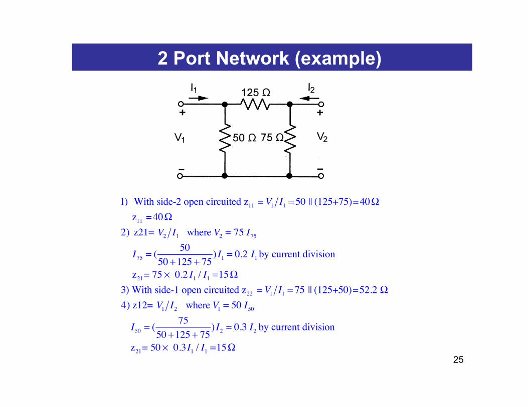
1) With side-2 open circuited z11 = V1 I1 =50 || (125+75)=40Ωz11 =40Ω
2) z21= V2 I1 where V2 = 75 I75
I75 = ( 5050 +125 + 75
) I1 = 0.2 I1 by current division
z21= 75 × 0.2 I1 / I1 =15Ω3) With side-1 open circuited z22 = V1 I1 = 75 || (125+50)=52.2 Ω4) z12= V1 I2 where V1 = 50 I50
I50 = ( 7550 +125 + 75
) I2 = 0.3 I2 by current division
z21= 50 × 0.3I1 / I1 =15Ω
![[PPT]Kirchoff’s Laws - NAU jan.ucc.nau.edu web serversh295/EE188/slides/KirchoffLaws.ppt · Web viewKirchoff’s Laws Chapter 3 Example Circuit Writing KVL, I1∙14.4Ω – 50 v](https://static.fdocument.org/doc/165x107/5ab07e597f8b9ac66c8b4db2/pptkirchoffs-laws-nau-januccnauedu-web-sh295ee188slideskirchofflawspptweb.jpg)


![The substituent effect of π-electron delocalization in N … · 2020-04-30 · R[F2 >2σ(F2)] Final R indices R1=0.0572,wR2=0.0958 R1=0.0364,wR2=0.0549 R1=0.0252, wR2=0.0721 R indices](https://static.fdocument.org/doc/165x107/5f6e463324a3df634645499f/the-substituent-effect-of-electron-delocalization-in-n-2020-04-30-rf2-2ff2.jpg)


![Image Processing using Graphs - Instituto de Computaçãoafalcao/talks/lecture1-ascsp.pdf · Image Processing using Graphs ... [2, 3, 4] in the ... I2 New features may result from](https://static.fdocument.org/doc/165x107/5ac740377f8b9acb7c8bbbdf/image-processing-using-graphs-instituto-de-afalcaotalkslecture1-ascsppdfimage.jpg)