CE 115 Intro to Civil Eng: Geotechnical Engineering Soil Pressure Acting … 115 Geotech...
7
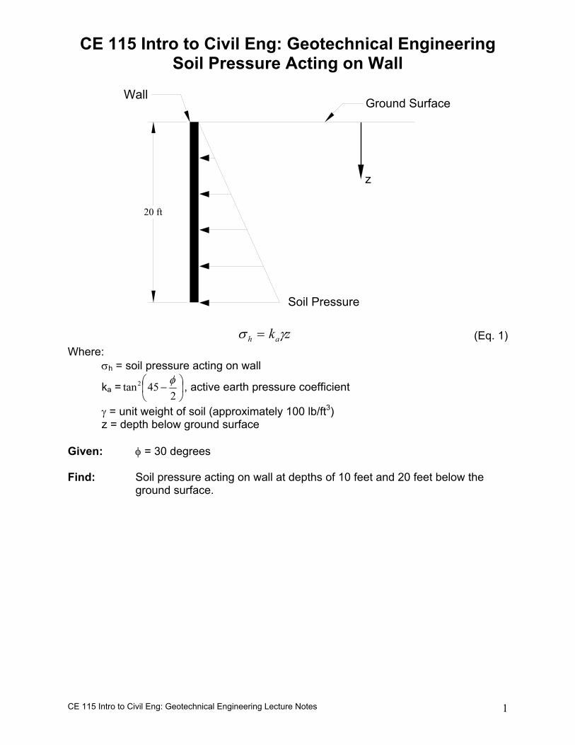
CE 115 Intro to Civil Eng: Geotechnical Engineering Lecture Notes 1 CE 115 Intro to Civil Eng: Geotechnical Engineering Soil Pressure Acting on Wall Ground Surface Soil Pressure 20 ft z Wall z k a h γ σ = (Eq. 1) Where: σ h = soil pressure acting on wall k a = − 2 45 tan 2 φ , active earth pressure coefficient γ = unit weight of soil (approximately 100 lb/ft 3 ) z = depth below ground surface Given: φ = 30 degrees Find: Soil pressure acting on wall at depths of 10 feet and 20 feet below the ground surface.
Transcript of CE 115 Intro to Civil Eng: Geotechnical Engineering Soil Pressure Acting … 115 Geotech...
CE 115 Intro to Civil Eng: Geotechnical Engineering Lecture Notes 1
CE 115 Intro to Civil Eng: Geotechnical Engineering Soil Pressure Acting on Wall
Ground Surface
Soil Pressure
20 ft
z
Wall
zkah γσ = (Eq. 1) Where: σh = soil pressure acting on wall
ka =
−
245tan2 φ , active earth pressure coefficient
γ = unit weight of soil (approximately 100 lb/ft3) z = depth below ground surface Given: φ = 30 degrees Find: Soil pressure acting on wall at depths of 10 feet and 20 feet below the
ground surface.
CE 115 Intro to Civil Eng: Geotechnical Engineering Lecture Notes 2
20 ft
z
Wall
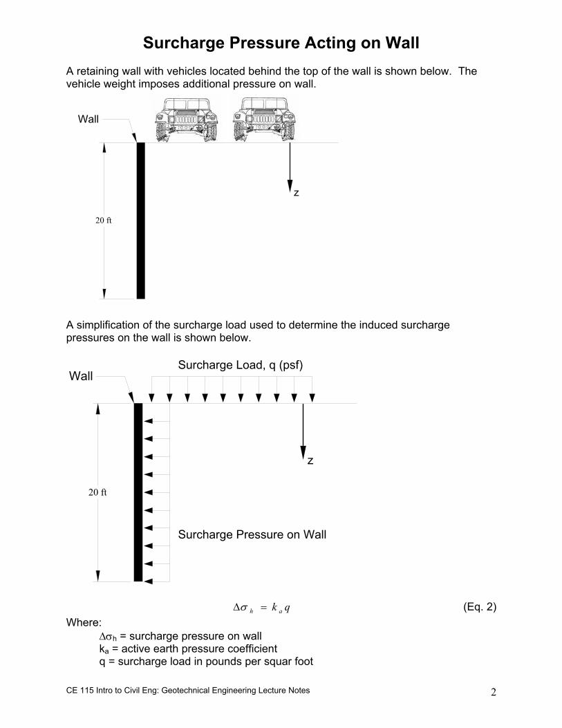
Surcharge Pressure Acting on Wall A retaining wall with vehicles located behind the top of the wall is shown below. The vehicle weight imposes additional pressure on wall.
A simplification of the surcharge load used to determine the induced surcharge pressures on the wall is shown below.
20 ft
z
Wall
Surcharge Pressure on Wall
Surcharge Load, q (psf)
qk ah =∆σ (Eq. 2) Where: ∆σh = surcharge pressure on wall ka = active earth pressure coefficient q = surcharge load in pounds per squar foot
CE 115 Intro to Civil Eng: Geotechnical Engineering Lecture Notes 3
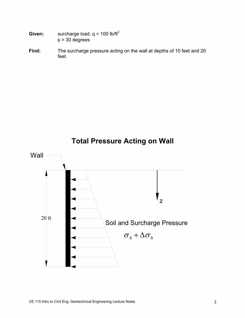
Given: surcharge load, q = 100 lb/ft2
φ = 30 degrees Find: The surcharge pressure acting on the wall at depths of 10 feet and 20
feet.
Total Pressure Acting on Wall
20 ft
z
Wall
Soil and Surcharge Pressure
hh σσ ∆+
CE 115 Intro to Civil Eng: Geotechnical Engineering Lecture Notes 4
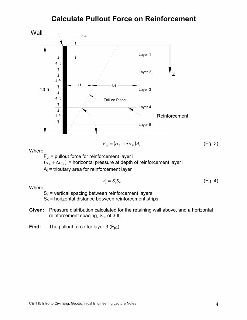
Calculate Pullout Force on Reinforcement
20 ft
z
Wall
Reinforcement
4 ft
4 ft
4 ft
2 ft
4 ft
Layer 1
Layer 2
Layer 3
Layer 4
Layer 5
Lf Le
Failure Plane
( ) thhpi AF σσ ∆+= (Eq. 3) Where: Fpi = pullout force for reinforcement layer i ( )hh σσ ∆+ = horizontal pressure at depth of reinforcement layer i At = tributary area for reinforcement layer
hvt SSA = (Eq. 4) Where Sv = vertical spacing between reinforcement layers Sh = horizontal distance between reinforcement strips Given: Pressure distribution calculated for the retaining wall above, and a horizontal
reinforcement spacing, Sh, of 3 ft, Find: The pullout force for layer 3 (Fp3)
CE 115 Intro to Civil Eng: Geotechnical Engineering Lecture Notes 5
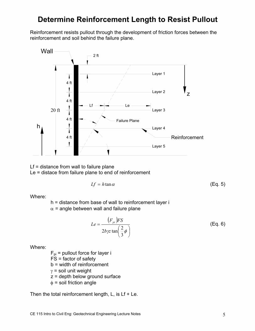
Determine Reinforcement Length to Resist Pullout Reinforcement resists pullout through the development of friction forces between the reinforcement and soil behind the failure plane.
20 ft
z
Wall
Reinforcement
4 ft
4 ft
4 ft
2 ft
4 ft
Layer 1
Layer 2
Layer 3
Layer 4
Layer 5
Lf Le
Failure Plane
h
Lf = distance from wall to failure plane Le = distace from failure plane to end of reinforcement
αtanhLf = (Eq. 5) Where: h = distance from base of wall to reinforcement layer i α = angle between wall and failure plane
( )
=φγ
32tan2 zb
FSFLe pi (Eq. 6)
Where: Fpi = pullout force for layer i FS = factor of safety b = width of reinforcement γ = soil unit weight z = depth below ground surface φ = soil friction angle Then the total reinforcement length, L, is Lf + Le.
CE 115 Intro to Civil Eng: Geotechnical Engineering Lecture Notes 6
Given: The retaining wall shown above, data from previous calculations (i.e. pullout
force), reinforcement with of 0.5 ft, and a factor of safety of 1.5 Find: The reinforcement length for layer 3
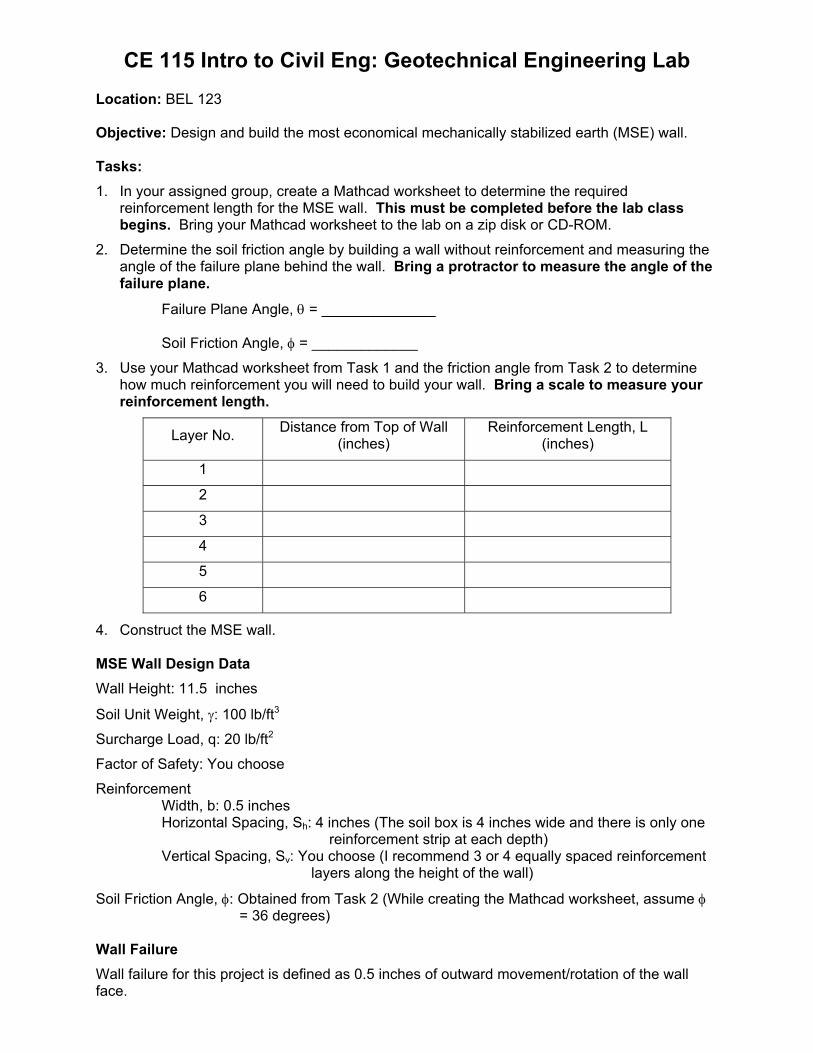
CE 115 Intro to Civil Eng: Geotechnical Engineering Lab Location: BEL 123 Objective: Design and build the most economical mechanically stabilized earth (MSE) wall. Tasks: 1. In your assigned group, create a Mathcad worksheet to determine the required
reinforcement length for the MSE wall. This must be completed before the lab class begins. Bring your Mathcad worksheet to the lab on a zip disk or CD-ROM.
2. Determine the soil friction angle by building a wall without reinforcement and measuring the angle of the failure plane behind the wall. Bring a protractor to measure the angle of the failure plane.
Failure Plane Angle, θ = ______________
Soil Friction Angle, φ = _____________
3. Use your Mathcad worksheet from Task 1 and the friction angle from Task 2 to determine how much reinforcement you will need to build your wall. Bring a scale to measure your reinforcement length.
Layer No. Distance from Top of Wall (inches)
Reinforcement Length, L (inches)
1
2
3
4
5
6
4. Construct the MSE wall. MSE Wall Design Data Wall Height: 11.5 inches
Soil Unit Weight, γ: 100 lb/ft3
Surcharge Load, q: 20 lb/ft2
Factor of Safety: You choose
Reinforcement Width, b: 0.5 inches Horizontal Spacing, Sh: 4 inches (The soil box is 4 inches wide and there is only one
reinforcement strip at each depth) Vertical Spacing, Sv: You choose (I recommend 3 or 4 equally spaced reinforcement
layers along the height of the wall)
Soil Friction Angle, φ: Obtained from Task 2 (While creating the Mathcad worksheet, assume φ = 36 degrees)
Wall Failure Wall failure for this project is defined as 0.5 inches of outward movement/rotation of the wall face.