
BNL/PBL SBIR Phase II HTS Program for approaching 40 T · A/mm2 A/mm(max)2 sec Ω A kV without 19 T...
26
BNL/PBL SBIR Phase II HTS Program for approaching 40 T Robert Weggel , David Cline, Alper Garren, Jim Kolonko, Ronald Scanlan PBL Ramesh Gupta , Mike Anerella, George Ganetis, Arup Ghosh, Harold Kirk, Robert Palmer, Steve Plate, William Sampson, Yuko Shiroyanagi, Peter Wanderer, Bruce Brandt BNL Seminar In FNAL Tech Division July 22, 2010 • Introduction to YBCO • BNL RIA/FRIB magnet • Muon Collider Requirements • SBIR Program Design • SBIR Program Progress • Conclusion See NFMCC-DOC-553 1
Transcript of BNL/PBL SBIR Phase II HTS Program for approaching 40 T · A/mm2 A/mm(max)2 sec Ω A kV without 19 T...
BNL/PBL SBIR Phase II HTS Programfor approaching 40 T
Robert Weggel, David Cline, Alper Garren, Jim Kolonko,Ronald Scanlan
PBLRamesh Gupta, Mike Anerella, George Ganetis, Arup Ghosh,Harold Kirk, Robert Palmer, Steve Plate, William Sampson,
Yuko Shiroyanagi, Peter Wanderer, Bruce BrandtBNL
Seminar In FNAL Tech Division July 22, 2010
• Introduction to YBCO
• BNL RIA/FRIB magnet
• Muon Collider Requirements
• SBIR Program Design
• SBIR Program Progress
• Conclusion
See NFMCC-DOC-553
1
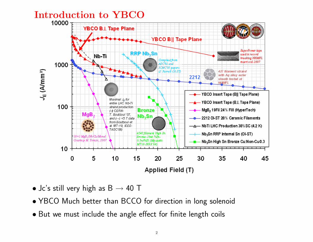
Introduction to YBCO
• Jc’s still very high as B → 40 T
• YBCO Much better than BCCO for direction in long solenoid
• But we must include the angle effect for finite length coils
2
But
• YBCO comes as single super-conducting layer 4-12 mm wide
• Currents will not flow uniformly over width
• Will have extreme ’magnetization’
• NOT suitable for normal accelerator quality dipoles or quadruples
• But suitable for:
1. Iron dominated magnetse.g Quadruples in very high radiation environments
2. Energy storage devicesno requirements on field details
3. Final Cooling solenoids for Muon Collidertracks follow field lines wherever they are
• Jc depends on angle between cable and fieldbut in a long solenoid the field is in the favorable direction
3
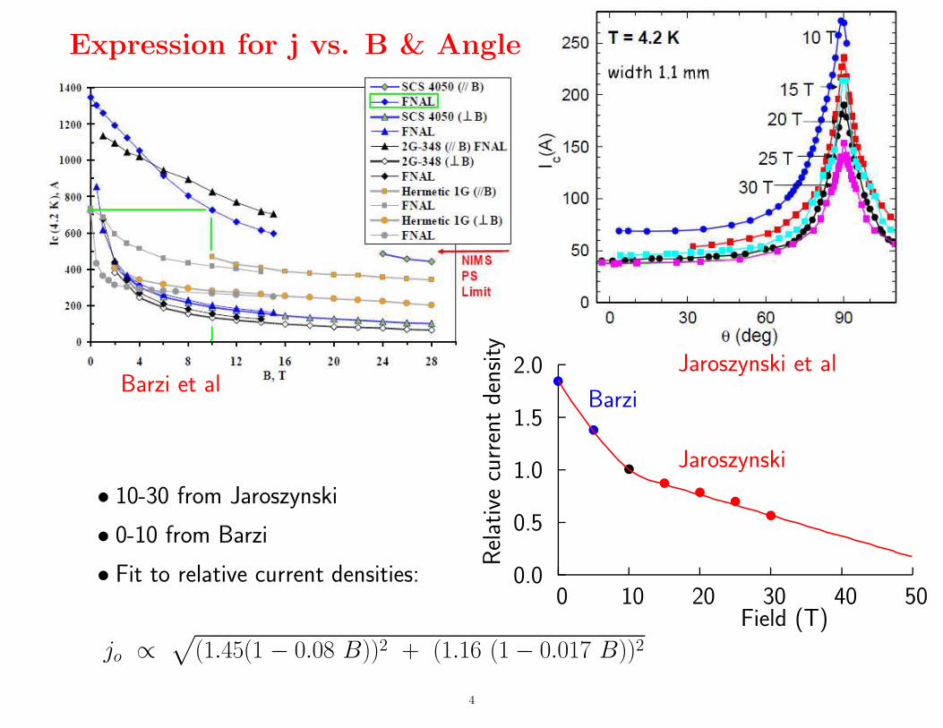
Expression for j vs. B & Angle
Barzi et alJaroszynski et al
• 10-30 from Jaroszynski
• 0-10 from Barzi
• Fit to relative current densities:
jo ∝√
(1.45(1 − 0.08 B))2 + (1.16 (1 − 0.017 B))2
Rel
ativ
ecu
rren
tde
nsity
Field (T)0 10 20 30 40 50
0.0
0.5
1.0
1.5
2.0
Barzi
Jaroszynski
•
•
•• • •
•
4
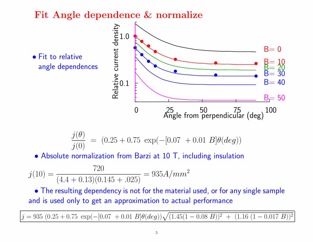
Fit Angle dependence & normalize
• Fit to relativeangle dependences
Rel
ativ
ecu
rren
tde
nsity
Angle from perpendicular (deg)0 25 50 75 100
0.1
1.0 ••••
•• •
••••
•• •
B= 0
B= 10B= 20B= 30B= 40
B= 50
j(θ)
j(0)= (0.25 + 0.75 exp(−[0.07 + 0.01 B]θ(deg))
• Absolute normalization from Barzi at 10 T, including insulation
j(10) =720
(4.4 + 0.13)(0.145 + .025)= 935A/mm2
• The resulting dependency is not for the material used, or for any single sampleand is used only to get an approximation to actual performance
j = 935 (0.25 + 0.75 exp(−[0.07 + 0.01 B]θ(deg))√
(1.45(1 − 0.08 B))2 + (1.16 (1 − 0.017 B))2
5
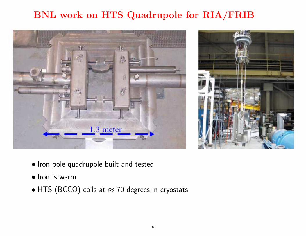
BNL work on HTS Quadrupole for RIA/FRIB
• Iron pole quadrupole built and tested
• Iron is warm
• HTS (BCCO) coils at ≈ 70 degrees in cryostats
6
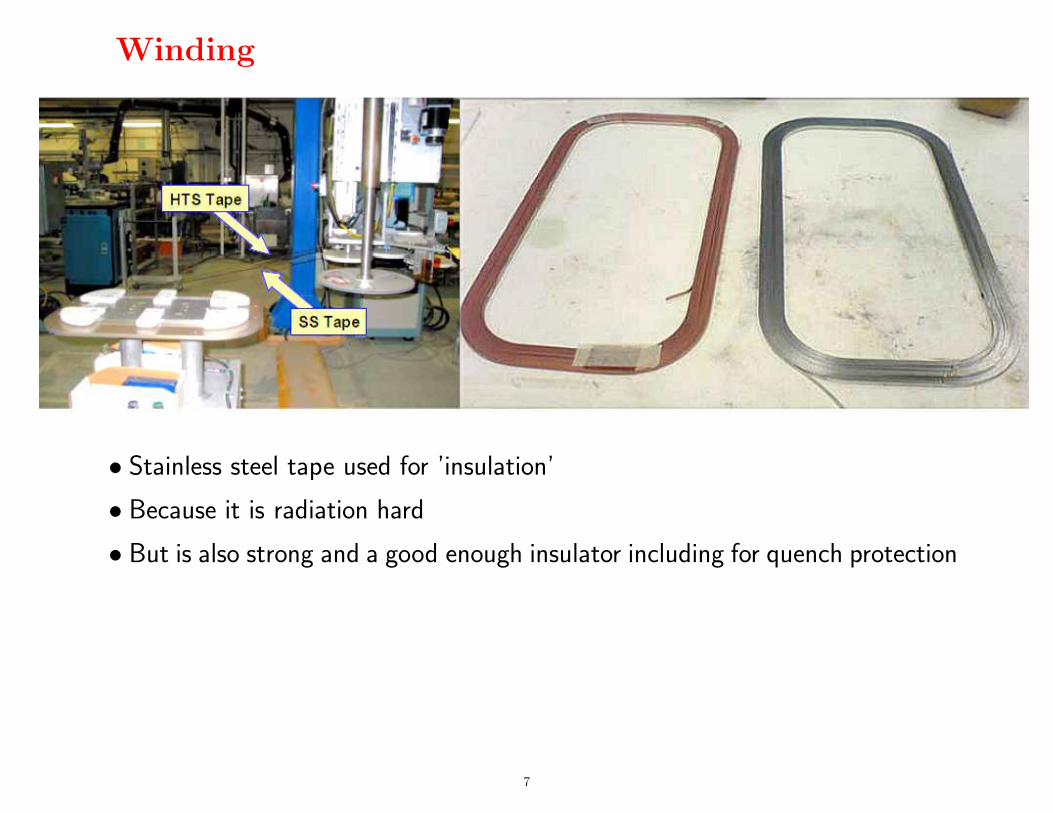
Winding
• Stainless steel tape used for ’insulation’
• Because it is radiation hard
• But is also strong and a good enough insulator including for quench protection
7
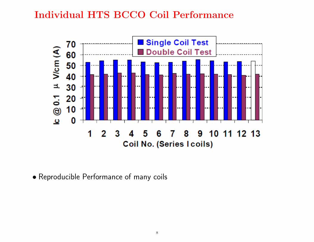
Individual HTS BCCO Coil Performance
• Reproducible Performance of many coils
8
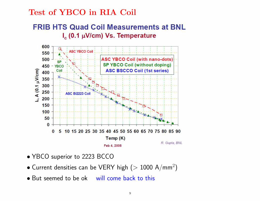
Test of YBCO in RIA Coil
• YBCO superior to 2223 BCCO
• Current densities can be VERY high (> 1000 A/mm2)
• But seemed to be ok will come back to this
9
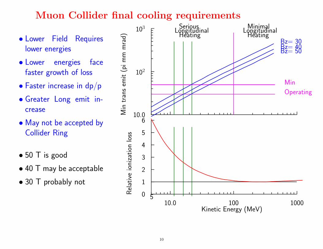
Muon Collider final cooling requirements
Min
tran
sem
it(p
im
mm
rad)
10.0
102
103 SeriousLongitudinal
HeatingMinimal
LongitudinalHeating
Min
Operating
Bz= 30Bz= 40Bz= 50
Rel
ativ
eio
niza
tion
loss
Kinetic Energy (MeV)
510.0 100 1000
0
1
2
3
4
5
6
• Lower Field Requireslower energies
• Lower energies facefaster growth of loss
• Faster increase in dp/p
• Greater Long emit in-crease
• May not be accepted byCollider Ring
• 50 T is good
• 40 T may be acceptable
• 30 T probably not
10
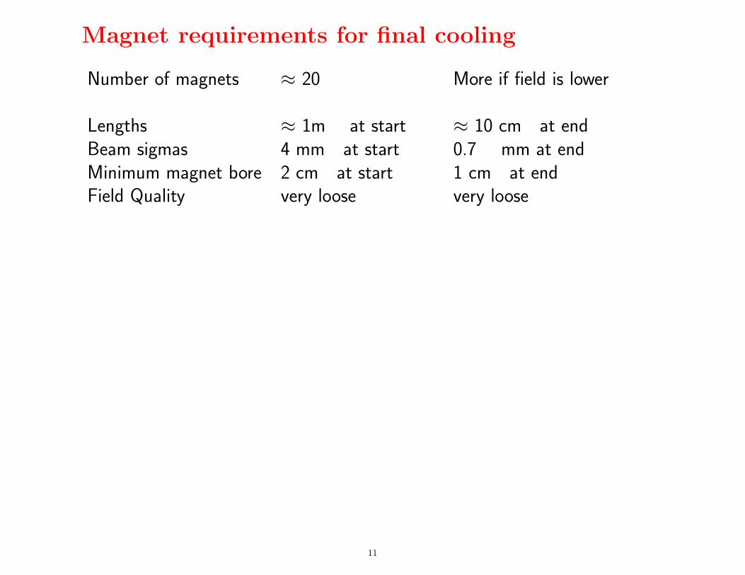
Magnet requirements for final cooling
Number of magnets ≈ 20 More if field is lower
Lengths ≈ 1m at start ≈ 10 cm at endBeam sigmas 4 mm at start 0.7 mm at endMinimum magnet bore 2 cm at start 1 cm at endField Quality very loose very loose
11
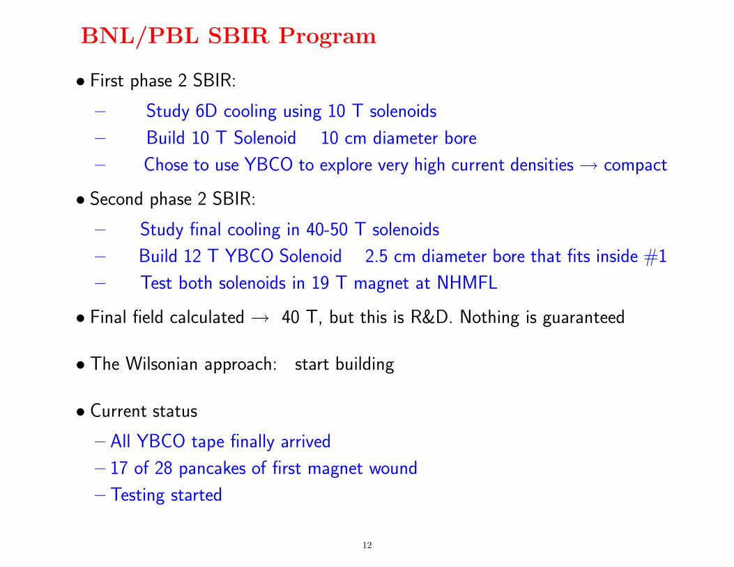
BNL/PBL SBIR Program
• First phase 2 SBIR:
– Study 6D cooling using 10 T solenoids
– Build 10 T Solenoid 10 cm diameter bore
– Chose to use YBCO to explore very high current densities → compact
• Second phase 2 SBIR:
– Study final cooling in 40-50 T solenoids
– Build 12 T YBCO Solenoid 2.5 cm diameter bore that fits inside #1
– Test both solenoids in 19 T magnet at NHMFL
• Final field calculated → 40 T, but this is R&D. Nothing is guaranteed
• The Wilsonian approach: start building
• Current status
– All YBCO tape finally arrived
– 17 of 28 pancakes of first magnet wound
– Testing started
12
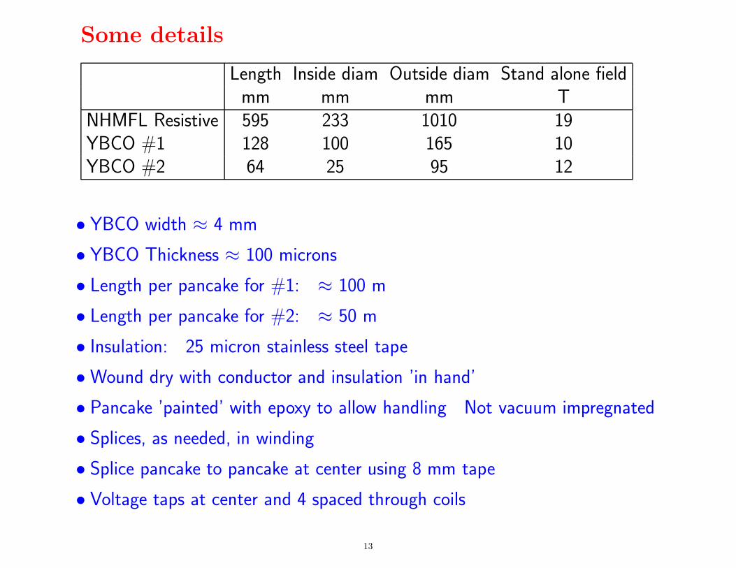
Some details
Length Inside diam Outside diam Stand alone fieldmm mm mm T
NHMFL Resistive 595 233 1010 19YBCO #1 128 100 165 10YBCO #2 64 25 95 12
• YBCO width ≈ 4 mm
• YBCO Thickness ≈ 100 microns
• Length per pancake for #1: ≈ 100 m
• Length per pancake for #2: ≈ 50 m
• Insulation: 25 micron stainless steel tape
• Wound dry with conductor and insulation ’in hand’
• Pancake ’painted’ with epoxy to allow handling Not vacuum impregnated
• Splices, as needed, in winding
• Splice pancake to pancake at center using 8 mm tape
• Voltage taps at center and 4 spaced through coils
13
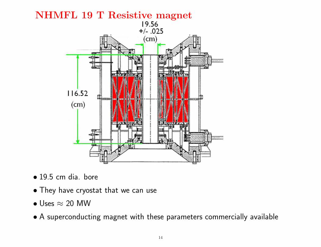
NHMFL 19 T Resistive magnet
• 19.5 cm dia. bore
• They have cryostat that we can use
• Uses ≈ 20 MW
• A superconducting magnet with these parameters commercially available
14
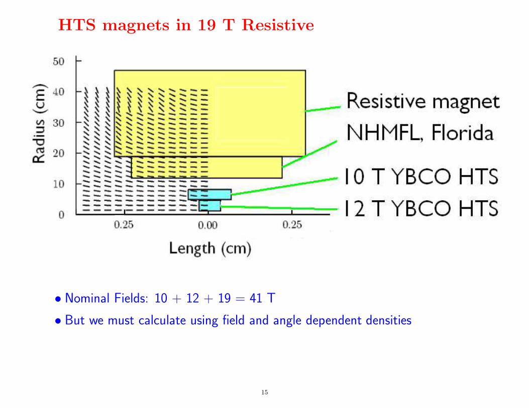
HTS magnets in 19 T Resistive
• Nominal Fields: 10 + 12 + 19 = 41 T
• But we must calculate using field and angle dependent densities
15

Maximum performance without resistive magnetra
dii
(cm
)
length (m)
438
0.000 0.025 0.050 0.0750.0
2.5
5.0
7.5
312
422 349 325 303
Axi
alFie
ld(T
)
0
10
20
30
40
radi
i(c
m)
length (m)0.000 0.025 0.050 0.075
0.0
2.5
5.0
7.5
10.0 max j/10 (A/mm2)
65 64 64 63 63 64 64 65 65 66 67 69 71 73 75 78 81 84 87 90 94 9710010310664 62 61 60 58 58 57 57 57 56 57 59 61 63 65 68 70 73 76 79 82 85 87 90 9363 60 58 55 53 52 51 50 49 47 48 50 53 55 57 60 62 65 68 70 73 75 77 80 8268 64 60 56 53 50 49 48 46 42 41 44 47 49 51 53 56 58 60 63 65 67 69 71 7366 61 57 52 48 46 44 42 40 37 37 40 42 44 46 48 51 53 55 57 58 60 62 64 6570 64 58 53 48 45 43 41 38 35 35 37 39 41 43 45 47 48 50 51 53 55 56 57 5974 67 60 54 48 44 42 40 37 34 33 35 37 38 40 42 43 45 46 47 49 50 51 52 5473 64 57 50 45 41 39 37 34 32 32 34 35 37 38 40 41 42 43 44 45 46 47 48 4977 67 59 51 45 41 39 37 34 32 31 33 34 36 37 38 39 39 40 41 42 42 43 45 4681 70 61 53 47 42 40 38 35 32 31 33 34 35 36 36 37 37 38 38 39 39 40 42 4379 67 58 50 44 40 38 36 34 31 32 33 34 35 35 35 36 36 35 36 36 37 38 39 4087 75 65 56 49 45 42 40 38 35 34 34 35 35 35 35 34 34 34 33 33 35 36 37 3984 71 61 52 46 42 40 38 36 35 34 34 34 33 33 32 32 31 31 30 31 33 34 36 3794 78 66 56 49 45 43 41 39 37 36 36 35 35 34 33 32 32 31 30 30 32 34 35 36106 83 67 56 48 44 43 41 39 38 37 36 35 35 34 33 32 32 31 30 30 32 33 35 36121 93 74 61 52 47 45 44 42 40 39 38 37 37 36 35 34 33 32 31 31 32 33 35 36110 76 58 48 43 40 39 38 37 36 36 35 35 34 33 33 32 32 31 30 31 32 34 35 36110 67 52 45 42 40 39 39 38 37 37 36 36 36 35 35 34 33 33 32 32 33 34 35 36117 72 55 48 44 42 41 41 40 39 39 38 38 37 36 36 35 35 34 33 33 34 35 36 36106 68 53 46 42 40 39 39 38 38 37 37 37 36 36 36 35 35 34 34 34 35 36 36 37128100 80 66 57 51 48 45 43 42 40 39 39 38 38 37 37 36 36 36 36 36 37 37 38
• Maximum current densities calculated from field and angles
• Current densities kept just below these for each of 12 blocks
• No margin included
graded not gradedCentral Field T 23.2 19.8Maximum current density A/mm2 438 342Maximum Stress MPa 235 155
16
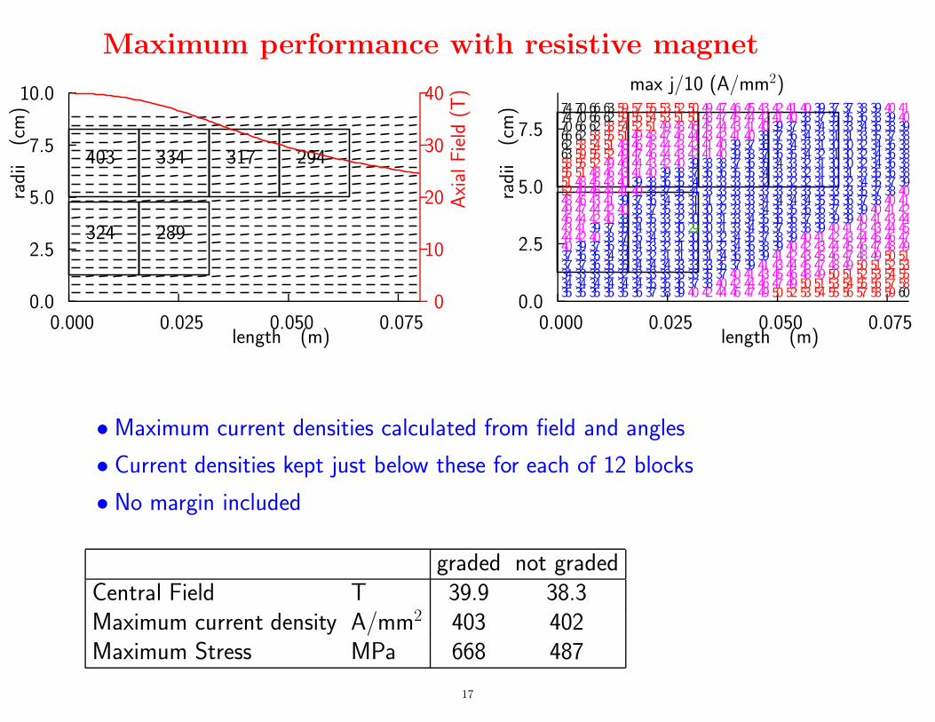
Maximum performance with resistive magnetra
dii
(cm
)
length (m)
324
0.000 0.025 0.050 0.0750.0
2.5
5.0
7.5
10.0
289
403 334 317 294
Axi
alFie
ld(T
)
0
10
20
30
40
radi
i(c
m)
length (m)0.000 0.025 0.050 0.075
0.0
2.5
5.0
7.5
max j/10 (A/mm2)
35 35 35 35 35 36 37 38 39 40 42 44 46 47 49 50 52 53 54 55 56 57 58 59 6034 34 34 34 34 34 35 35 36 37 38 40 42 44 46 47 49 50 51 53 54 55 56 57 5834 33 33 32 32 32 33 33 33 33 35 37 40 41 43 45 46 48 49 50 51 52 53 54 5537 37 36 35 35 34 34 34 33 33 33 35 37 39 41 43 44 45 47 48 49 50 51 52 5337 36 35 34 33 32 32 31 31 30 31 34 36 38 39 41 42 43 45 46 47 48 49 50 5140 39 37 36 35 34 33 32 31 30 30 32 34 36 38 39 40 42 43 44 45 46 47 48 4944 42 40 38 37 36 34 33 32 30 30 32 34 35 37 38 39 40 41 42 43 44 45 46 4743 41 39 37 35 34 33 32 30 29 30 31 33 34 36 37 38 38 39 40 41 42 43 44 4546 44 42 40 38 36 35 33 32 30 30 31 33 34 35 36 36 37 38 39 39 40 41 43 4449 47 44 42 40 38 37 35 33 31 30 32 33 33 34 35 35 36 36 37 38 39 40 41 4248 46 43 41 39 37 36 34 32 31 31 32 33 33 34 34 34 34 35 35 36 37 38 40 4152 49 46 44 41 40 38 37 35 34 33 33 33 33 33 33 33 33 33 33 33 35 37 38 4051 48 45 43 40 39 38 36 35 34 33 33 33 33 32 32 32 32 31 30 32 34 35 37 3955 51 48 46 43 41 40 39 38 37 36 36 35 35 34 33 33 32 31 30 31 33 35 36 3858 55 52 49 46 44 43 42 40 39 38 38 37 36 35 34 33 32 31 30 30 32 34 36 3863 59 55 52 49 47 46 44 43 42 41 40 39 38 37 36 35 34 32 31 30 32 34 36 3862 58 54 51 48 46 45 44 43 42 41 40 39 37 36 35 34 33 31 30 30 32 34 36 3866 62 58 55 51 49 48 47 46 44 43 42 41 40 38 37 36 34 33 31 31 33 35 37 3870 66 62 58 54 52 51 49 48 46 45 44 43 41 40 39 37 36 34 33 33 34 36 38 3974 70 66 62 59 56 54 53 51 50 48 47 45 44 42 41 40 38 37 35 35 36 38 39 4074 70 66 63 59 57 55 53 52 50 49 47 46 45 43 42 41 40 39 37 37 38 39 40 41
• Maximum current densities calculated from field and angles
• Current densities kept just below these for each of 12 blocks
• No margin included
graded not gradedCentral Field T 39.9 38.3Maximum current density A/mm2 403 402Maximum Stress MPa 668 487
17
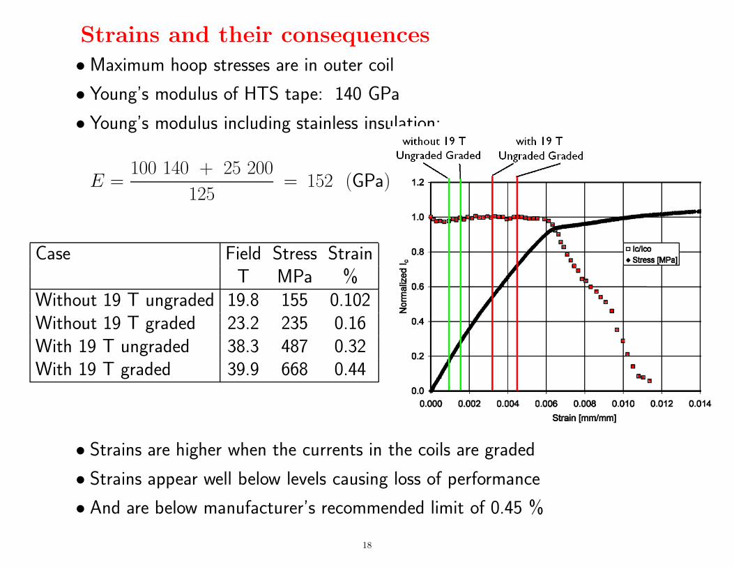
Strains and their consequences• Maximum hoop stresses are in outer coil
• Young’s modulus of HTS tape: 140 GPa
• Young’s modulus including stainless insulation:
E =100 140 + 25 200
125= 152 (GPa)
Case Field Stress StrainT MPa %
Without 19 T ungraded 19.8 155 0.102Without 19 T graded 23.2 235 0.16With 19 T ungraded 38.3 487 0.32With 19 T graded 39.9 668 0.44
• Strains are higher when the currents in the coils are graded
• Strains appear well below levels causing loss of performance
• And are below manufacturer’s recommended limit of 0.45 %
18
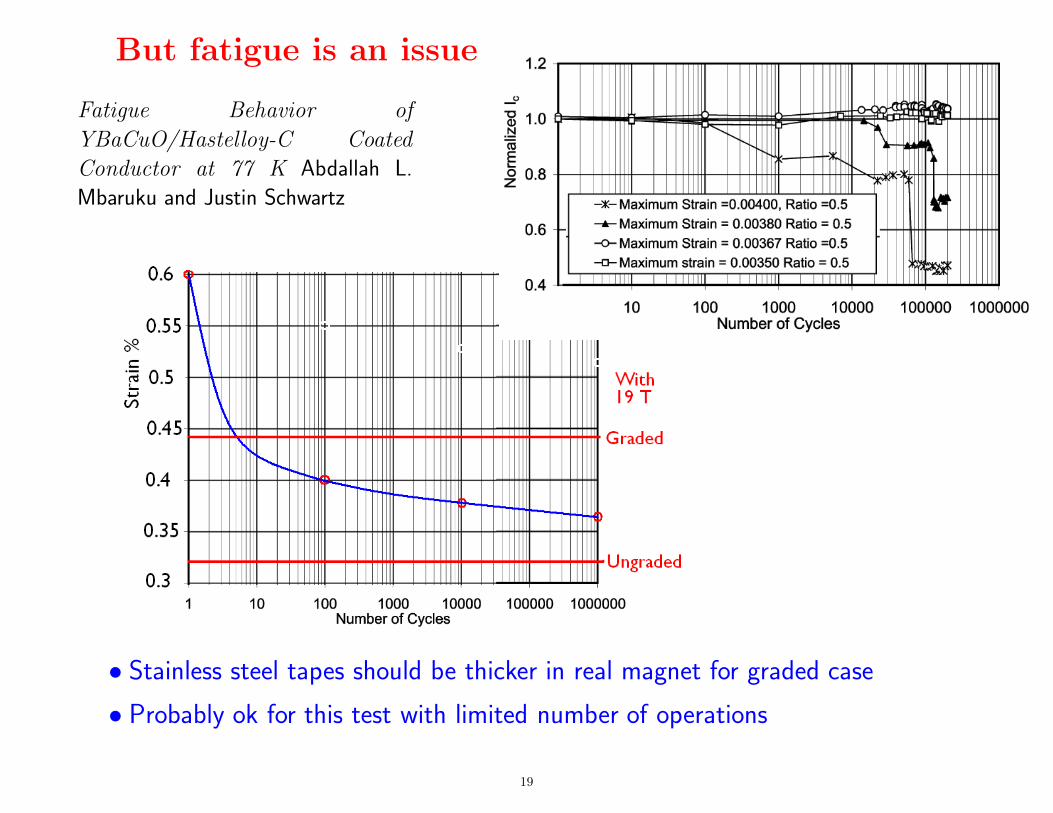
But fatigue is an issue
• Stainless steel tapes should be thicker in real magnet for graded case
• Probably ok for this test with limited number of operations
Fatigue Behavior of
YBaCuO/Hastelloy-C Coated
Conductor at 77 K Abdallah L.
Mbaruku and Justin Schwartz
19
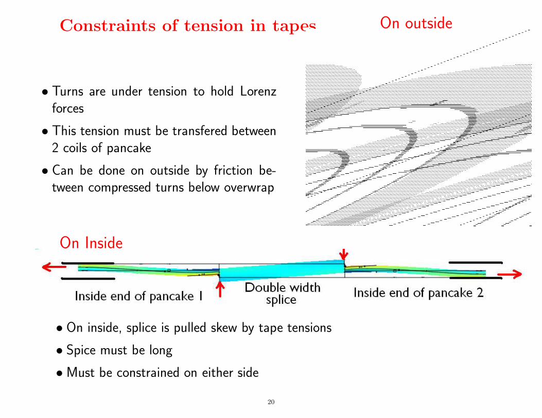
Constraints of tension in tapes On outside
• Turns are under tension to hold Lorenzforces
• This tension must be transfered between2 coils of pancake
• Can be done on outside by friction be-tween compressed turns below overwrap
On Inside
• On inside, splice is pulled skew by tape tensions
• Spice must be long
• Must be constrained on either side
20
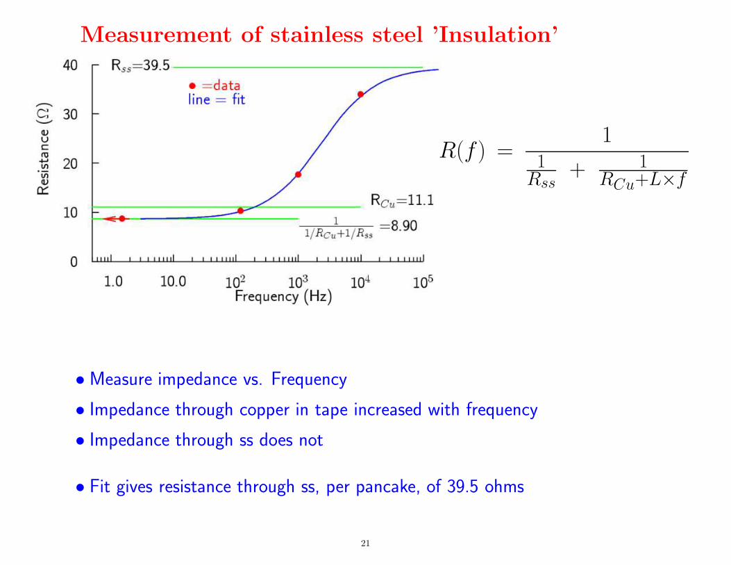
Measurement of stainless steel ’Insulation’
R(f ) =1
1Rss
+ 1RCu+L×f
• Measure impedance vs. Frequency
• Impedance through copper in tape increased with frequency
• Impedance through ss does not
• Fit gives resistance through ss, per pancake, of 39.5 ohms
21
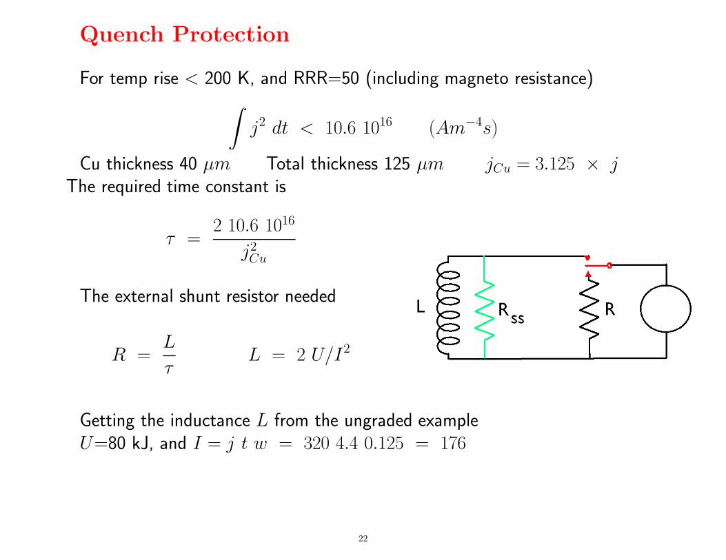
Quench Protection
For temp rise < 200 K, and RRR=50 (including magneto resistance)
∫
j2 dt < 10.6 1016 (Am−4s)
Cu thickness 40 µm Total thickness 125 µm jCu = 3.125 × jThe required time constant is
τ =2 10.6 1016
j2
Cu
The external shunt resistor needed
R =L
τL = 2 U/I2
Getting the inductance L from the ungraded exampleU=80 kJ, and I = j t w = 320 4.4 0.125 = 176
22
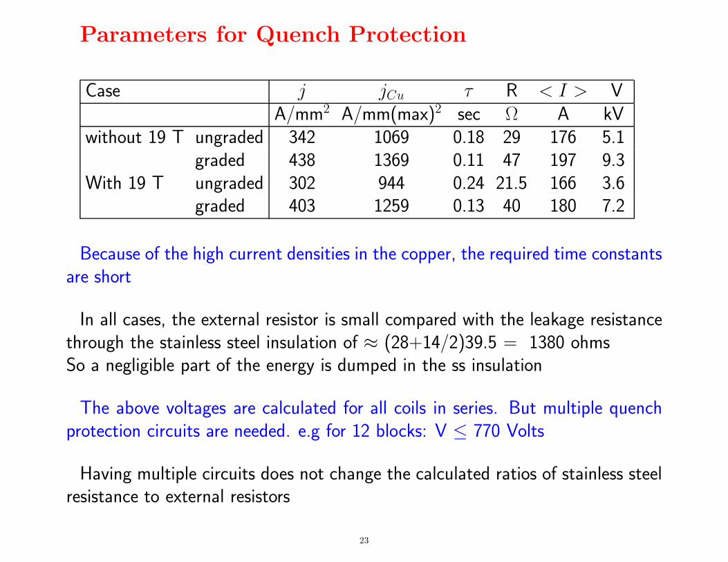
Parameters for Quench Protection
Case j jCu τ R < I > VA/mm2 A/mm(max)2 sec Ω A kV
without 19 T ungraded 342 1069 0.18 29 176 5.1graded 438 1369 0.11 47 197 9.3
With 19 T ungraded 302 944 0.24 21.5 166 3.6graded 403 1259 0.13 40 180 7.2
Because of the high current densities in the copper, the required time constantsare short
In all cases, the external resistor is small compared with the leakage resistancethrough the stainless steel insulation of ≈ (28+14/2)39.5 = 1380 ohmsSo a negligible part of the energy is dumped in the ss insulation
The above voltages are calculated for all coils in series. But multiple quenchprotection circuits are needed. e.g for 12 blocks: V ≤ 770 Volts
Having multiple circuits does not change the calculated ratios of stainless steelresistance to external resistors
23
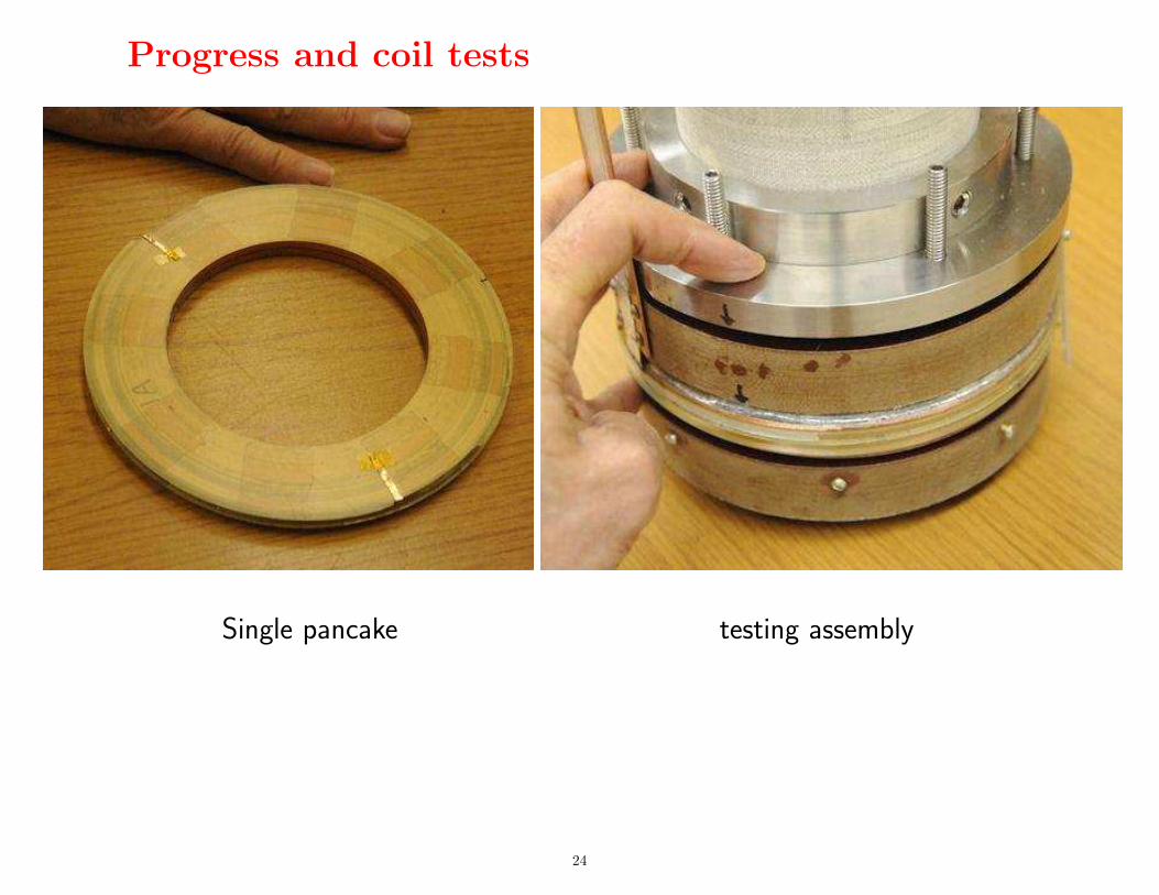
Progress and coil tests
Single pancake testing assembly
24
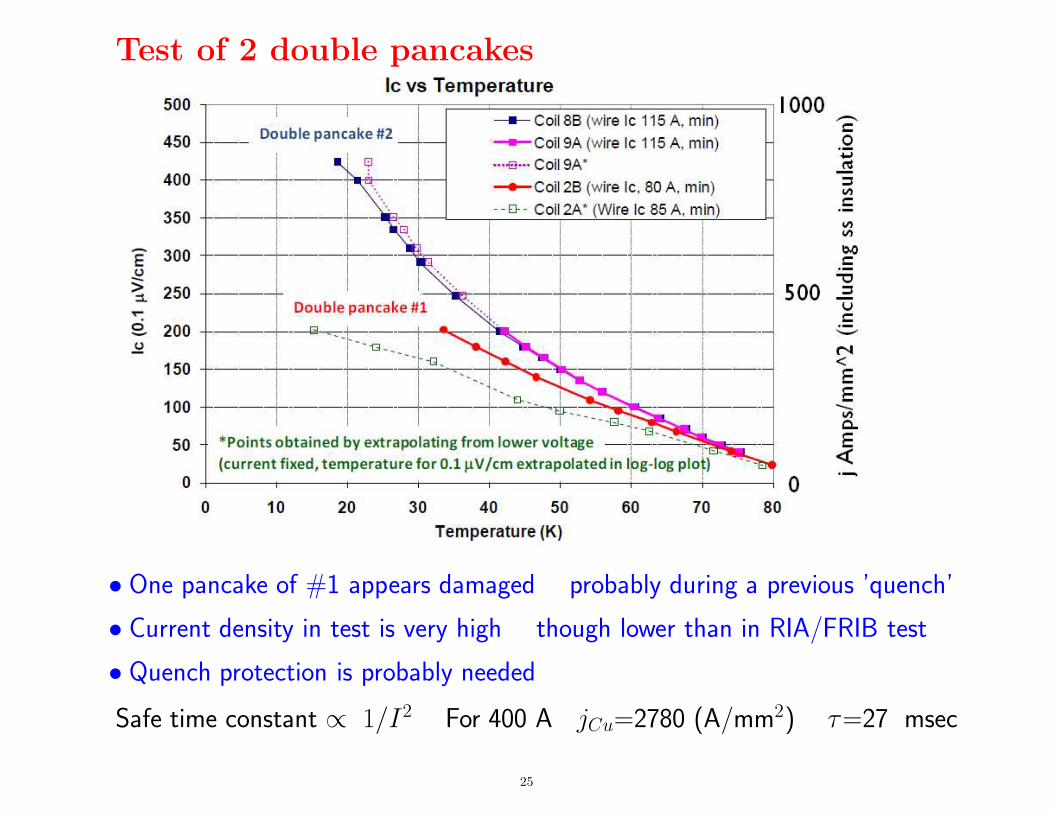
Test of 2 double pancakes
• One pancake of #1 appears damaged probably during a previous ’quench’
• Current density in test is very high though lower than in RIA/FRIB test
• Quench protection is probably needed
Safe time constant ∝ 1/I2 For 400 A jCu=2780 (A/mm2) τ=27 msec
25
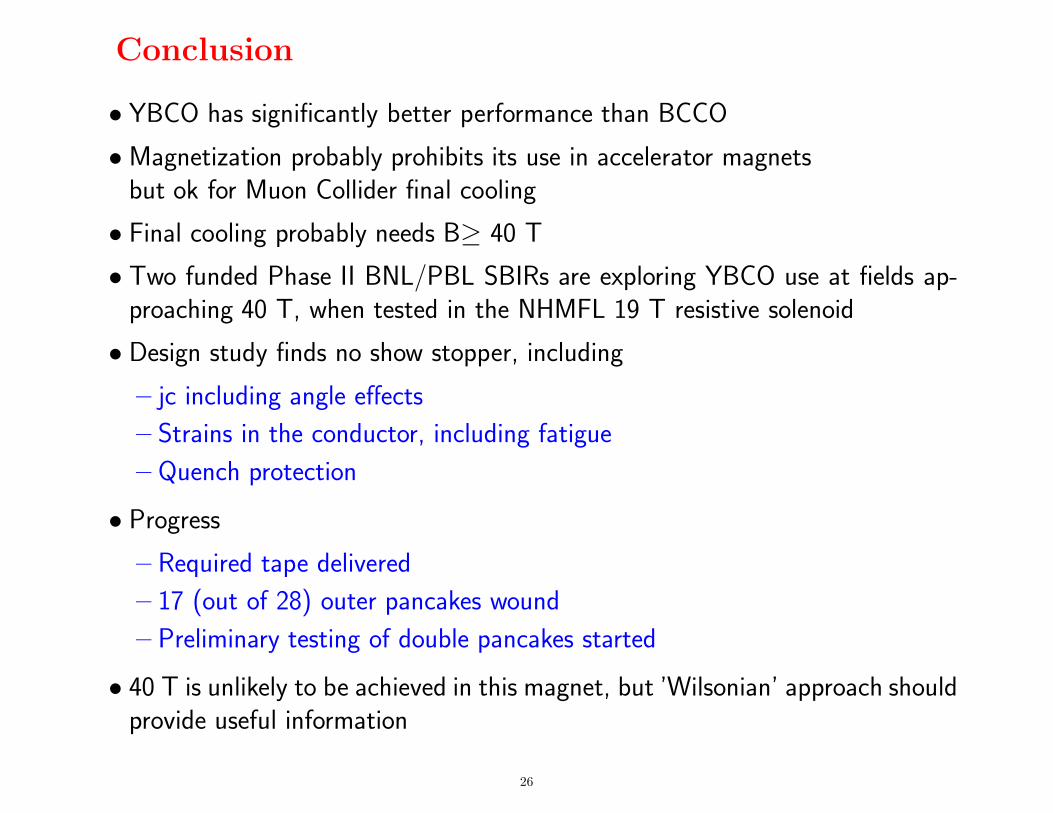
Conclusion
• YBCO has significantly better performance than BCCO
• Magnetization probably prohibits its use in accelerator magnetsbut ok for Muon Collider final cooling
• Final cooling probably needs B≥ 40 T
• Two funded Phase II BNL/PBL SBIRs are exploring YBCO use at fields ap-proaching 40 T, when tested in the NHMFL 19 T resistive solenoid
• Design study finds no show stopper, including
– jc including angle effects
– Strains in the conductor, including fatigue
– Quench protection
• Progress
– Required tape delivered
– 17 (out of 28) outer pancakes wound
– Preliminary testing of double pancakes started
• 40 T is unlikely to be achieved in this magnet, but ’Wilsonian’ approach shouldprovide useful information
26


![;T arXiv:2004.12155v2 [hep-ph] 23 May 2020 · L;T R toSM,whichisdubbed asVLQTmodel. TheLagrangiancanbewrittenas[21] L= L SM+ LYukawa T + L gauge T; LYukawa T = i T Q i L eT R M T](https://static.fdocument.org/doc/165x107/5fc6f89706f746179e1ee992/t-arxiv200412155v2-hep-ph-23-may-2020-lt-r-tosmwhichisdubbed-asvlqtmodel.jpg)