Background: Coordinate System Transformations. i j Derivation of the 2D Rotation Matrix (basis...
43
Background: Coordinate System Transformations
-
Upload
reynold-hodges -
Category
Documents
-
view
224 -
download
1
Transcript of Background: Coordinate System Transformations. i j Derivation of the 2D Rotation Matrix (basis...

Background:Coordinate System Transformations
i
j
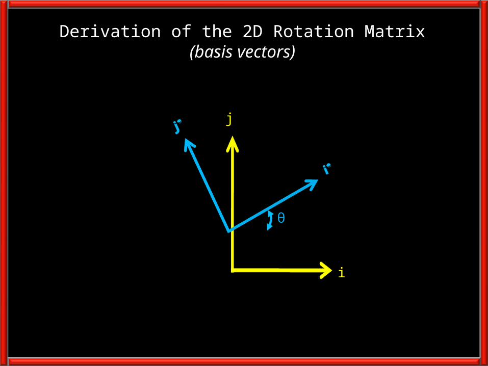
Derivation of the 2D Rotation Matrix(basis vectors)
θ

𝑖Ƹ′
i
j
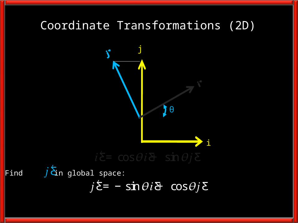
Coordinate Transformations (2D)
θ
𝑖Ƹ′ = cos𝜃𝑖Ƹ+ sin𝜃𝑗Ƹ Find in global space:
i
j
Coordinate Transformations (2D)
θ
𝑖Ƹ′ = cos𝜃𝑖Ƹ+ sin𝜃𝑗Ƹ 𝑗Ƹ′ = −sin𝜃𝑖Ƹ+ cos𝜃𝑗Ƹ 𝑗Ƹ′
Find in global space:

Coordinate Transformations
𝑖Ƹ′ = cos𝜃𝑖Ƹ+ sin𝜃𝑗Ƹ 𝑗Ƹ′ = −sin 𝜃𝑖Ƹ+ cos𝜃𝑗Ƹ 𝑖Ƹ′𝑗Ƹ′൨= ቚcos𝜃 sin𝜃−sin𝜃 cos𝜃ቚ𝑖Ƹ𝑗Ƹ൨
Note: The rows of the 2x2 rotation matrix from global to local space are composedof the unit vectors of the local coordinate system axis (in global space).
i
j
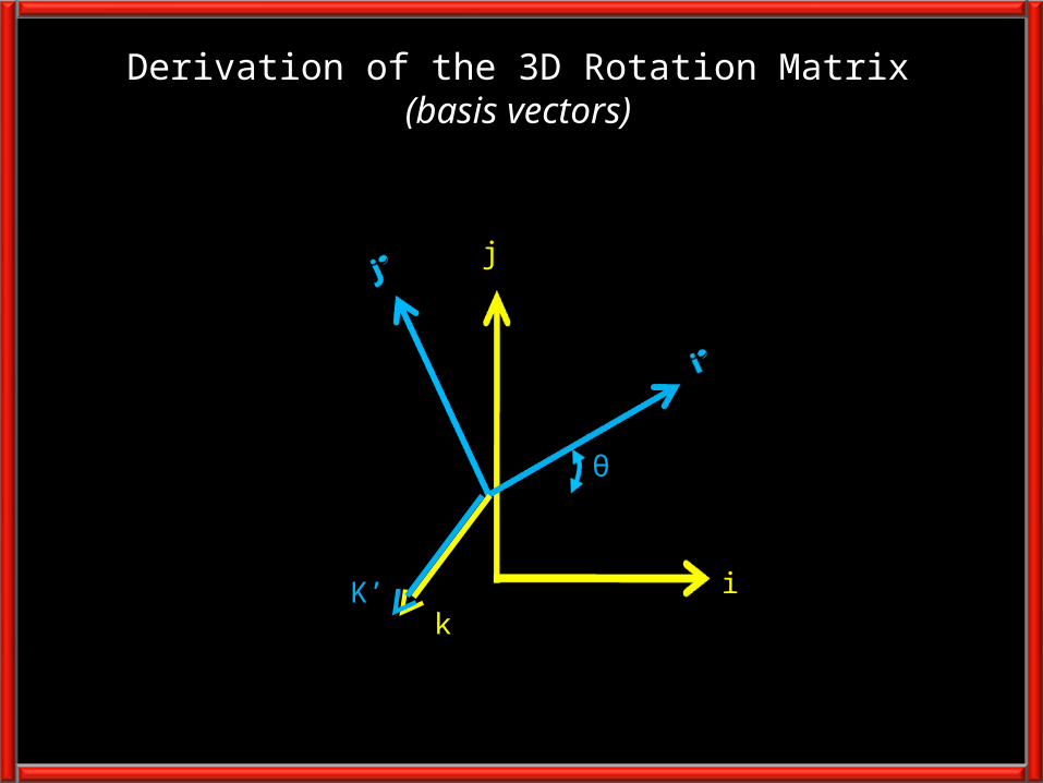
Derivation of the 3D Rotation Matrix(basis vectors)
θ
kK’
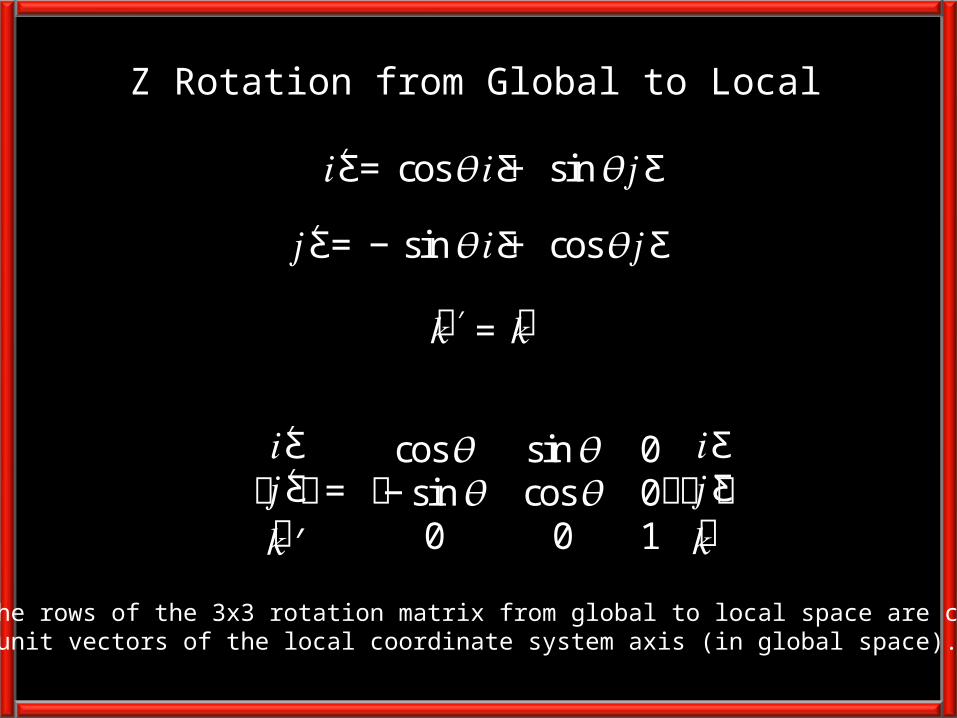
Z Rotation from Global to Local
𝑖Ƹ′𝑗Ƹ′𝑘′൩= อcos𝜃 sin𝜃 0−sin𝜃 cos𝜃 00 0 1อ𝑖Ƹ𝑗Ƹ𝑘൩
𝑖Ƹ′ = cos𝜃𝑖Ƹ+ sin𝜃𝑗Ƹ 𝑗Ƹ′ = −sin𝜃𝑖Ƹ+ cos𝜃𝑗Ƹ 𝑘 ′ = 𝑘
Note: The rows of the 3x3 rotation matrix from global to local space are composedof the unit vectors of the local coordinate system axis (in global space).
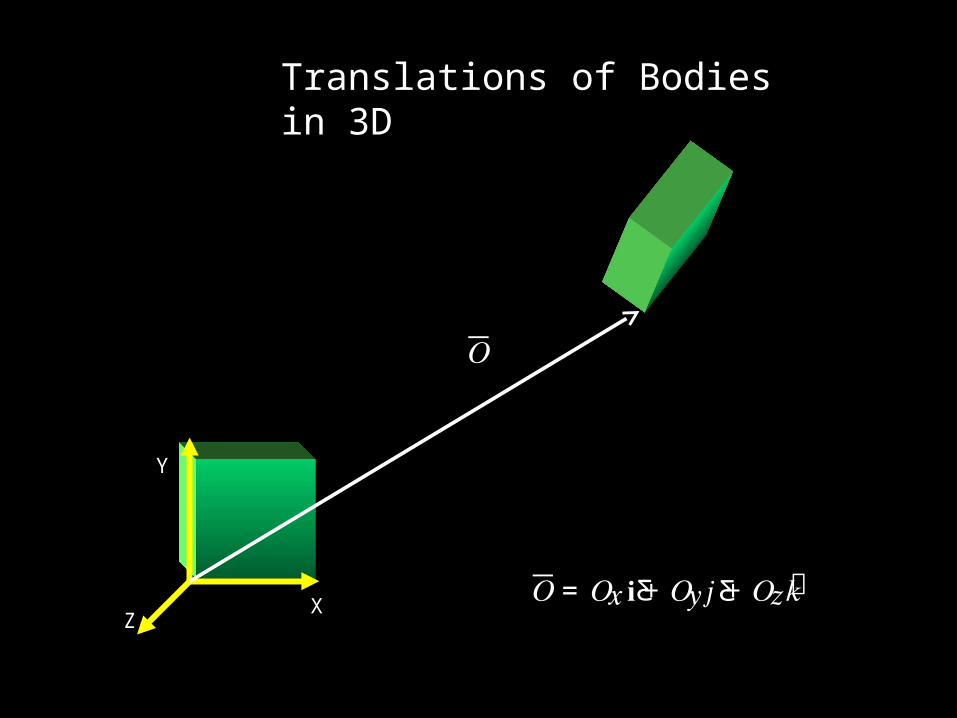
Translations of Bodies in 3D
Y
XZ
𝑂= 𝑂𝑥𝐢Ƹ+ 𝑂𝑦𝑗Ƹ+ 𝑂𝑧𝑘
𝑂

Y
XZ
𝑂
𝑃′ = 𝑅(𝑃ത− 𝑂)
X’
z’y’
P
P’P’
Coordinate System Transformations(Global to Local example)

Translations and Rotation(Example: Global to Local)
Y
XZ
X
Y
Z
For:
andOx=8, Oy=8, Oz=0
Find P in Local Space (P’)?
O
P 𝑅 = อ1 0 00 .707 .7070 −.707 .707อ
𝑃ത= 10𝐢Ƹ + 9.41𝑗Ƹ + 1.41𝑘 P’

Coordinate System Transformations(Example: Global to Local)
Y
XZ
X
Y
Z
Transform global to local:
ቮ
𝑃𝑥′𝑃𝑦′𝑃𝑧′ቮ= อ1 0 00 .707 .7070 −.707 .707อ อ
109.411.41อ− อ880อ ൩
𝑃ത′ = 𝑅(𝑃തതത− 𝑂)
= อ220อ ቮ
𝑃𝑥′𝑃𝑦′𝑃𝑧′ቮ= อ1 0 00 .707 .7070 −.707 .707ออ
21.411.41อ ൩
𝑃ത= 10𝐢Ƹ + 9.41𝑗Ƹ + 1.41𝑘 P’

Rotation Matrices are orthonormal
• The rotation from Global to Local Spaceis the inverse of the rotation from Local to Global Space
• Rotation Matrices are orthonormal and thusthe inverse is equal to the transpose
𝑅𝑅′ = 𝐼
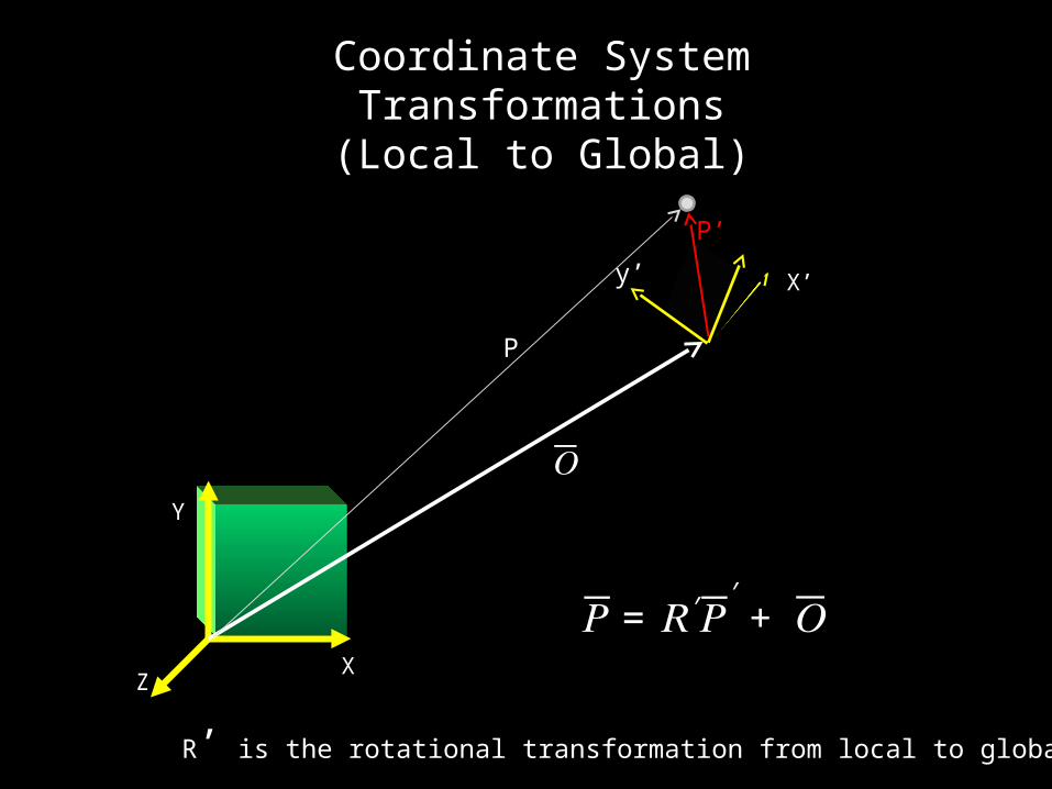
Coordinate System Transformations(Local to Global)
Y
XZ
𝑂
𝑃= 𝑅′𝑃′ + 𝑂
X’
z’y’
P
P’P’
R’ is the rotational transformation from local to global space

Y
XZ
X
Y
Z
For:
andOx=8, Oy=8, Oz=0
Find P in Global Space
𝑃ത′ = 2𝐢Ƹ′ + 2𝑗Ƹ′ + 0𝑘 ′
O
P 𝑅 = อ1 0 00 .707 .7070 −.707 .707อ
P’
Coordinate System Transformations(Example: Local to Global)

Y
XZ
X
Y
ZTransform local to global:
ተ
𝑃𝑥𝑃𝑦𝑃𝑧ተ= อ
1 0 00 .707 −.7070 .707 .707 ออ220อ + อ
880อ
= อ109.411.41อ
𝑃= 𝑅′𝑃′ + 𝑂
𝑃ത′ = 2𝐢Ƹ′ + 2𝑗Ƹ′ + 0𝑘 ′
ተ
𝑃𝑥𝑃𝑦𝑃𝑧ተ= อ
21.411.41อ + อ880อ
Coordinate System Transformations(Example: Local to Global)
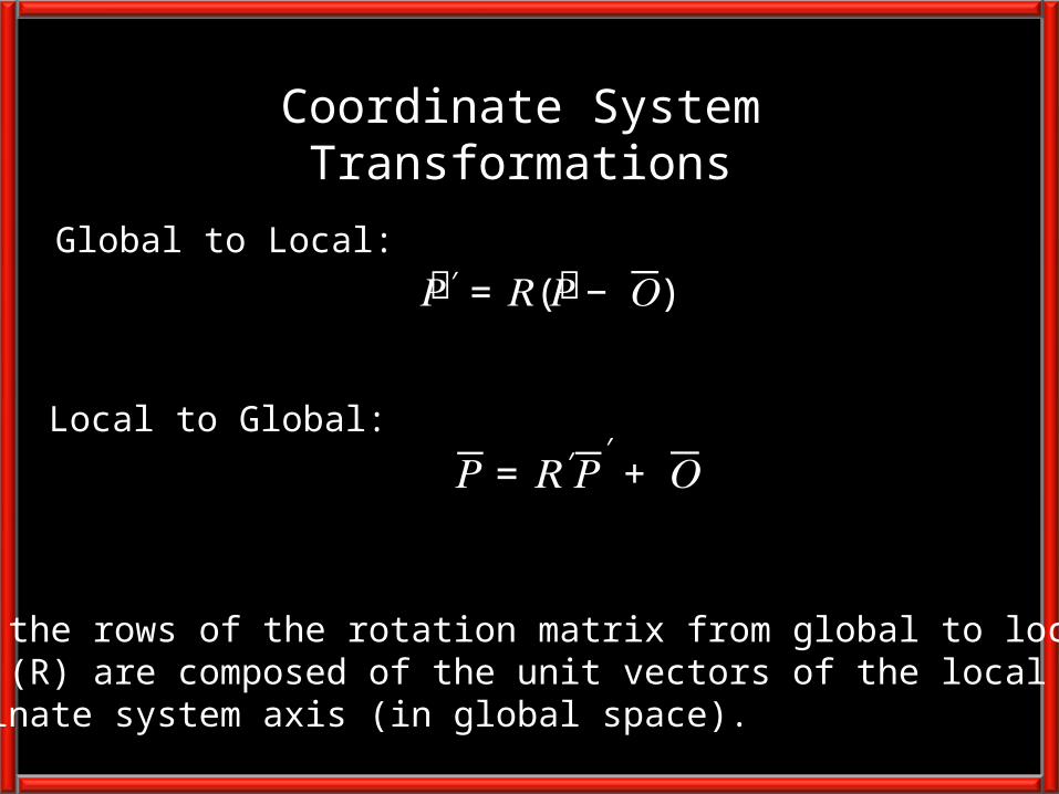
Coordinate System Transformations
Global to Local:
Local to Global:
𝑃ത′ = 𝑅(𝑃ത− 𝑂)
𝑃= 𝑅′𝑃′ + 𝑂
Where the rows of the rotation matrix from global to local space (R) are composed of the unit vectors of the local coordinate system axis (in global space).
Non-Optimal Pose Estimation

Pelvis

Anatomical Coordinate Systems (pelvis)How to calculate the anatomical coordinate systems
3) Create M/L Unit Vector i from step 2unit vector = (ix, iy, iz)
4) Find the vector from the Sacrum toOrigin
1) Find midpt between LASIS & RASIS = Origin
5) Create Unit Vector v from step 4unit vector = (vx, v, vz)
6) Use i X v to get Inferior/Superior Unit Vectorunit vector = (kx, ky, kz)
7) Use k X i to get Anterior/Posterior Unit Vectorunit vector = (jx, jy, jz)
𝑅𝑝𝑒𝑙𝑣𝑖𝑠 = ቮ
𝑖𝑥 𝑖𝑦 𝑖𝑧𝑗𝑥 𝑗𝑦 𝑗𝑧𝑘𝑥 𝑘𝑦 𝑘𝑧ቮ
X
Z
Y2) Find the vector from Origin to right ASIS

Finding the Hip Center(in Pelvic Coordinate System)
X
Z
Y
Right Hip (Bell, Brand and Pederson):
X = 0.36 * ASIS DistanceY = -0.19 * ASIS DistanceZ = -0.30 * ASIS Distance

Pelvis Non-Optimal Calibration:
• Finding the local coordinates of the hip center (which are needed to calibrate the other segments)
• Anthropometrics, Graphics Scaling and Graphing the Calibration Trial

Pelvis: code is already partof GaitProject

Thigh
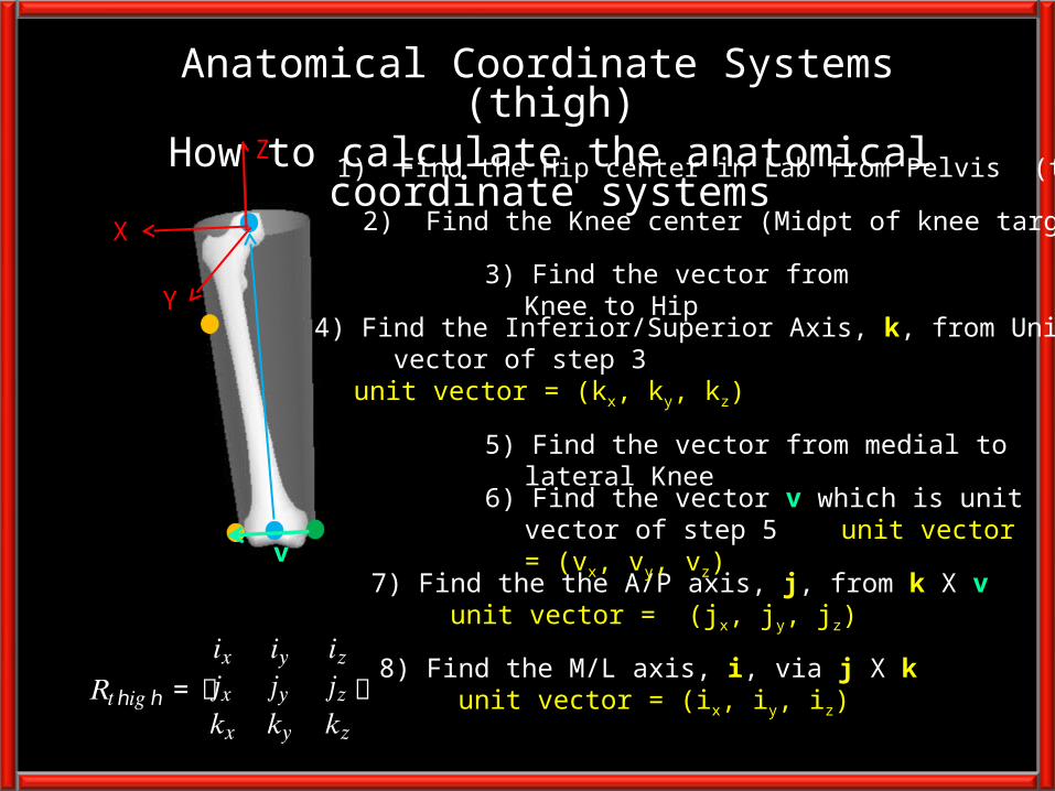
Anatomical Coordinate Systems (thigh)How to calculate the anatomical coordinate systems
2) Find the Knee center (Midpt of knee targets)
3) Find the vector from Knee to Hip
7) Find the the A/P axis, j, from k X v unit vector = (jx, jy, jz)
8) Find the M/L axis, i, via j X k unit vector = (ix, iy, iz)
𝑅𝑡ℎ𝑖𝑔ℎ = ቮ
𝑖𝑥 𝑖𝑦 𝑖𝑧𝑗𝑥 𝑗𝑦 𝑗𝑧𝑘𝑥 𝑘𝑦 𝑘𝑧ቮ
1) Find the Hip center in Lab from Pelvis (tricky)
4) Find the Inferior/Superior Axis, k, from Unit vector of step 3
unit vector = (kx, ky, kz)
5) Find the vector from medial to lateral Knee
6) Find the vector v which is unit vector of step 5unit vector = (vx, vy, vz)
v
Z
X
Y

Problem: Calculating the anatomical coordinate system requires a target (medial knee) not used during the
walking trial

Solution: Create a virtual medial knee target which can be located during
the motion trials
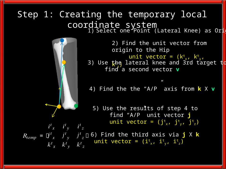
Step 1: Creating the temporary local coordinate system
1) Select one Point (Lateral Knee) as Origin
2) Find the unit vector from origin to the Hip unit vector = (kt
x, kty, kt
z)
3) Use the lateral knee and 3rd target to find a second vector v
6) Find the third axis via j X k unit vector = (it
x, ity, it
z) 𝑅𝑡𝑒𝑚𝑝 = ተ
𝑖𝑡𝑥 𝑖𝑡𝑦 𝑖𝑡𝑧𝑗𝑡𝑥 𝑗𝑡𝑦 𝑗𝑡𝑧𝑘𝑡𝑥 𝑘𝑡𝑦 𝑘𝑡𝑧ተ
5) Use the results of step 4 to find “A/P” unit vector j unit vector = (jt
x, jty, jt
z)
4) Find the the “A/P” axis from k X v

Step 2: Storing the virtual lateral knee target
1) Start with the tracking based local coordinate system (Rtemp)
P
2) Transform P into the tracking coordinatesystem (P’) using
‘
𝑃′ = 𝑹𝒕𝒆𝒎𝒑 (𝑃ത− 𝑂ത)
Where P are the global coordinates of lat knee and O are the global coordinates of the medial knee
Thigh Non-Optimal Calibration:
• Finding the local coordinates of the medial knee target in the calibration trial
• Anthropometrics, Graphics Scaling and Graphing the Calibration Trial

1) Create the tracking based local coordinate system (Rtemp)
2) Recall the stored vector (P’) fromorigin to the calibration target (in tracking coordinate system)
P
3) Transform P’ into the global coordinatesystem (P) using:
‘𝑃= 𝑹𝒕𝒆𝒎𝒑′𝑃′ + 𝑶
4) Use the tracking targets (including virtual) to find anatomically basedcoordinate system
Step 3: Find the anatomical system during movement

Thigh: code is already partof GaitProject

Shank
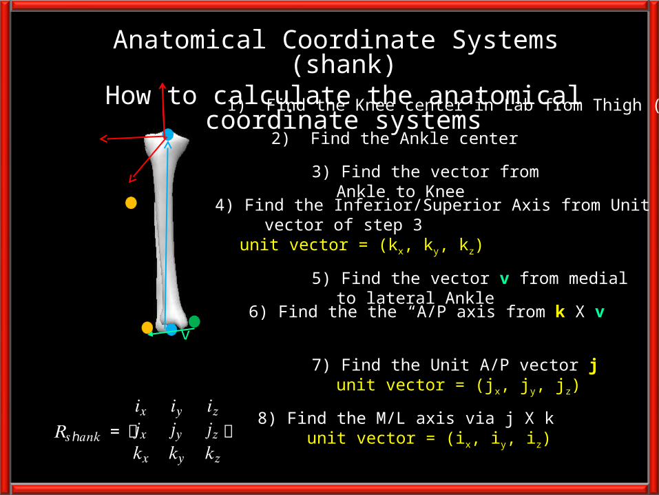
Anatomical Coordinate Systems (shank)How to calculate the anatomical coordinate systems
2) Find the Ankle center
3) Find the vector from Ankle to Knee
6) Find the the “A/P axis from k X v
8) Find the M/L axis via j X k unit vector = (ix, iy, iz)
𝑅𝑠ℎ𝑎𝑛𝑘 = ቮ
𝑖𝑥 𝑖𝑦 𝑖𝑧𝑗𝑥 𝑗𝑦 𝑗𝑧𝑘𝑥 𝑘𝑦 𝑘𝑧ቮ
1) Find the Knee center in Lab from Thigh (tricky)
4) Find the Inferior/Superior Axis from Unit vector of step 3
unit vector = (kx, ky, kz)
5) Find the vector v from medial to lateral Ankle
7) Find the Unit A/P vector junit vector = (jx, jy, jz)
v
Problem: Calculating the anatomical coordinate system requires a target (medial ankle) not used during the
walking trial
Solution: Create a virtual medial ankle target which can be located
during the motion trials
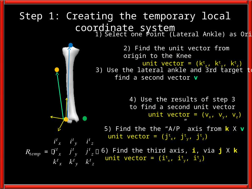
Step 1: Creating the temporary local coordinate system
1) Select one Point (Lateral Ankle) as Origin
2) Find the unit vector from origin to the Knee unit vector = (kt
x, kty, kt
z)
3) Use the lateral ankle and 3rd target to find a second vector v
6) Find the third axis, i, via j X k unit vector = (it
x, ity, it
z) 𝑅𝑡𝑒𝑚𝑝 = ተ
𝑖𝑡𝑥 𝑖𝑡𝑦 𝑖𝑡𝑧𝑗𝑡𝑥 𝑗𝑡𝑦 𝑗𝑡𝑧𝑘𝑡𝑥 𝑘𝑡𝑦 𝑘𝑡𝑧ተ
4) Use the results of step 3 to find a second unit vector unit vector = (vx, vy, vz)
5) Find the the “A/P” axis from k X v unit vector = (jt
x, jty, jt
z)

Step 2: Storing the virtual lateral ankle target
1) Start with the tracking based local coordinate system (Rtemp)
P
2) Transform P into the tracking coordinatesystem (P’) using
‘
𝑃′ = 𝑹𝒕𝒆𝒎𝒑 (𝑃ത− 𝑂ത)
Where P are the global coordinates of lat ankle and O are the global coordinates of the medial ankle
Shank Non-Optimal Calibration:
• Finding the local coordinates of the medial ankle target in the calibration trial
• Anthropometrics, Graphics Scaling and Graphing the Calibration Trial
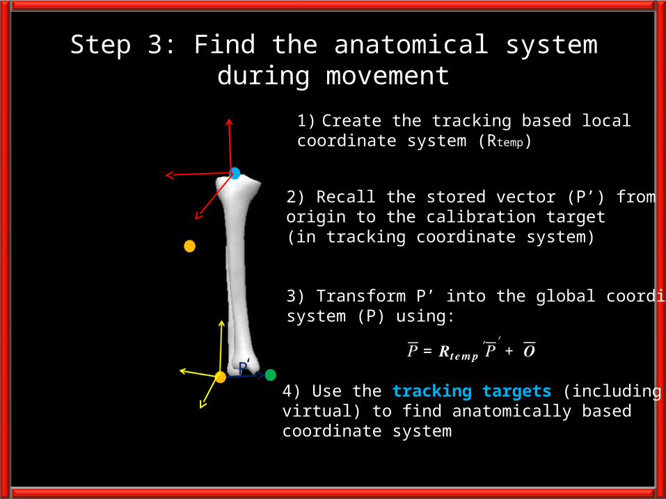
1) Create the tracking based local coordinate system (Rtemp)
2) Recall the stored vector (P’) fromorigin to the calibration target (in tracking coordinate system)
P
3) Transform P’ into the global coordinatesystem (P) using:
‘𝑃= 𝑹𝒕𝒆𝒎𝒑′𝑃′ + 𝑶
4) Use the tracking targets (including virtual) to find anatomically basedcoordinate system
Step 3: Find the anatomical system during movement

Foot

Anatomical Coordinate Systems (foot)How to calculate the anatomical coordinate systems
3) Find Z Axis from Unit vector of step 1unit vector = (kx, ky, kz)
4) Find the vector from Origin to Heel v
7) Find the the Y axis, j, from k X i unit vector = (kx, ky, kz)
6) Find the unit vector from step 2 unit vector = (ix, iy, iz)
𝑅𝑓𝑜𝑜𝑡 = ቮ
𝑖𝑥 𝑖𝑦 𝑖𝑧𝑗𝑥 𝑗𝑦 𝑗𝑧𝑘𝑥 𝑘𝑦 𝑘𝑧ቮ
2) Find the Vector from Toe to Origin
5) Find the M/L axis via k X v
Y
Z
X
1) Find midpoint of ankle targets = Origin (from Shank - tricky)
Foot Non-Optimal Calibration:
Anthropometrics, Graphics Scaling and Graphing the Calibration Trial

Assignment #5 – Build Non Optimal Model in Gait Project for the right thigh, right shank and
right foot
Let’s Look at the Pelvis and Thigh Code right now