
Assignment 2 1. - Nc State University · 2010-03-29 · Plugging in the numbers we note that the...
9
Assignment 2 1.
Transcript of Assignment 2 1. - Nc State University · 2010-03-29 · Plugging in the numbers we note that the...
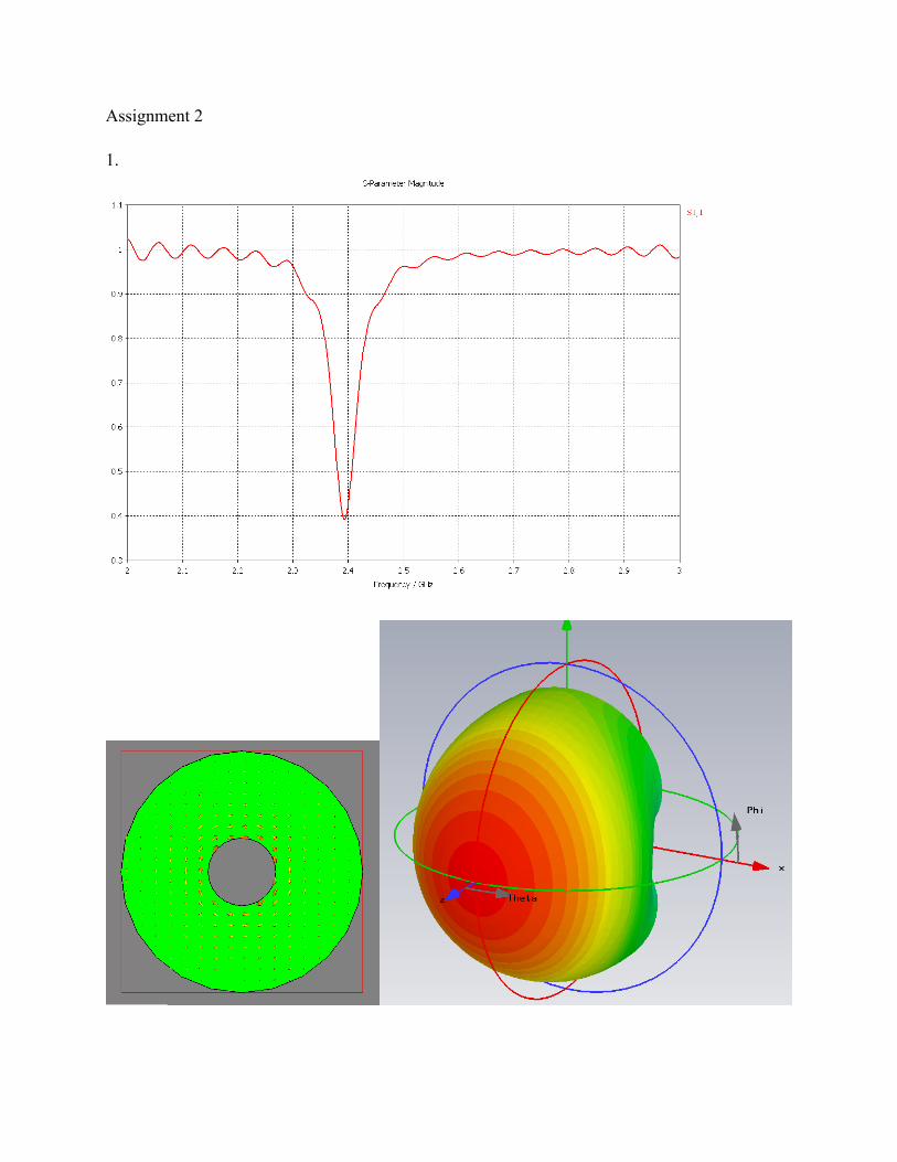
Assignment 2
1.

2. The electric field isE = (x + jy)E1e
− jkz + (x + jy) ′E1ejkz
To find the magnetic field we use Maxwell’s equation
∇ × E = − jωB = − jωµH
For individual plane waves with spatial dependence, e− jk⋅r , this can be written
− jk × E = − jωµHSolving for the magnetic field
H =1ωµk × E
The wave vectors for the incident and reflected waves are
k = ±kzand the magnetic field is then
H =1ωµ
kz × (x + jy)E1e− jkz + −kz( ) × (x + jy) ′E1e
jkz⎡⎣ ⎤⎦
Doing the cross products
H =kωµ
(y − jx)E1e− jkz − (y − jx) ′E1e
jkz⎡⎣ ⎤⎦
factoring and noting that, c =ω / k = 1 / εµ and η = µ / ε , we obtain
H =1η(y − jx) E1e
− jkz − ′E1ejkz( )
Now compute the harmonic Poynting vector or time average power, assuming k, µ and ε are real, (i.e. the medium is lossless and the waves are not evanescent waves).
Pav =12Re E ×H*( ) = 12 Re (x + jy) E1e
− jkz + ′E1ejkz( ) × 1
η(y + jx) E*1e
jkz − ′E *1e
− jkz( )⎡
⎣⎢
⎤
⎦⎥
The cross product is(x + jy) × (y + jx) = z − −z( ) = 2z
so we obtain

Pav = z1ηRe E1e
− jkz + ′E1ejkz( ) E*1e jkz − ′E *
1e− jkz( )⎡⎣ ⎤⎦
Expanding the product
Pav = z1ηRe E1
2 − ′E12 + ′E1E
*1e
j2kz − E1 ′E *1e
− j2kz( )⎡⎣
⎤⎦
The last two terms are the difference of a complex number and its conjugate which is strictly imaginary and has no real part, and the final answer is
Pav = z1η
E12 − ′E1
2( )
For the alternative reflected wave we obtain the same result
E = (x + jy)E1e− jkz + (x − jy) ′E1e
jkz
H =1ωµ
kz × (x + jy)E1e− jkz + −kz( ) × (x − jy) ′E1e
jkz⎡⎣ ⎤⎦
H =1η(y − jx)E1e
− jkz − (y + jx) ′E1ejkz⎡⎣ ⎤⎦
Pav =12Re (x + jy)E1e
− jkz + (x − jy) ′E1ejkz⎡⎣ ⎤⎦ ×
1η(y + jx)E*1e
jkz − (y − jx) ′E *1e
− jkz⎡⎣ ⎤⎦⎡
⎣⎢
⎤
⎦⎥
(x + jy) × (y + jx) = z + z(x − jy) × (y − jx) = z + z(x + jy) × (y − jx) = z − z = 0(x − jy) × (y + jx) = z − z = 0
Pav =121ηRe 2z E1
2 − 2z ′E12( )⎡
⎣⎤⎦
Pav = z1η
E12 − ′E1
2( )In both cases the incident and reflected waves were independent and no cross terms appear in the average power flow.
In the first case the reflection coefficient is the same in the x and y directions.
ρx = ρy =′E1
E1=ZL −ηZL +η
The limiting cases are
limZL→∞
′E1E1
= 1⇒ ′E1 = E1
limZL→0
′E1E1
= −1⇒ ′E1 = −E1
In the second case the reflection coefficients are different in the x and y directions.
ρx =′E1
E1
=ZLx −ηZLx +η
and ρy = − ′E1
E1
=ZLy −ηZLy +η
This can occur for the limiting cases
limZLx→∞ZLy→0
′E1E1
= 1⇒ ′E1 = E1
limZLx→0ZLy→∞
′E1E1
= −1⇒ ′E1 = −E1
3. This is a standard impedance transformation problem except that the material properties are complex and thus the wave vector will also be complex. One must be careful when using the square root function of complex numbers to choose the root for which the real part of the impedance is positive and the imaginary part of the wave vector is negative. A negative real part of impedance represents an active gain medium and a positive imaginary part of the wave vector corresponds to a wave that grows in amplitude as it propogates, neither are permitted when we assume a passive medium. Computational tools will choose a particular root of the square root function according to their own rules. Also note that in RWV,ε = ′ε − j ′′ε . (I don’t
know if that is standard in engineering books.) In this case
ηη0
=µ / µ0
ε / ε0
=1
4 − 0.04 j= 0.5000 + 0.0025j
and
k = ωv=ωc
εε0
µµ0
=2π × 3×109
2.997925 ×10¹⁰ 4 − 0.04 j = 1.2575 - 0.0063j cm−1
The impedance transformation forumula is
Zi = ηZL coskl + jηsin klηcoskl + jZL sin kl
In this case ZL is zero so
Zi = ηjηsin klηcoskl
= jη tan kl
Plugging in the numbers we note that the real part of kl is close to π/2 so the resulting impedance will be large and very sensitive to rounding of intermediate results and the precise value chosen for c.
ε = 4 − 0.04 j ⇒ Zi = 24 - 3 j kΩε = 4 ⇒ Zi = -173 j kΩ
4. We want to eliminate θ1 and θ2, replacing them with δ. For TE polarization
Zz1 = η1 secθ1 = η11
cos π2− δ⎛
⎝⎜⎞⎠⎟= η1
1sinδ
With µ1 = µ2 = µ0 we have ηi = 1/ni
Zz1 =1
n1 sinδ
We can use Snell’s law to eliminate θ2
n1 sinθ1 = n1 sinπ2− δ⎛
⎝⎜⎞⎠⎟= n1 cosδ = n2 sinθ2
sinθ2 =n1n2cosδ
The impedence in the second medium is, using a trig identity and substituting from above
Zz2 = η2 secθ2 = η21
1− sin2θ2=
1
n2 1− n1n2
⎛⎝⎜
⎞⎠⎟
2
cos2 δ
Plugging the impedence expressions into the reflection coefficient formula and defining n = n2/n1
ρ =Zz2 − Zz1
Zz2 + Zz1
=1 / Zz1 −1 / Zz2
1 / Zz1 +1 / Zz2
=n1 sinδ − n2 1− n1
n2
⎛⎝⎜
⎞⎠⎟
2
cos2 δ
n1 sinδ + n2 1− n1
n2
⎛⎝⎜
⎞⎠⎟
2
cos2 δ
=sinδ − n2 − cos2 δsinδ + n2 − cos2 δ
Finding the series expansion to first order in δ (for small δ) and noting that τ = 1 + ρ
ρ ≈ −1+ 2n2 −1
δ and τ ≈2n2 −1
δ

Similarly for TM polarization
Zz1 = η1 cosθ1 =1n1
sinδ
Zz2 = η2 cosθ2 =1n2
1− n1
n2
⎛⎝⎜
⎞⎠⎟
2
cos2 δ
ρ =n2 − cos2 δ − n2 sinδn2 − cos2 δ + n2 sinδ
ρ ≈ 1− 2n2
n2 −1δ and τ ≈ 2 −
2n2
n2 −1δ
5. At the half-power angle, θh, the raditation intensity is half its maximum, which occurs at θ = 0.
U θh( ) = cosnθh =12cosn 0 = 1
2Take the log of both sides
n ln cosθh( ) = − ln2
Solve for n
n = −ln2
ln cosθh( )Since the HPBW (Half Power Beam Width) is defined as the full included angle for half power, we take half of that, or 5 degrees, for θh. Plugging in we find n.
θh =
102
π180 0.0872665 ⇒ n = 181.81
To find the directivity, first we find the radiated power for our intensity function, U.
Prad = U θ( )sinθ dθ dφ0
π
∫0
2π
∫Since the radiation intensity is independent of the azimuthal angle, ϕ, we can immediately do the ϕ integral.
Prad = 2π U θ( )sinθ dθ0
π
∫
Inserting our raditaion intensity, which is zero for θ > π/2, we can do the integral by substitution and find the radiated power.
Prad = 2π cosnθ sinθ dθ0
π /2
∫ = −2π un du1
0
∫ = 2π un+1
n +1⎡
⎣⎢
⎤
⎦⎥0
1
=2πn +1
The directivity is then
D θ( ) = U θ( )Prad / 4π
= 2 n +1( )cosnθ
and it’s maximum is given by
Dmax = 2 n +1( ) 365.61
6. Write the electric field with an unknown coefficient (for solving part b)
E =E0 0 ≤θ ≤ π / 40 π / 4 < θ < π / 2
E0 / 2 π / 2 ≤θ ≤ π
⎧
⎨⎪
⎩⎪
The radiation intensity is given by
U =r2
2ηE 2 =
r2
2ηE0
21 0 ≤θ ≤ π / 40 π / 4 < θ < π / 21 / 4 π / 2 ≤θ ≤ π
⎧⎨⎪
⎩⎪
and the radiated power is
Prad = 2π U θ( )sinθ dθ0
π
∫ = 2π r2
2ηE0
2 sinθ dθ0
π /4
∫ +14
sinθ dθπ /2
π
∫⎡
⎣⎢
⎤
⎦⎥
Doing the integral, we find
Prad = 2πr2
2ηE0
2 − cosθ[ ]0π /4 +
14
− cosθ[ ]π /2π⎡
⎣⎢⎤⎦⎥= 2π r2
2ηE0
2 −12+1⎛
⎝⎜⎞⎠⎟+141− 0( )⎡
⎣⎢
⎤
⎦⎥ = α r2
2ηE0
2
where
α = 2π 54−12
⎡⎣⎢
⎤⎦⎥≈ 3.4111
The directivity is then
D θ( ) = U θ( )Prad / 4π
=4πα
1 0 ≤θ ≤ π / 40 π / 4 < θ < π / 2
1 / 4 π / 2 ≤θ ≤ π
⎧⎨⎪
⎩⎪ where 4π
α≈ 3.684
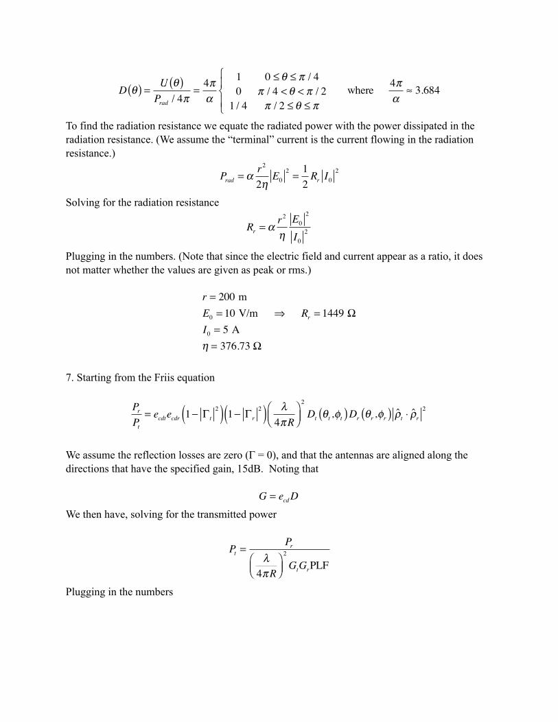
To find the radiation resistance we equate the radiated power with the power dissipated in the radiation resistance. (We assume the “terminal” current is the current flowing in the radiation resistance.)
Prad = αr2
2ηE0
2 =12Rr I0
2
Solving for the radiation resistance
Rr = αr2
ηE0
2
I02
Plugging in the numbers. (Note that since the electric field and current appear as a ratio, it does not matter whether the values are given as peak or rms.)
r = 200 mE0 = 10 V/m ⇒ Rr = 1449 ΩI0 = 5 Aη = 376.73 Ω
7. Starting from the Friis equation
PrPt
= ecdtecdr 1− Γ t2( ) 1− Γ r
2( ) λ4πR
⎛⎝⎜
⎞⎠⎟2
Dt θt ,φt( )Dr θr ,φr( ) ρt ⋅ ρr 2
We assume the reflection losses are zero (Γ = 0), and that the antennas are aligned along the directions that have the specified gain, 15dB. Noting that
G = ecdDWe then have, solving for the transmitted power
Pt =Pr
λ4πR
⎛⎝⎜
⎞⎠⎟2
GtGrPLF
Plugging in the numbers

Pr = 10 ×10−9 Wλ = c / f = 0.03 mR = 10 ×103 m ⇒ Pt = 350 WGt = Gr = 15 dB = 101.5
PLF = −3 dB = 10−0.3


![Contentshomepages.math.uic.edu/~coskun/rigidorth.pdf · 2016. 3. 5. · been investigated by many authors for the Grassmannian G(k;n) (see [HRT], [K1], [KL] and [C1]). We will say](https://static.fdocument.org/doc/165x107/60e542f22c7b2556ef48d23a/coskunrigidorthpdf-2016-3-5-been-investigated-by-many-authors-for-the-grassmannian.jpg)