ANALYSIS AND APPLICATION OF SUITABLE CFD...
20
European Congress on Computational Methods in Applied Sciences and Engineering (ECCOMAS 2012) J. Eberhardsteiner et.al. (eds.) Vienna, Austria, September 10-14, 2012 ANALYSIS AND APPLICATION OF SUITABLE CFD-BASED OPTIMIZATION STRATEGIES FOR HIGH-LIFT SYSTEM DESIGN Pierluigi Iannelli 1 , Jochen Wild 2 , Mauro Minervino 3,1 , Frederic Moens 4 and Michael Raets 5 1 CIRA - Italian Aerospace Research Centre, Aircrafts/Fluid Mechanics Unit, Fluid Dynamics Lab. Via Maiorise, Capua, 81043, Italy e-mail: [email protected] - [email protected] 2 DLR - German Aerospace Research Centre, Institute of Aerodynamics and Flow Technology Lilienthalplatz 7, Braunschweig, 38108, Germany e-mail: [email protected] 3 Piaggio Aero Industries S.p.A., P.H.T. - Piaggio High Technology Department Via Campi Flegrei 34, Pozzuoli, 80078, Italy 4 ONERA - The French Aerospace Lab., Applied Aerodynamics Department, Civil Aircraft Unit Rue des Vertugadins 8, Meudon, 92190, France e-mail: [email protected] 5 ASCO Industries N.V. – Engineering Department Weiveldlaan 2, Zaventem, 1930, Belgium e-mail: [email protected] Keywords: high-lift, design, optimization, natural laminar flow, multidisciplinary Abstract. The design of high-lift (HL) systems represents a challenging task within the aero- space community, due to its multidisciplinary, multi-objective and multi-point nature. Within the paper an additional difficulty is considered, consisting in the design of a HL system for a High Aspect Ratio Low Sweep (HARLS) wing, featuring Natural Laminar Flow (NLF) at transonic cruise conditions. In a first “analysis” phase a realistic optimization problem is defined and solved by adopting different approaches in terms of employed flow model, mesh- ing strategies, geometry parameterization and optimization strategies. In a second “applica- tion” phase, the design of an optimal feasible HL system is developed for the HARLS-NLF wing, by considering a close coupling between 3D CFD-based optimization, kinematical lay- out studies and mechanical integration studies.
Transcript of ANALYSIS AND APPLICATION OF SUITABLE CFD...
European Congress on Computational Methods
in Applied Sciences and Engineering (ECCOMAS 2012)
J. Eberhardsteiner et.al. (eds.)
Vienna, Austria, September 10-14, 2012
ANALYSIS AND APPLICATION OF SUITABLE CFD-BASED
OPTIMIZATION STRATEGIES FOR HIGH-LIFT SYSTEM DESIGN
Pierluigi Iannelli1, Jochen Wild
2, Mauro Minervino
3,1, Frederic Moens
4 and Michael
Raets5
1 CIRA - Italian Aerospace Research Centre, Aircrafts/Fluid Mechanics Unit, Fluid Dynamics Lab.
Via Maiorise, Capua, 81043, Italy e-mail: [email protected] - [email protected]
2 DLR - German Aerospace Research Centre, Institute of Aerodynamics and Flow Technology
Lilienthalplatz 7, Braunschweig, 38108, Germany e-mail: [email protected]
3 Piaggio Aero Industries S.p.A., P.H.T. - Piaggio High Technology Department
Via Campi Flegrei 34, Pozzuoli, 80078, Italy
4 ONERA - The French Aerospace Lab., Applied Aerodynamics Department, Civil Aircraft Unit
Rue des Vertugadins 8, Meudon, 92190, France
e-mail: [email protected]
5 ASCO Industries N.V. – Engineering Department
Weiveldlaan 2, Zaventem, 1930, Belgium
e-mail: [email protected]
Keywords: high-lift, design, optimization, natural laminar flow, multidisciplinary
Abstract. The design of high-lift (HL) systems represents a challenging task within the aero-
space community, due to its multidisciplinary, multi-objective and multi-point nature. Within
the paper an additional difficulty is considered, consisting in the design of a HL system for a
High Aspect Ratio Low Sweep (HARLS) wing, featuring Natural Laminar Flow (NLF) at
transonic cruise conditions. In a first “analysis” phase a realistic optimization problem is
defined and solved by adopting different approaches in terms of employed flow model, mesh-
ing strategies, geometry parameterization and optimization strategies. In a second “applica-
tion” phase, the design of an optimal feasible HL system is developed for the HARLS-NLF
wing, by considering a close coupling between 3D CFD-based optimization, kinematical lay-
out studies and mechanical integration studies.
Pierluigi Iannelli, Jochen Wild, Mauro Minervino, Frederic Moens and Michael Raets
2
1 INTRODUCTION
As well known, the design and optimization of High-Lift (HL) systems represents a chal-
lenging task for aircraft manufacturers, due to its multidisciplinary, multi-objective and multi-
point nature. The design of HL devices typically involves the improvement of performances
related to different flight phases, e.g. Take-Off (TO) and Landing (LDG). Normally, in each
flight phase several performance indexes are to be improved or controlled at different flight
conditions, and airworthiness requirements additionally pose both important boundaries to the
design space and complicate the optimization problem formulation. Moreover, manufacturing
constraints must be respected, as the designed shape must ensure enough structural stiffness to
maintain the high aerodynamic loads occurring whereas, the external shape of the retracted
wing must be compliant with the designated cruise clean wing shape. Finally, during the de-
sign phase the mechanical integration and kinematical reliability must be accounted for, in
order to avoid unrealistic aerodynamic designs. All these features make the task of designing
a HL system particularly difficult and often translate into stiff scenarios.
The DeSiReH project (Design, Simulation and Flight Reynolds Number testing for ad-
vanced High Lift Solutions) [1], funded by the European Commission in the 7th Framework
Program, aims at improving the aerodynamics of HL systems by considering, in a coordinated
approach, the development of both efficient numerical design strategies and measurement
techniques for cryogenic wind tunnel conditions. It represents the follow up to the
EUROLIFT I and II projects, wherein both numerical and experimental studies were mainly
targeted towards validation of CFD tools for maximum lift prediction of increasingly com-
plexity configurations up to flight Reynolds numbers. The target application of the DeSiReH
project is the design of a realistic HL system for a High Aspect Ratio Low Sweep (HARLS)
wing, featuring Natural Laminar Flow (NLF) at transonic cruise conditions.
Within this paper, an overview is given of the CFD-based optimization activities carried
out in two phases of the DeSiReH project. In a first “analysis” phase (i.e., Task 1.2), a realis-
tic multi-objective/multi-point optimization problem is defined and solved by a group of part-
ners adopting different approaches in terms of employed flow model, meshing techniques,
geometry parameterization and optimization strategies. The results obtained are compared and
efficiencies/deficiencies of the adopted approaches are highlighted. The experience gained in
the first phase of the project is exploited in a second “application” phase (i.e., Task 2.1),
wherein the design of an optimal feasible HL system is developed for a HARLS-NLF wing.
In this phase the design work is first concentrated on the 2D assessment of several candidate
concepts, by considering CFD-based 2D optimization targeting lift maximization. At the same
time, mechanical integration aspects are gradually developed and integrated into the explored
HL concepts, leading afterwards to a refined constrained optimization of the 2D concepts.
Based on 2D performance comparisons and integration aspects, the most promising concepts
are down selected and a detailed 3D numerical optimization is carried out afterwards, for se-
lected leading edge and trailing edge concepts. In this 3D phase the matured mechanical and
structural constraint directives are included in the optimization loop. The solution of the 3D
HL optimization problem is detailed and the final results obtained are described within the
paper.
2 ANALYSIS OF HIGH-LIFT DESIGN STRATEGIES
Within the DeSiReH project, the work package 1 (WP1) is specifically dedicated to the
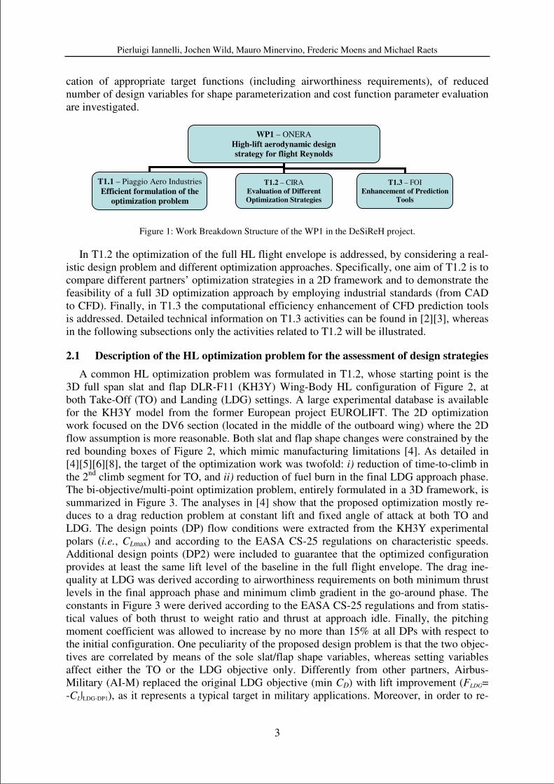
analysis and improvement of HL aerodynamic design strategies. In Figure 1 it is shown the
WP1 structure wherein Task 1.1 (T1.1) aims at defining efficient formulations of the HL op-
timization problem as a first step towards a reduction of design cycle time. Therein, identifi-
Pierluigi Iannelli, Jochen Wild, Mauro Minervino, Frederic Moens and Michael Raets
3
cation of appropriate target functions (including airworthiness requirements), of reduced
number of design variables for shape parameterization and cost function parameter evaluation
are investigated.
Figure 1: Work Breakdown Structure of the WP1 in the DeSiReH project.
In T1.2 the optimization of the full HL flight envelope is addressed, by considering a real-
istic design problem and different optimization approaches. Specifically, one aim of T1.2 is to
compare different partners’ optimization strategies in a 2D framework and to demonstrate the
feasibility of a full 3D optimization approach by employing industrial standards (from CAD
to CFD). Finally, in T1.3 the computational efficiency enhancement of CFD prediction tools
is addressed. Detailed technical information on T1.3 activities can be found in [2][3], whereas
in the following subsections only the activities related to T1.2 will be illustrated.
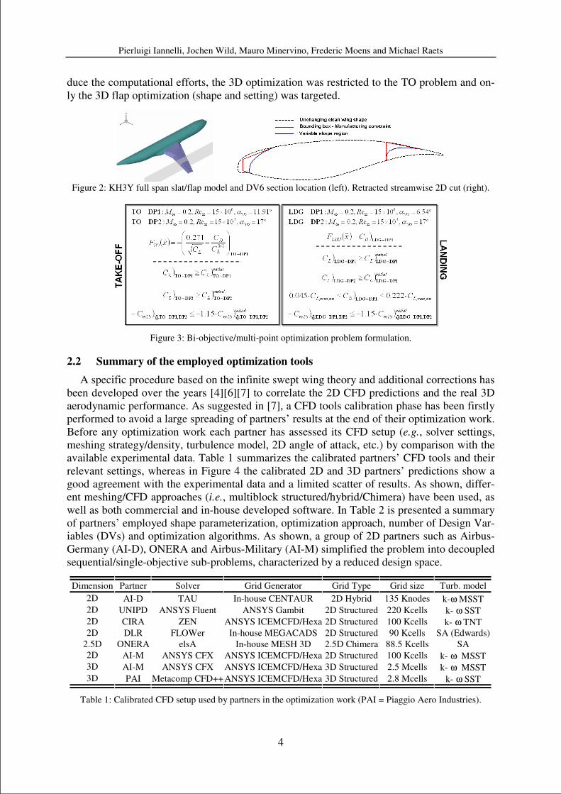
2.1 Description of the HL optimization problem for the assessment of design strategies
A common HL optimization problem was formulated in T1.2, whose starting point is the
3D full span slat and flap DLR-F11 (KH3Y) Wing-Body HL configuration of Figure 2, at
both Take-Off (TO) and Landing (LDG) settings. A large experimental database is available
for the KH3Y model from the former European project EUROLIFT. The 2D optimization
work focused on the DV6 section (located in the middle of the outboard wing) where the 2D
flow assumption is more reasonable. Both slat and flap shape changes were constrained by the
red bounding boxes of Figure 2, which mimic manufacturing limitations [4]. As detailed in
[4][5][6][8], the target of the optimization work was twofold: i) reduction of time-to-climb in
the 2nd
climb segment for TO, and ii) reduction of fuel burn in the final LDG approach phase.
The bi-objective/multi-point optimization problem, entirely formulated in a 3D framework, is
summarized in Figure 3. The analyses in [4] show that the proposed optimization mostly re-
duces to a drag reduction problem at constant lift and fixed angle of attack at both TO and
LDG. The design points (DP) flow conditions were extracted from the KH3Y experimental
polars (i.e., CLmax) and according to the EASA CS-25 regulations on characteristic speeds.
Additional design points (DP2) were included to guarantee that the optimized configuration
provides at least the same lift level of the baseline in the full flight envelope. The drag ine-
quality at LDG was derived according to airworthiness requirements on both minimum thrust
levels in the final approach phase and minimum climb gradient in the go-around phase. The
constants in Figure 3 were derived according to the EASA CS-25 regulations and from statis-
tical values of both thrust to weight ratio and thrust at approach idle. Finally, the pitching
moment coefficient was allowed to increase by no more than 15% at all DPs with respect to
the initial configuration. One peculiarity of the proposed design problem is that the two objec-
tives are correlated by means of the sole slat/flap shape variables, whereas setting variables
affect either the TO or the LDG objective only. Differently from other partners, Airbus-
Military (AI-M) replaced the original LDG objective (min CD) with lift improvement (FLDG=
-CL|LDG-DP1), as it represents a typical target in military applications. Moreover, in order to re-
WP1 – ONERA
High-lift aerodynamic design
strategy for flight Reynolds
T1.1 – Piaggio Aero Industries
Efficient formulation of the
optimization problem
T1.2 – CIRA
Evaluation of Different
Optimization Strategies
T1.3 – FOI
Enhancement of Prediction
Tools
Pierluigi Iannelli, Jochen Wild, Mauro Minervino, Frederic Moens and Michael Raets
4
duce the computational efforts, the 3D optimization was restricted to the TO problem and on-
ly the 3D flap optimization (shape and setting) was targeted.
Figure 2: KH3Y full span slat/flap model and DV6 section location (left). Retracted streamwise 2D cut (right).
Figure 3: Bi-objective/multi-point optimization problem formulation.
2.2 Summary of the employed optimization tools
A specific procedure based on the infinite swept wing theory and additional corrections has
been developed over the years [4][6][7] to correlate the 2D CFD predictions and the real 3D
aerodynamic performance. As suggested in [7], a CFD tools calibration phase has been firstly
performed to avoid a large spreading of partners’ results at the end of their optimization work.
Before any optimization work each partner has assessed its CFD setup (e.g., solver settings,
meshing strategy/density, turbulence model, 2D angle of attack, etc.) by comparison with the
available experimental data. Table 1 summarizes the calibrated partners’ CFD tools and their
relevant settings, whereas in Figure 4 the calibrated 2D and 3D partners’ predictions show a
good agreement with the experimental data and a limited scatter of results. As shown, differ-
ent meshing/CFD approaches (i.e., multiblock structured/hybrid/Chimera) have been used, as
well as both commercial and in-house developed software. In Table 2 is presented a summary
of partners’ employed shape parameterization, optimization approach, number of Design Var-
iables (DVs) and optimization algorithms. As shown, a group of 2D partners such as Airbus-
Germany (AI-D), ONERA and Airbus-Military (AI-M) simplified the problem into decoupled
sequential/single-objective sub-problems, characterized by a reduced design space.
Dimension Partner Solver Grid Generator Grid Type Grid size Turb. model
2D AI-D TAU In-house CENTAUR 2D Hybrid 135 Knodes k-ω MSST
2D UNIPD ANSYS Fluent ANSYS Gambit 2D Structured 220 Kcells k- ω SST
2D CIRA ZEN ANSYS ICEMCFD/Hexa 2D Structured 100 Kcells k- ω TNT
2D DLR FLOWer In-house MEGACADS 2D Structured 90 Kcells SA (Edwards)
2.5D ONERA elsA In-house MESH 3D 2.5D Chimera 88.5 Kcells SA
2D AI-M ANSYS CFX ANSYS ICEMCFD/Hexa 2D Structured 100 Kcells k- ω MSST
3D AI-M ANSYS CFX ANSYS ICEMCFD/Hexa 3D Structured 2.5 Mcells k- ω MSST
3D PAI Metacomp CFD++ ANSYS ICEMCFD/Hexa 3D Structured 2.8 Mcells k- ω SST
Table 1: Calibrated CFD setup used by partners in the optimization work (PAI = Piaggio Aero Industries).
Pierluigi Iannelli, Jochen Wild, Mauro Minervino, Frederic Moens and Michael Raets
5
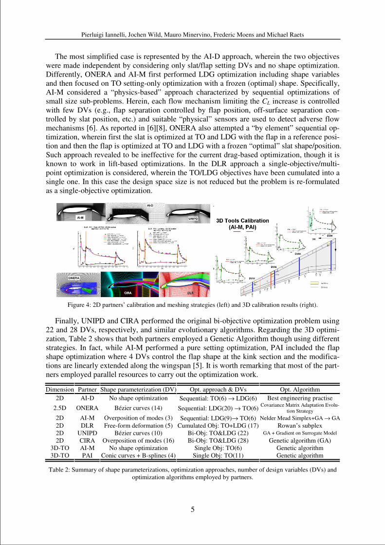
The most simplified case is represented by the AI-D approach, wherein the two objectives
were made independent by considering only slat/flap setting DVs and no shape optimization.
Differently, ONERA and AI-M first performed LDG optimization including shape variables
and then focused on TO setting-only optimization with a frozen (optimal) shape. Specifically,
AI-M considered a “physics-based” approach characterized by sequential optimizations of
small size sub-problems. Herein, each flow mechanism limiting the CL increase is controlled
with few DVs (e.g., flap separation controlled by flap position, off-surface separation con-
trolled by slat position, etc.) and suitable “physical” sensors are used to detect adverse flow
mechanisms [6]. As reported in [6][8], ONERA also attempted a “by element” sequential op-
timization, wherein first the slat is optimized at TO and LDG with the flap in a reference posi-
tion and then the flap is optimized at TO and LDG with a frozen “optimal” slat shape/position.
Such approach revealed to be ineffective for the current drag-based optimization, though it is
known to work in lift-based optimizations. In the DLR approach a single-objective/multi-
point optimization is considered, wherein the TO/LDG objectives have been cumulated into a
single one. In this case the design space size is not reduced but the problem is re-formulated
as a single-objective optimization.
Figure 4: 2D partners’ calibration and meshing strategies (left) and 3D calibration results (right).
Finally, UNIPD and CIRA performed the original bi-objective optimization problem using
22 and 28 DVs, respectively, and similar evolutionary algorithms. Regarding the 3D optimi-
zation, Table 2 shows that both partners employed a Genetic Algorithm though using different
strategies. In fact, while AI-M performed a pure setting optimization, PAI included the flap
shape optimization where 4 DVs control the flap shape at the kink section and the modifica-
tions are linearly extended along the wingspan [5]. It is worth remarking that most of the part-
ners employed parallel resources to carry out the optimization work.
Dimension Partner Shape parameterization (DV) Opt. approach & DVs Opt. Algorithm
2D AI-D No shape optimization Sequential: TO(6) → LDG(6) Best engineering practise
2.5D ONERA Bézier curves (14) Sequential: LDG(20) → TO(6) Covariance Matrix Adaptation Evolu-
tion Strategy
2D AI-M Overposition of modes (3) Sequential: LDG(9)→ TO(6) Nelder Mead Simplex+GA → GA
2D DLR Free-form deformation (5) Cumulated Obj: TO+LDG (17) Rowan’s subplex
2D UNIPD Bézier curves (10) Bi-Obj: TO&LDG (22) GA + Gradient on Surrogate Model
2D CIRA Overposition of modes (16) Bi-Obj: TO&LDG (28) Genetic algorithm (GA)
3D-TO AI-M No shape optimization Single Obj: TO(6) Genetic algorithm
3D-TO PAI Conic curves + B-splines (4) Single Obj: TO(11) Genetic algorithm
Table 2: Summary of shape parameterizations, optimization approaches, number of design variables (DVs) and
optimization algorithms employed by partners.
Pierluigi Iannelli, Jochen Wild, Mauro Minervino, Frederic Moens and Michael Raets
6
2.3 Optimization results
A detailed analysis of optimization results is given in [6] and only the major outcomes will
be summarized herein. Three “evaluators” have been appointed (AI-D/ONERA/UNIPD), hav-
ing the role of re-evaluating all 2D optimized geometries to verify the declared partners’ per-
formance improvements. According to the considered drag-reduction problem a careful
treatment of different lift levels was needed to avoid mystifications of the real improvements
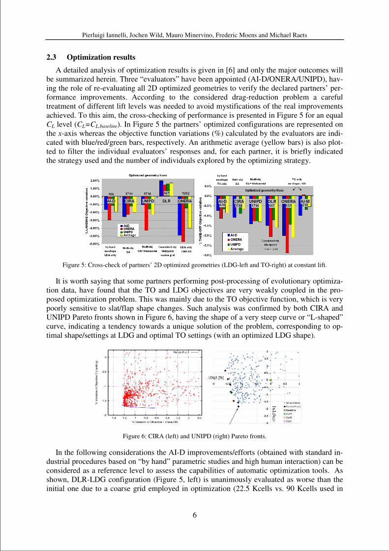
achieved. To this aim, the cross-checking of performance is presented in Figure 5 for an equal
CL level (CL=CL,baseline). In Figure 5 the partners’ optimized configurations are represented on
the x-axis whereas the objective function variations (%) calculated by the evaluators are indi-
cated with blue/red/green bars, respectively. An arithmetic average (yellow bars) is also plot-
ted to filter the individual evaluators’ responses and, for each partner, it is briefly indicated
the strategy used and the number of individuals explored by the optimizing strategy.
Figure 5: Cross-check of partners’ 2D optimized geometries (LDG-left and TO-right) at constant lift.
It is worth saying that some partners performing post-processing of evolutionary optimiza-
tion data, have found that the TO and LDG objectives are very weakly coupled in the pro-
posed optimization problem. This was mainly due to the TO objective function, which is very
poorly sensitive to slat/flap shape changes. Such analysis was confirmed by both CIRA and
UNIPD Pareto fronts shown in Figure 6, having the shape of a very steep curve or “L-shaped”
curve, indicating a tendency towards a unique solution of the problem, corresponding to op-
timal shape/settings at LDG and optimal TO settings (with an optimized LDG shape).
Figure 6: CIRA (left) and UNIPD (right) Pareto fronts.
In the following considerations the AI-D improvements/efforts (obtained with standard in-
dustrial procedures based on “by hand” parametric studies and high human interaction) can be
considered as a reference level to assess the capabilities of automatic optimization tools. As
shown, DLR-LDG configuration (Figure 5, left) is unanimously evaluated as worse than the
initial one due to a coarse grid employed in optimization (22.5 Kcells vs. 90 Kcells used in
Pierluigi Iannelli, Jochen Wild, Mauro Minervino, Frederic Moens and Michael Raets
7
calibration). Such mesh density, thought inadequate for LDG optimization, was successfully
employed at TO (Figure 5, right) where the DLR configuration improvement is 1.5% on aver-
age. CIRA and UNIPD obtained similar improvements using comparable approaches (bi-
objective GA-based opt., large number of DVs). Specifically, UNIPD strategy shows slightly
better performance over CIRA, likely due to the employed local search, gradient-based algo-
rithm working on the Neural-Network Metamodel, which enhanced the global GA evolution
rate. While CIRA/UNIPD results show little differences at LDG compared to AI-D, UNIPD
improvements at TO are doubled compared to AI-D. On the other hand, ONERA worked with
a reduced design space (especially at LDG) due to the applied decoupling and employed an
(advanced) evolutionary approach as CIRA/UNIPD. Thanks to the reduced problem(s) size,
the design space was more widely explored in each of the single-objective optimizations per-
formed, thus providing larger improvements. This likely explains the best performance ob-
tained by ONERA for both objectives considered. It is worth noting that direct comparison of
AI-D vs. ONERA results at LDG show potentials of automatic optimization capabilities. Fi-
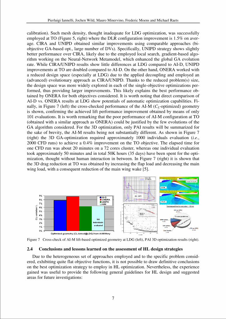
nally, in Figure 7 (left) the cross-checked performance of the AI-M (CL-optimized) geometry
is shown, confirming the achieved lift performance improvement obtained by means of only
101 evaluations. It is worth remarking that the poor performance of AI-M configuration at TO
(obtained with a similar approach as ONERA) could be justified by the few evolutions of the
GA algorithm considered. For the 3D optimization, only PAI results will be summarized for
the sake of brevity, the AI-M results being not substantially different. As shown in Figure 7
(right) the 3D GA-optimization required approximately 1000 individuals evaluation (i.e.,
2000 CFD runs) to achieve a 0.4% improvement on the TO objective. The elapsed time for
one CFD run was about 20 minutes on a 72 cores cluster, whereas one individual evaluation
took approximately 50 minutes and in total 50K hours (35 days) have been spent for the opti-
mization, thought without human interaction in between. In Figure 7 (right) it is shown that
the 3D drag reduction at TO was obtained by increasing the flap load and decreasing the main
wing load, with a consequent reduction of the main wing wake [5].
Figure 7 Cross-check of AI-M lift-based optimized geometry at LDG (left), PAI 3D optimization results (right).
2.4 Conclusions and lessons learned on the assessment of HL design strategies
Due to the heterogeneous set of approaches employed and to the specific problem consid-
ered, exhibiting quite flat objective functions, it is not possible to draw definitive conclusions
on the best optimization strategy to employ in HL optimization. Nevertheless, the experience
gained was useful to provide the following general guidelines for HL design and suggested
areas for future investigations:
Pierluigi Iannelli, Jochen Wild, Mauro Minervino, Frederic Moens and Michael Raets
8
• For the same decoupled approach, the automatic ONERA optimization provided double
improvements compared to the AI-D approach based on current industrial standards. This
indicates that the introduction in industry of automatic optimization should be more and
more pursued, as it would allow for interesting margins of performance improvements.
Nevertheless, other partners’ results have shown that automatic optimizations not always
produce clear improvements over the industrial approach. This happens especially when
the design space is not adequately explored (either because the design space is too wide or
because the optimization is stopped prematurely).
• Observation of CIRA/UNIPD/ONERA-LDG optimizations indicates that the usage of a
high number of DVs requires a large number of evolutions to achieve significant im-
provements in evolutionary approaches. In this context, comparison of CIRA vs. UNIPD
performance indicates that usage of surrogate models helps enhancing convergence. More-
over, ONERA-LDG optimization results (using a comparable number of DVs as
CIRA/UNIPD) indicate a potential superiority of the employed Covariance Matrix Adapta-
tion Evolution Strategy algorithm in comparison to classical evolutionary approaches.
• The usage of decoupling/sequential strategies (allowing a reduced design spaces) is highly
recommended. However, not all the sequential strategies are effective. As mentioned above,
the “by element” decoupling considered by ONERA resulted to be unreliable for the cur-
rent drag-based problem, whereas the “by configuration” sequence shown herein demon-
strated to be very useful. This indicates that applicability of sequential strategies must be
assessed a-priori by preliminary analyses or pre-knowledge of the optimization problem.
• AI-M (LDG) physics-driven optimization, being based on a very small number of DVs
proven to be very powerful and cost-effective. As expected, the introduction of engineering
knowledge allows efficient formulation/solution of the problem and it is always suggested
whenever possible.
• The DLR experience indicates that strategies based on approximate fitness function
evaluation (i.e., coarse grid) are to be carefully employed in HL numerical optimization
and that preliminary assessments are needed to setup a reliable strategy.
• The employment of a full automatic 3D HL optimization chain based on currently avail-
able industrial tools looks feasible nowadays. As shown, it requires large but not prohibi-
tive computational resources and based on the above 2D outcomes it could provide
interesting margins of improvements with respect to the parametric industrial approach.
• In cooperative optimization activities, in order to further reduce the scatter of partners’ im-
provements quantification (as shown in Figure 5), it is suggested to perform the CFD codes
calibration (on the initial configuration) by considering also lift and drag coefficients rather
than only matching the experimental pressure distributions as considered herein.
3 DESIGN OF A NLF-WING COMPATIBLE HIGH-LIFT SYSTEM
Based on the experience gained during the assessment of optimization strategies, these
methods are in a second step applied to a very challenging design task. The application shall
demonstrate the benefits of using optimization based design methods for real world applica-
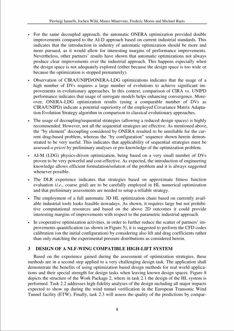
tions and their special strength for design tasks when leaving known design spaces. Figure 8
depicts the structure of the Work Package 2, where in task 2.1 the design of the HL system is
performed. Task 2.2 addresses high-fidelity analyses of the design including all major impacts
expected to show up during the wind tunnel verification in the European Transonic Wind
Tunnel facility (ETW). Finally, task 2.3 will assess the quality of the predictions by compar-
Pierluigi Iannelli, Jochen Wild, Mauro Minervino, Frederic Moens and Michael Raets
9
ing the obtained wind tunnel data with the CFD based predictions. Within the design task first
suitable concepts are identified by using the same wing section design methodology as it was
used and evaluated in the two-dimensional optimization framework reported earlier. In addi-
tion to the purely aerodynamics driven optimization method, feasibility of the designed HL
system is a major intention of the performed design work within this work package.
Figure 8: Breakdown of the work package assigned to the design of the laminar wing compatible high-lift system.
Especially, leading edge devices stored into a NLF wing pose larger difficulties due to the
relatively limited space available. In order to achieve this goal in parallel to the design work,
the concepts investigated were assessed in terms of suitable kinematics and their mechanical
integration. Conflicts arising from this view were used in refinements of the designs, espe-
cially by posing the necessary geometric constraints. Finally the complete high-lift system for
the 3D wing was designed making again use of the experience gained in the first work pack-
age concerning aerodynamic 3D high-lift system optimization.
3.1 Selection of NLF wing compatible high-lift systems
Prior to any design work, the type of HL system to be adapted to the wing has to be de-
fined. The key parameter to help for the selection is the required level of maximum lift in
landing conditions, which depends on the aircraft weight and wing area. For the current con-
figuration, the maximum lift of the clean wing configuration has to be increased at least of
∆CL,max=1.25 for landing. The use of a trailing-edge system is therefore mandatory, but a clas-
sical Fowler single slotted flap should generate sufficient lift. Even a double slotted flap or
flaps that incorporate spoiler droop seem feasible and well known solutions.
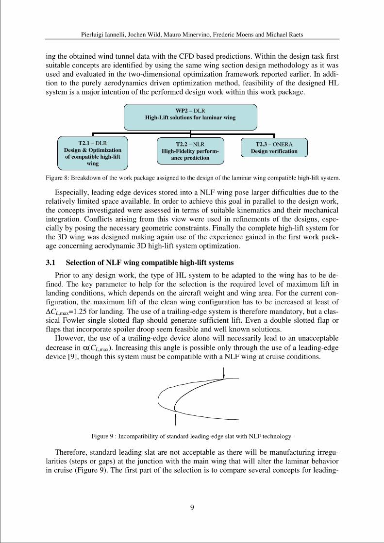
However, the use of a trailing-edge device alone will necessarily lead to an unacceptable
decrease in α(CL,max). Increasing this angle is possible only through the use of a leading-edge
device [9], though this system must be compatible with a NLF wing at cruise conditions.
Figure 9 : Incompatibility of standard leading-edge slat with NLF technology.
Therefore, standard leading slat are not acceptable as there will be manufacturing irregu-
larities (steps or gaps) at the junction with the main wing that will alter the laminar behavior
in cruise (Figure 9). The first part of the selection is to compare several concepts for leading-
WP2 – DLR
High-Lift solutions for laminar wing
T2.1 – DLR
Design & Optimization
of compatible high-lift
wing
T2.2 – NLR
High-Fidelity perform-
ance prediction
T2.3 – ONERA
Design verification
Pierluigi Iannelli, Jochen Wild, Mauro Minervino, Frederic Moens and Michael Raets
10
edge devices that are compatible with NLF technology based on aerodynamic performance
only. Then, integration aspects will be considered in the final optimization process.
3.2 Evaluation of individual leading-edge devices
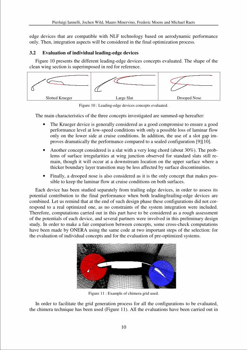
Figure 10 presents the different leading-edge devices concepts evaluated. The shape of the
clean wing section is superimposed in red for reference.
Slotted Krueger Large Slat Drooped Nose
Figure 10 : Leading-edge devices concepts evaluated.
The main characteristics of the three concepts investigated are summed-up hereafter:
• The Krueger device is generally considered as a good compromise to ensure a good
performance level at low-speed conditions with only a possible loss of laminar flow
only on the lower side at cruise conditions. In addition, the use of a slot gap im-
proves dramatically the performance compared to a sealed configuration [9][10].
• Another concept considered is a slat with a very long chord (about 30%). The prob-
lems of surface irregularities at wing junction observed for standard slats still re-
main, though it will occur at a downstream location on the upper surface where a
thicker boundary layer transition may be less affected by surface discontinuities.
• Finally, a drooped nose is also considered as it is the only concept that makes pos-
sible to keep the laminar flow at cruise conditions on both surfaces.
Each device has been studied separately from trailing edge devices, in order to assess its
potential contribution to the final performance when both leading/trailing-edge devices are
combined. Let us remind that at the end of such design phase these configurations did not cor-
respond to a real optimized one, as no constraints of the system integration were included.
Therefore, computations carried out in this part have to be considered as a rough assessment
of the potentials of each device, and several partners were involved in this preliminary design
study. In order to make a fair comparison between concepts, some cross-check computations
have been made by ONERA using the same code at two important steps of the selection: for
the evaluation of individual concepts and for the evaluation of pre-optimized systems.
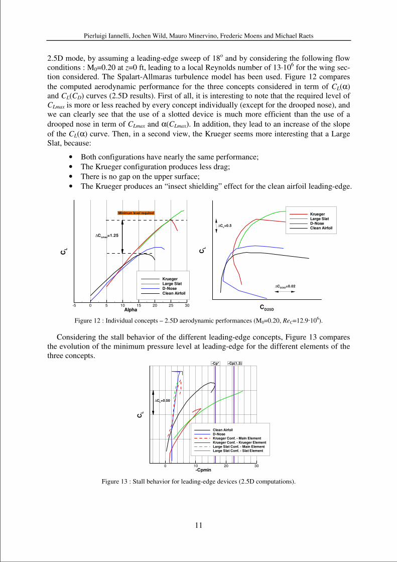
Figure 11 : Example of chimera grid used.
In order to facilitate the grid generation process for all the configurations to be evaluated,
the chimera technique has been used (Figure 11). All the evaluations have been carried out in
Pierluigi Iannelli, Jochen Wild, Mauro Minervino, Frederic Moens and Michael Raets
11
2.5D mode, by assuming a leading-edge sweep of 18o and by considering the following flow
conditions : M0=0.20 at z=0 ft, leading to a local Reynolds number of 13·106 for the wing sec-
tion considered. The Spalart-Allmaras turbulence model has been used. Figure 12 compares
the computed aerodynamic performance for the three concepts considered in term of CL(α)
and CL(CD) curves (2.5D results). First of all, it is interesting to note that the required level of
CLmax is more or less reached by every concept individually (except for the drooped nose), and
we can clearly see that the use of a slotted device is much more efficient than the use of a
drooped nose in term of CLmax and α(CLmax). In addition, they lead to an increase of the slope
of the CL(α) curve. Then, in a second view, the Krueger seems more interesting that a Large
Slat, because:
• Both configurations have nearly the same performance;
• The Krueger configuration produces less drag;
• There is no gap on the upper surface;
• The Krueger produces an “insect shielding” effect for the clean airfoil leading-edge.
Alpha
CL
-5 0 5 10 15 20 25 30
KruegerLarge Slat
D-Nose
Clean Airfoil
Minimum level required
∆CLmax
=1.25
CD25D
CL
Krueger
Large Slat
D-NoseClean Airfoil
∆CL=0.5
∆CD25D
=0.02
Figure 12 : Individual concepts – 2.5D aerodynamic performances (M0=0.20, ReC=12.9·106).
Considering the stall behavior of the different leading-edge concepts, Figure 13 compares
the evolution of the minimum pressure level at leading-edge for the different elements of the
three concepts.
-Cpmin
CL
0 10 20 30
Clean Airfoil
D-Nose
Krueger Conf. - Main Element
Krueger Conf. - Krueger Element
Large Slat Conf. - Main ElementLarge Slat Conf. - Slat Element
-Cp(1.3)-Cp*
∆CL=0.50
Figure 13 : Stall behavior for leading-edge devices (2.5D computations).
Pierluigi Iannelli, Jochen Wild, Mauro Minervino, Frederic Moens and Michael Raets
12
Two pressure coefficient levels are indicated in Figure 13, corresponding to a freestream
Mach number of M0=0.20 and local isentropic Mach numbers of 1 (CP*) and 1.3 (CP(1.3)), re-
spectively. For the drooped nose considered, there is a trailing-edge separation stall, whereas
for slotted devices (the highest level of local velocity is on the device) the stall is driven by
leading-edge stall of the Krueger/slat. However, the Large Slat concept is more sensitive than
the Krueger concept: for the same lift, there is a higher level of minimum pressure peak at
high α for the Large Slat than for the Krueger. For the Krueger concept, it can be noted that
the gradient of the minimum pressure peak with CL on the main element is similar to the one
observed for the clean airfoil (same geometry), and that the minimum pressure peak is located
on the Krueger device, not on the main element. For 3D integration, it seems easier to control
the wing stall by the use of slotted Krueger, which span-wise settings can be adapted inde-
pendently. Based on this evaluation phase, it was decided to consider a HL system with a slot-
ted Krueger element as leading-edge device.
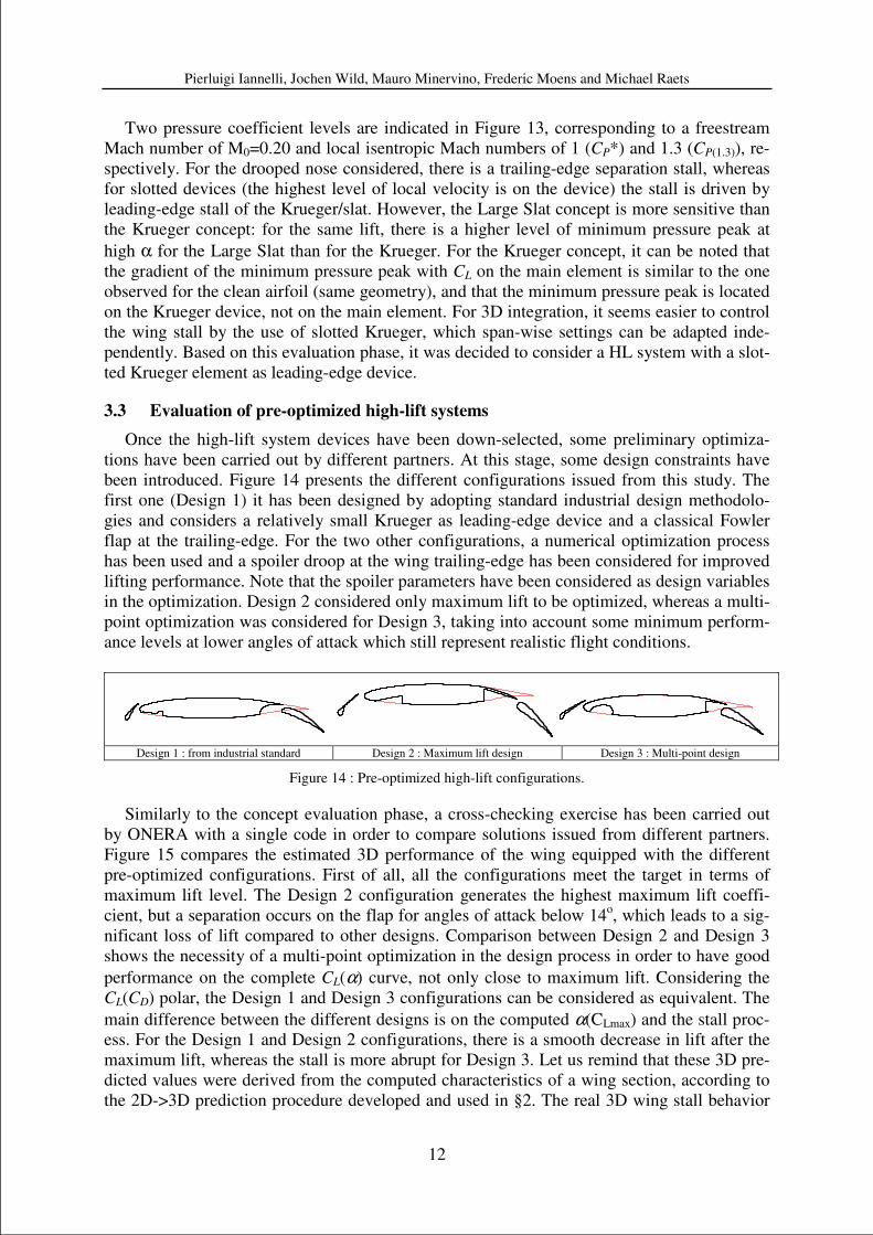
3.3 Evaluation of pre-optimized high-lift systems
Once the high-lift system devices have been down-selected, some preliminary optimiza-
tions have been carried out by different partners. At this stage, some design constraints have
been introduced. Figure 14 presents the different configurations issued from this study. The
first one (Design 1) it has been designed by adopting standard industrial design methodolo-
gies and considers a relatively small Krueger as leading-edge device and a classical Fowler
flap at the trailing-edge. For the two other configurations, a numerical optimization process
has been used and a spoiler droop at the wing trailing-edge has been considered for improved
lifting performance. Note that the spoiler parameters have been considered as design variables
in the optimization. Design 2 considered only maximum lift to be optimized, whereas a multi-
point optimization was considered for Design 3, taking into account some minimum perform-
ance levels at lower angles of attack which still represent realistic flight conditions.
Design 1 : from industrial standard Design 2 : Maximum lift design Design 3 : Multi-point design
Figure 14 : Pre-optimized high-lift configurations.
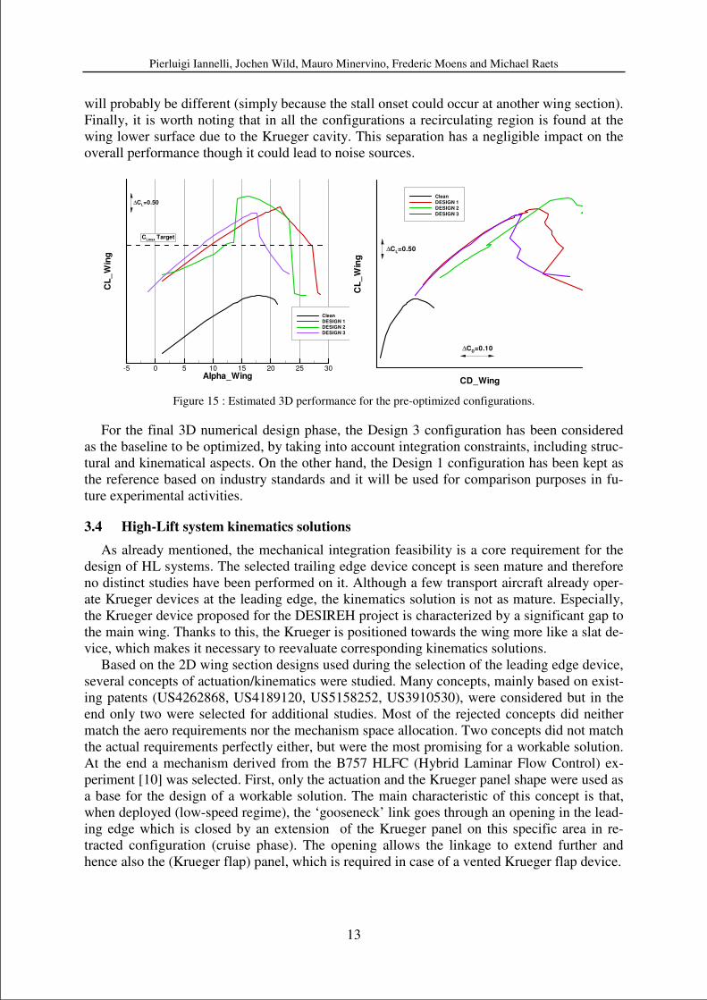
Similarly to the concept evaluation phase, a cross-checking exercise has been carried out
by ONERA with a single code in order to compare solutions issued from different partners.
Figure 15 compares the estimated 3D performance of the wing equipped with the different
pre-optimized configurations. First of all, all the configurations meet the target in terms of
maximum lift level. The Design 2 configuration generates the highest maximum lift coeffi-
cient, but a separation occurs on the flap for angles of attack below 14o, which leads to a sig-
nificant loss of lift compared to other designs. Comparison between Design 2 and Design 3
shows the necessity of a multi-point optimization in the design process in order to have good
performance on the complete CL(α) curve, not only close to maximum lift. Considering the
CL(CD) polar, the Design 1 and Design 3 configurations can be considered as equivalent. The
main difference between the different designs is on the computed α(CLmax) and the stall proc-
ess. For the Design 1 and Design 2 configurations, there is a smooth decrease in lift after the
maximum lift, whereas the stall is more abrupt for Design 3. Let us remind that these 3D pre-
dicted values were derived from the computed characteristics of a wing section, according to
the 2D->3D prediction procedure developed and used in §2. The real 3D wing stall behavior
Pierluigi Iannelli, Jochen Wild, Mauro Minervino, Frederic Moens and Michael Raets
13
will probably be different (simply because the stall onset could occur at another wing section).
Finally, it is worth noting that in all the configurations a recirculating region is found at the
wing lower surface due to the Krueger cavity. This separation has a negligible impact on the
overall performance though it could lead to noise sources.
Alpha_Wing
CL
_W
ing
-5 0 5 10 15 20 25 30
CleanDESIGN 1DESIGN 2DESIGN 3
CLmax
Target
∆CL=0.50
CD_Wing
CL
_W
ing
Clean
DESIGN 1
DESIGN 2
DESIGN 3
∆CL=0.50
∆CD=0.10
Figure 15 : Estimated 3D performance for the pre-optimized configurations.
For the final 3D numerical design phase, the Design 3 configuration has been considered
as the baseline to be optimized, by taking into account integration constraints, including struc-
tural and kinematical aspects. On the other hand, the Design 1 configuration has been kept as
the reference based on industry standards and it will be used for comparison purposes in fu-
ture experimental activities.
3.4 High-Lift system kinematics solutions
As already mentioned, the mechanical integration feasibility is a core requirement for the
design of HL systems. The selected trailing edge device concept is seen mature and therefore
no distinct studies have been performed on it. Although a few transport aircraft already oper-
ate Krueger devices at the leading edge, the kinematics solution is not as mature. Especially,
the Krueger device proposed for the DESIREH project is characterized by a significant gap to
the main wing. Thanks to this, the Krueger is positioned towards the wing more like a slat de-
vice, which makes it necessary to reevaluate corresponding kinematics solutions.
Based on the 2D wing section designs used during the selection of the leading edge device,
several concepts of actuation/kinematics were studied. Many concepts, mainly based on exist-
ing patents (US4262868, US4189120, US5158252, US3910530), were considered but in the
end only two were selected for additional studies. Most of the rejected concepts did neither
match the aero requirements nor the mechanism space allocation. Two concepts did not match
the actual requirements perfectly either, but were the most promising for a workable solution.
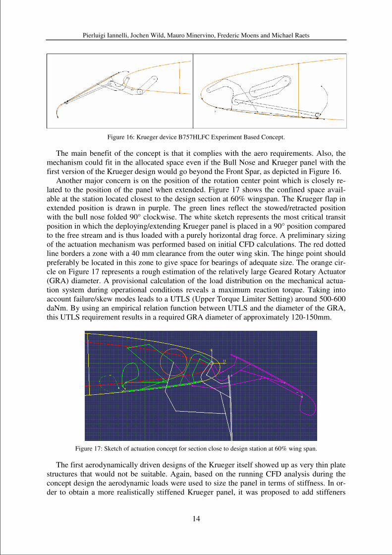
At the end a mechanism derived from the B757 HLFC (Hybrid Laminar Flow Control) ex-
periment [10] was selected. First, only the actuation and the Krueger panel shape were used as
a base for the design of a workable solution. The main characteristic of this concept is that,
when deployed (low-speed regime), the ‘gooseneck’ link goes through an opening in the lead-
ing edge which is closed by an extension of the Krueger panel on this specific area in re-
tracted configuration (cruise phase). The opening allows the linkage to extend further and
hence also the (Krueger flap) panel, which is required in case of a vented Krueger flap device.
Pierluigi Iannelli, Jochen Wild, Mauro Minervino, Frederic Moens and Michael Raets
14
Figure 16: Krueger device B757HLFC Experiment Based Concept.
The main benefit of the concept is that it complies with the aero requirements. Also, the
mechanism could fit in the allocated space even if the Bull Nose and Krueger panel with the
first version of the Krueger design would go beyond the Front Spar, as depicted in Figure 16.
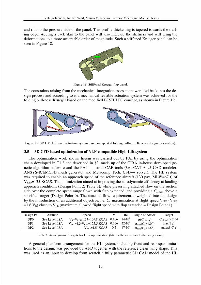
Another major concern is on the position of the rotation center point which is closely re-
lated to the position of the panel when extended. Figure 17 shows the confined space avail-
able at the station located closest to the design section at 60% wingspan. The Krueger flap in
extended position is drawn in purple. The green lines reflect the stowed/retracted position
with the bull nose folded 90° clockwise. The white sketch represents the most critical transit
position in which the deploying/extending Krueger panel is placed in a 90° position compared
to the free stream and is thus loaded with a purely horizontal drag force. A preliminary sizing
of the actuation mechanism was performed based on initial CFD calculations. The red dotted
line borders a zone with a 40 mm clearance from the outer wing skin. The hinge point should
preferably be located in this zone to give space for bearings of adequate size. The orange cir-
cle on Figure 17 represents a rough estimation of the relatively large Geared Rotary Actuator
(GRA) diameter. A provisional calculation of the load distribution on the mechanical actua-
tion system during operational conditions reveals a maximum reaction torque. Taking into
account failure/skew modes leads to a UTLS (Upper Torque Limiter Setting) around 500-600
daNm. By using an empirical relation function between UTLS and the diameter of the GRA,
this UTLS requirement results in a required GRA diameter of approximately 120-150mm.
Figure 17: Sketch of actuation concept for section close to design station at 60% wing span.
The first aerodynamically driven designs of the Krueger itself showed up as very thin plate
structures that would not be suitable. Again, based on the running CFD analysis during the
concept design the aerodynamic loads were used to size the panel in terms of stiffness. In or-
der to obtain a more realistically stiffened Krueger panel, it was proposed to add stiffeners
Pierluigi Iannelli, Jochen Wild, Mauro Minervino, Frederic Moens and Michael Raets
15
and ribs to the pressure side of the panel. This profile thickening is tapered towards the trail-
ing edge. Adding a back skin to the panel will also increase the stiffness and will bring the
deformations to a more acceptable order of magnitude. Such a stiffened Krueger panel can be
seen in Figure 18.
Figure 18: Stiffened Krueger flap panel.
The constraints arising from the mechanical integration assessment were fed back into the de-
sign process and according to it a mechanical feasible actuation system was achieved for the
folding bull-nose Krueger based on the modified B757HLFC concept, as shown in Figure 19.
Figure 19: 3D DMU of sized actuation system based on updated folding bull-nose Krueger design (des.station).
3.5 3D CFD-based optimization of NLF-compatible High-Lift system
The optimization work shown herein was carried out by PAI by using the optimization
chain developed in T1.2 and described in §2, made up of the CIRA in-house developed ge-
netic algorithm software and the PAI industrial CAE tools (i.e., CATIA v5 CAD modeler,
ANSYS-ICEMCFD mesh generator and Metacomp Tech. CFD++ solver). The HL system
was required to enable an approach speed of the reference aircraft (130 pax, MLW=67 t) of
VREF=135 KCAS. The optimization aimed at improving the aerodynamic efficiency at landing
approach conditions (Design Point 2, Table 3), while preserving attached flow on the suction
side over the complete speed range flown with flap extended, and providing a CL,max above a
specified target (Design Point 0). The attached flow requirement is weighted into the design
by the introduction of an additional objective, i.e. CL maximization at flight speed VFE* (VFE*
=1.6·VS) close to VFE (maximum allowed flight speed with flap extended – Design Point 1).
Design Pt. Altitude Speed M Re Angle of Attack Target
DP0 Sea Level, ISA VS=VREF/1.23=109.8 KCAS 0.166 14·106 α(CL,MAX) CL,MAX > 2.54
DP1 Sea Level, ISA VFE*=1.3·VREF=175.5 KCAS 0.266 22·106 αbase(CL=1.00) max(CL)
DP2 Sea Level, ISA VREF=135 KCAS 0.2 17·106 αbase(CL=1.68) max(E
2CL)
Table 3: Aerodynamic Targets for HLS optimization (lift coefficients refer to the wing alone).
A general planform arrangement for the HL system, including front and rear spar limita-
tions to the design, was provided by AI-D together with the reference clean wing shape. This
was used as an input to develop from scratch a fully parametric 3D CAD model of the HL
Pierluigi Iannelli, Jochen Wild, Mauro Minervino, Frederic Moens and Michael Raets
16
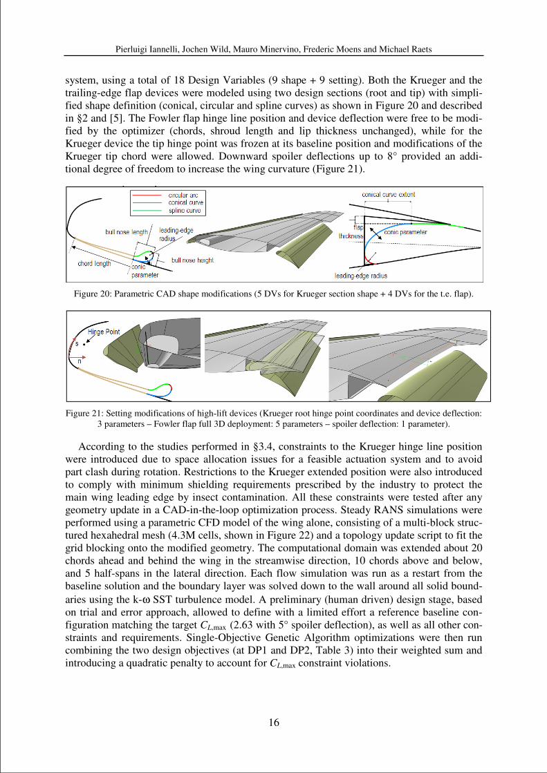
system, using a total of 18 Design Variables (9 shape + 9 setting). Both the Krueger and the
trailing-edge flap devices were modeled using two design sections (root and tip) with simpli-
fied shape definition (conical, circular and spline curves) as shown in Figure 20 and described
in §2 and [5]. The Fowler flap hinge line position and device deflection were free to be modi-
fied by the optimizer (chords, shroud length and lip thickness unchanged), while for the
Krueger device the tip hinge point was frozen at its baseline position and modifications of the
Krueger tip chord were allowed. Downward spoiler deflections up to 8° provided an addi-
tional degree of freedom to increase the wing curvature (Figure 21).
Figure 20: Parametric CAD shape modifications (5 DVs for Krueger section shape + 4 DVs for the t.e. flap).
Figure 21: Setting modifications of high-lift devices (Krueger root hinge point coordinates and device deflection:
3 parameters – Fowler flap full 3D deployment: 5 parameters – spoiler deflection: 1 parameter).
According to the studies performed in §3.4, constraints to the Krueger hinge line position
were introduced due to space allocation issues for a feasible actuation system and to avoid
part clash during rotation. Restrictions to the Krueger extended position were also introduced
to comply with minimum shielding requirements prescribed by the industry to protect the
main wing leading edge by insect contamination. All these constraints were tested after any
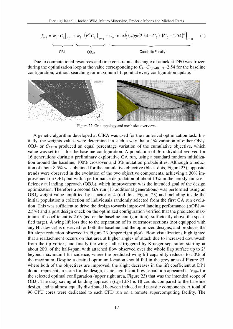
geometry update in a CAD-in-the-loop optimization process. Steady RANS simulations were
performed using a parametric CFD model of the wing alone, consisting of a multi-block struc-
tured hexahedral mesh (4.3M cells, shown in Figure 22) and a topology update script to fit the
grid blocking onto the modified geometry. The computational domain was extended about 20
chords ahead and behind the wing in the streamwise direction, 10 chords above and below,
and 5 half-spans in the lateral direction. Each flow simulation was run as a restart from the
baseline solution and the boundary layer was solved down to the wall around all solid bound-
aries using the k-ω SST turbulence model. A preliminary (human driven) design stage, based
on trial and error approach, allowed to define with a limited effort a reference baseline con-
figuration matching the target CL,max (2.63 with 5° spoiler deflection), as well as all other con-
straints and requirements. Single-Objective Genetic Algorithm optimizations were then run
combining the two design objectives (at DP1 and DP2, Table 3) into their weighted sum and
introducing a quadratic penalty to account for CL,max constraint violations.
Pierluigi Iannelli, Jochen Wild, Mauro Minervino, Frederic Moens and Michael Raets
17
( ) ( ) ( )( )0
2
2
2
211 54.254.2,0maxDP
LLoDP
LDPLobj CCsignwCEwCwf −⋅−⋅+⋅+⋅= (1)
Due to computational resources and time constraints, the angle of attack at DP0 was frozen
during the optimization loop at the value corresponding to CL=CL,TARGET=2.54 for the baseline
configuration, without searching for maximum lift point at every configuration update.
Figure 22: Grid topology and mesh size overview.
A genetic algorithm developed at CIRA was used for the numerical optimization task. Ini-
tially, the weights values were determined in such a way that a 1% variation of either OBJ1,
OBJ2 or CL,DP0 produced an equal percentage variation of the cumulative objective, which
value was set to -1 for the baseline configuration. A population of 36 individual evolved for
16 generations during a preliminary explorative GA run, using a standard random initializa-
tion around the baseline, 100% crossover and 3% mutation probabilities. Although a reduc-
tion of about 8.5% was obtained for the cumulative objective (black dots, Figure 23), opposite
trends were observed in the evolution of the two objective components, achieving a 30% im-
provement on OBJ1 but with a performance degradation of about 13% in the aerodynamic ef-
ficiency at landing approach (OBJ2), which improvement was the intended goal of the design
optimization. Therefore a second GA run (13 additional generations) was performed using an
OBJ2 weight value amplified by a factor of 4 (red dots, Figure 23) and including inside the
initial population a collection of individuals randomly selected from the first GA run evolu-
tion. This was sufficient to drive the design towards improved landing performance (∆OBJ2=-
2.5%) and a post design check on the optimized configuration verified that the predicted max-
imum lift coefficient is 2.63 (as for the baseline configuration), sufficiently above the speci-
fied target. A wing lift loss due to the separation of its outermost sections (not equipped with
any HL device) is observed for both the baseline and the optimized designs, and produces the
lift slope reduction observed in Figure 23 (upper right plot). Flow visualizations highlighted
that a reattachment occurs on that area at higher angles of attack due to increased downwash
from the tip vortex, and finally the wing stall is triggered by Krueger separation starting at
about 20% of the half-span, with attached flow observed over the whole flap surface up to 2°
beyond maximum lift incidence, where the predicted wing lift capability reduces to 50% of
the maximum. Despite a desired optimum location should fall in the grey area of Figure 23,
where both of the objectives are improved, the slight decreases in the lift coefficient at DP1
do not represent an issue for the design, as no significant flow separation appeared at VFE* for
the selected optimal configuration (upper right area, Figure 23) that was the intended scope of
OBJ1. The drag saving at landing approach (CL=1.68) is 18 counts compared to the baseline
design, and is almost equally distributed between induced and parasite components. A total of
96 CPU cores were dedicated to each CFD run on a remote supercomputing facility. The
OBJ1 OBJ2 Quadratic Penalty

Pierluigi Iannelli, Jochen Wild, Mauro Minervino, Frederic Moens and Michael Raets
18
evaluation of each individual over all the DPs required approximately 70 minutes leading to
42 hours elapsed to complete each generation running the GA optimizer in serial mode. Fi-
nally, in Figure 24 it is shown a comparison of optimized versus baseline HL configurations
at the wing root section. An increase of downward spoiler deflection revealed beneficial to the
design and the optimal setting (~7.4 degrees) did not exceed the maximum allowed deflection
of 8 degrees suggested by the industry.
Figure 23: Optimizations evolution in the objectives space, lift curve (at DP0) and skin friction streamtraces (at
DP1) for the optimal configuration.
Figure 24: Baseline vs. Optimized HL configurations at wing root section.
4 CONCLUSIONS
The design and optimization of a high lift system for a High Aspect Ratio Low Sweep
wing featuring Natural Laminar Flow at transonic cruise conditions is targeted in the De-
SiReH project. Within this paper two main areas of investigation have been described, both
dedicated to the application of CFD-based automatic optimization tools currently available
and applied within the aerospace community for HL design purposes.
The first area of investigation was devoted to the analysis of concurrent optimization strat-
egies, by considering a complex realistic problem for a classical three element HL system op-
timization. Based on the information gathered from the different partners’ approaches, it was
BASELINE
OPTIMIZED
Pierluigi Iannelli, Jochen Wild, Mauro Minervino, Frederic Moens and Michael Raets
19
possible to draw up some general guidelines and suggested areas for future investigations.
The first outcome of this study is that the employment of automatic optimization in HL design
can provide larger improvements (a factor of 2) compared to current industrial approaches
based on “by hand” optimization requiring high human interaction and expertise. On the other
hand, the investigations carried out have also revealed that in automatic optimization even an
inadequate exploration of the design space (e.g., due to the usage of a large number of design
variables) can produce at least comparable results to what is obtainable with the above indus-
trial approach. In this context, the usage of meta-models can improve automatic optimization
tools in the sense of a faster and wider exploration of large design spaces or, on the other hand,
a simplification of the problem wherever sequentialization/decoupling strategies are applica-
ble. As observed, not all the strategies aimed at reducing the design space are effective and
suitable strategies must be assessed a-priori by preliminary analyses or pre-knowledge of the
HL optimization problem. With reference to this, the employment of “engineering-
knowledge” optimization strategies based on the observation of suitable physical sensors has
proven to be very powerful and cost-effective. Finally, the coupling of a research-developed
optimization software with currently available industrial CFD tools revealed to be successful
and feasible in performing a fully automatic 3D HL optimization of industrial interest.
The experience gained in the first part of the DeSiReH project was exploited in a second
phase, wherein the design of a HL system was carried for a future transport aircraft adopting a
HARLS wing featuring NLF at transonic cruise conditions. In a first exploratory phase sev-
eral leading edge HL concepts (i.e. the slotted Krueger, the Large Slat and the Drooped Nose)
have been pre-optimized to achieve a target CL,max without including feasibility constraints.
The slotted Krueger concept was down-selected, according to the achieved performance in
terms of CL,max, drag, impact on laminarity and leading edge insect shielding properties. Then,
three different designs have been generated for the selected slotted Krueger+Fowler flap sys-
tem: one design is based on standard procedures used in industry (driven by high-lift aerody-
namics expertise) and two other designs were carried out by using automatic numerical
optimization working with different formulations of the problem. Between these last two de-
signs, one was selected (according to aerodynamic criteria based on CL,max, αmax, CD, CL be-
havior in the full flight envelope) to generate an initial 3D wing HL model, to be further
optimized by means of the 3D CFD optimization tools settled up in the first part of the project.
During this phase, several kinematics, mechanical integration feasibility and structural sizing
studies have been conducted by also exploiting the CFD generated aerodynamic data, in order
to continuously supply the optimizing partners with as much as possible realistic constraints.
The final part of the design phase was then dedicated to the 3D automatic optimization with
all the constraints included and aimed at improving the aerodynamic efficiency at landing and
approach conditions, while preserving attached flow on the flap over the complete speed
range and providing a CL,max above a specified target. The 3D optimization work required an
intensive usage of computational resources which anyway seem to be of affordable level for
the aerospace industry nowadays or in the near future.
In the following of the DeSiReH project the developed 3D high-lift models based on both
industrial expertise and automatic optimization, respectively, will be tested in the European
Transonic Wind Tunnel at low-speed and flight Reynolds numbers. This experimental cam-
paign will be used to assess the predicted aerodynamic performance of the designed HL sys-
tems and to quantify, in a realistic framework, the added value of using automatic CFD
optimization to design aircraft high-lift devices.
Pierluigi Iannelli, Jochen Wild, Mauro Minervino, Frederic Moens and Michael Raets
20
ACKNOWLEDGEMENT
This work has been performed within the scope of the DESIREH project funded by the Eu-
ropean 7th Framework Programme under grant number ACP8-GA-2009-233607. Special
thanks to the consortium of the European 7th Framework Programme TELFONA, especially
David Sawyers, Airbus UK, for providing the laminar clean wing shape for the investigations
within this project. The authors are also grateful to Henning Strueber, Airbus-Germany, for
providing a continuous industrial feedback to the HARLS wing HL optimization working
group and to Domenico Quagliarella, CIRA, who was strongly involved in the integration of
the CIRA in house developed GA optimizer with Piaggio Aero Industries CAE tools.
REFERENCES
[1] European Commission: "Aeronautics and Air Transport Research - 7th Framework Pro-
gramme 2007-2013", European Union, ISBN 978-92-79-14287-1 (2012), pp. 34-36.
[2] J. Ponsin, M. Meheut: Comparison of Grid Adaptation Techniques for High-Lift Flow
Applications. ECCOMAS 2012 Conference, Aeronautics Special Technology Session,
STS01: Progress in CFD for High-Lift Application and Design.
[3] P. Eliasson, C. Marongiu, S. Bosnyakov: Acceleration of URANS for application to
separated high-lift flows. ECCOMAS 2012 Conference, Aeronautics Special Technol-
ogy Session, STS01: Progress in CFD for High-Lift Application and Design.
[4] P. Iannelli, D. Quagliarella: Multi-objective/Multi-point shape and setting high-lift sys-
tem optimization by means of genetic algorithm and 2D Navier-Stokes equations.
EUROGEN 2011 Conference proceedings, Capua, Italy.
[5] M. Minervino, P. Iannelli, D. Quagliarella: 3D Flap design using Navier-Stokes equa-
tions and evolutionary optimization techniques on an industrial platform. EUROGEN
2011 Conference proceedings, Capua, Italy.
[6] E. Benini, R.Ponza, P. Iannelli, H. Strüber, Z. Hrncir, F. Moens and T. Kuehn: Multi-
point shape and setting optimization of high-lift airfoils in both take-off and landing
conditions. ECCOMAS 2012 Conference proceedings, TO-28, Vienna, Austria.
[7] J. Wild, J. Brezillon, O. Amoignon, J. Quest, F. Moens, D. Quagliarella: Advanced de-
sign by numerical methods and wind-tunnel verification within European high-lift pro-
gram. Journal of Aircraft, Vol. 46, No. 1, January–February 2009.
[8] F. Moens, C. Wervaecke: Multi-point optimization of shapes and settings of high-lift
system by means of evolutionary algorithm and Navier-Stokes equations. Submitted to
Journal of Engineering Computations, Special Issue on Computational Methods in En-
gineering Design and Optimization, 2012.
[9] A.M.O. Smith: High-Lift Aerodynamics. Journal of Aircraft. Vol. 12, No6, June 1975.
[10] P.K.C. Rudolph: High-Lift Systems on Commercial Subsonic Airliners. NASA CR4746,
September 1996.