An investigation of the energy storage properties of a 2D ...
22
An investigation of the energy storage properties of a 2D α-MoO 3 -SWCNTs composite films Beatriz Mendoza-S´ anchez a,* , Damien Hanlon b , Jo˜ao Coelho a , Sean O’ Brien b , Henrik Pettersson b , Jonathan Coleman c , and Valeria Nicolosi d,* a Trinity College Dublin, School of Chemistry and CRANN, Dublin 2, Ireland b Trinity College Dublin, School of Physics, Dublin 2, Ireland c Trinity College Dublin, School of Physics, CRANN and AMBER, Dublin 2, Ireland d Trinity College Dublin, Schools of Chemistry, Physics, CRANN and AMBER, Dublin 2, Ireland Abstract 2D α-MoO 3 was synthesized using a facile, inexpensive and scalable liquid- phase exfoliation method. 2D α-MoO 3 /SWCNT (85 wt%/15 wt%) compos- ite films were manufactured by vacuum filtration and their energy storage properties were investigated in a LiClO 4 /propylene carbonate electrolyte in a 1.5 V to 3.5 V vs. Li + /Li electrochemical window. Cyclic voltammetry showed typical ion intercalation peaks of α-MoO 3 and a capacitance of 200 Fg -1 was achieved at 10 mV s -1 and 82 F g -1 at 50 mV s -1 . The com- posite electrodes achieved a capacitive charge storage of 375 C g -1 and a diffusion-controlled maximum charge storage of 703 C g -1 . The latter being superior to the charge storage achieved by previously reported mesoporous α-MoO 3 , produced using more cumbersome multi-step templating methods, and α-MoO 3 nanobelts . This superior Li-ion intercalation charge storage * Corresponding authors Email addresses: [email protected] (Beatriz Mendoza-S´ anchez ), [email protected] (and Valeria Nicolosi)
Transcript of An investigation of the energy storage properties of a 2D ...
An investigation of the energy storage properties of a
2D α-MoO3-SWCNTs composite films
Beatriz Mendoza-Sancheza,∗, Damien Hanlonb, Joao Coelhoa, Sean O’Brienb, Henrik Petterssonb, Jonathan Colemanc, and Valeria Nicolosid,∗
aTrinity College Dublin, School of Chemistry and CRANN, Dublin 2, IrelandbTrinity College Dublin, School of Physics, Dublin 2, Ireland
cTrinity College Dublin, School of Physics, CRANN and AMBER, Dublin 2, IrelanddTrinity College Dublin, Schools of Chemistry, Physics, CRANN and AMBER, Dublin 2,
Ireland
Abstract
2D α-MoO3 was synthesized using a facile, inexpensive and scalable liquid-
phase exfoliation method. 2D α-MoO3/SWCNT (85 wt%/15 wt%) compos-
ite films were manufactured by vacuum filtration and their energy storage
properties were investigated in a LiClO4/propylene carbonate electrolyte in
a 1.5 V to 3.5 V vs. Li+/Li electrochemical window. Cyclic voltammetry
showed typical ion intercalation peaks of α-MoO3 and a capacitance of 200
F g−1 was achieved at 10 mV s−1 and 82 F g−1 at 50 mV s−1. The com-
posite electrodes achieved a capacitive charge storage of 375 C g−1 and a
diffusion-controlled maximum charge storage of 703 C g−1. The latter being
superior to the charge storage achieved by previously reported mesoporous
α-MoO3, produced using more cumbersome multi-step templating methods,
and α-MoO3 nanobelts . This superior Li-ion intercalation charge storage
∗Corresponding authorsEmail addresses: [email protected] (Beatriz Mendoza-Sanchez ),
[email protected] (and Valeria Nicolosi)
was attributed to the shorter ion-transport paths of 2D α-MoO3 as com-
pared to other nanostructures. Galvanostatic charge-discharge experiments
showed a maximum charge storage of 123.0 mAh g−1 at a current density of
100 mA g−1.
Keywords:
2D α-MoO3, single-walled carbon nanotubes, energy storage, Li-ion
intercalation
1. Introduction
Due to its properties, α-MoO3 is an attractive material for energy storage
applications. Firstly, α-MoO3 has a layered crystal structure suitable for ion
intercalation. Each layer of the 2D-layered structure of orthorhombic α-
MoO3 is composed of two octahedron nets that share O-O edges along the
[001] direction and corners along the [100] direction, and each layer is linked
to an adjacent layer by van der Waals forces along the [010] direction [1, 2].
Secondly, due to the high oxidation state of the metal (Mo6+) in α-MoO3, this
material has high open circuit potential, and thus, it is capable of high energy
storage when tested in a typical battery set up [3]. Thirdly, due to the various
oxidation states of Mo (Mo6+, Mo5+, Mo4+, Mo3+), α-MoO3 can store energy
by undergoing redox activity [4, 5]. α-MoO3 has mainly been investigated
as a battery cathode[3, 6–8] and anode [9, 10] and a high charge storage
has been reported. However, drawbacks preventing its application include:
characteristic slow kinetics, high irreversibility and poor cycle stability. More
recently, α-MoO3 has been investigated as a supercapacitor electrode in a Li-
ion based electrolyte and a high charge storage attributed to pseudocapacitive
2
activity was reported [11]. However, the study did not include cycle stability
assessment.
In order to improve charge storage capacity, α-MoO3 has been nanos-
tructured and combined with carbon-based materials. The literature re-
ports various α-MoO3 nanostructures including nanoparticles, nanowires and
mesoporous nanostructures [9–11] with high surface areas and/or porosity
that enables a greater charge storage than their micro-sized counterparts.
Due to its semiconducting nature, α-MoO3 stores charge poorly unless it is
provided with an electrically conducting additive. Carbon-based materials
such as carbon nanotubes and carbon black are added as conductive addi-
tives [9, 12]. Upon repeated Li-ion intercalation de-intercalation, α-MoO3
expands and contracts eventually causing particle pulverization and loss of
particle-particle contact [13]. This leads to capacity fading upon cycling.
Carbon-based additives not only provide suitable electrical conductivity but
also are used to alleviate this pulverization effect serving as a “mechanical
buffer” of α-MoO3 particles[13, 14]. Carbon nanotubes, for example, form
nets that buffer volume changes during cycling [12].
2D nanomaterials are typically obtained from layered van der Waals solids
that have strong ionic or covalent in-plane bonds that form layers but weak
out-of-plane van der Waals bonds [15, 16]. The term “exfoliation” refers
to the delamination of layered van der Waals solids by overcoming the van
der Waals forces by either shearing parallel or expanding normal to the in-
plane direction [15, 16]. Liquid-phase exfoliation utilizes ultrasonic energy
and liquid-mediated stabilization to delaminate layered van der Waals solids,
resulting in exfoliated nanosheets (the term nano refers to the magnitude of
3
the thickness) [17, 18]. Liquids, including water and organic solvents, with
the correct surface energy or solubility parameters bind by van der Waals
interactions to the exfoliated nanosheets with strengths that are similar to
the inter-nanosheet binding strength, preventing re-aggregation and reducing
the net energy cost of exfoliation [19–21]. In the ideal case, the nanosheets are
comprised of a single constituent layer of the original layered solid; however,
in practice, the nanosheets consist of few (≈ 10) stacked layers [17].
2D nanomaterials produced by liquid-phase exfoliation offer some scope
for application in batteries and supercapacitors due to: (1) high surface area
with a typical width of 50 nm, length < 1000 nm, and thickness < 2 - 5
nm [18, 22] (2) high packing density that allows volume reduction of devices,
highly relevant in the power electronics industry where miniaturization is
important, (3) redox and/or ion-intercalation activity, (4) cost-effectiveness,
simplicity and scalability of the liquid-phase exfoliation method, (5) produc-
tion of the 2D nanomaterials in suspension which allows immediate process-
ability into films using scalable methods such as spray-deposition [23, 24] and
ink-jet printing.
In this work, commercially available bulk layered α-MoO3 was exfoli-
ated in isopropanol resulting in α-MoO3 nanosheets (2D α-MoO3) of 400
nm length x 100 nm width x 21 nm thickness. Characterization of the 2D
α-MoO3 has been addressed elsewhere [25]. The 2D α-MoO3 were combined
with single-walled carbon nanotubes (SWCNTs) (85 wt%/15 wt% ratio) in
composite film electrodes and their energy storage properties were investi-
gated in a LiClO4/propylene carbonate electrolyte in a 1.5 V to 3.5 V vs.
Li+/Li electrochemical window. The composite electrodes achieved a higher
4
Li-ion intercalation charge storage (703 C g−1) than other nanostructures, a
maximum capacitance of 200 F g−1 at 10 mV s−1, and a capacity of 123.0
mAh g−1 at a current density of 100 mA g−1.
2. Experimental
2.1. Materials
Single-walled carbon nanotubes (SWCNTs) functionalized with 1-3 wt%
carboxylic groups (“P3-SWNT”) were supplied by Carbon Solutions Inc
(USA); MoO3 powder (99.98 %, CAS 1313-27-5), isopropanol (IPA 99.9 %),
Li wire (≥ 98 % in mineral oil), n-hexane (anhydrous 95 %), lithium per-
chlorate (battery grade 99.99 %), and propylene carbonate (anhydrous 99.7
%) were supplied by Sigma Aldrich (Ireland); poly (ethyleneimine) (PEI,
Mw= 70,000 ) was supplied by Alfa-Aesar (UK); aluminium foil of 0.025
mm thickness (temper hard Al000420) was supplied by GoodFellow (UK);
alumina membrane filters (Anodisc 47, 0.02 µm pore size, Whatman) and
nitrocellulose membrane filters (0.02 µm pore size, 10 mm diameter, Milli-
pore) were supplied by Fisher (Ireland).
2.2. Preparation of 2D α-MoO3 dispersion
A dispersion of 2D α-MoO3 in IPA was first prepared by liquid-phase
exfoliation. MoO3 powder (30 g) was added to IPA (100 mL) in a 140 ml
open top, flat bottomed beaker. The mix was ultrasonicated for 5 hours in a
VCX-750 sonic dismembrator (25 % amplitude and operated under pulsation
mode, 9 s on and 2 s off). The beaker was connected to an external cooling
system (circulator refrigerated bath) that maintained water at 5 ◦C circulat-
ing around the beaker during ultrasonication. The resulting dispersion was
5
then centrifuged at 1,500 rpm (RCF = 240) for 110 min. A dispersion of 2D
α-MoO3 in IPA was finally obtained by collecting the supernatant (top 75
%) using a volumetric pipette. The concentration of the 2D α-MoO3 disper-
sion (0.17 mg ml−1) was determined by weighing before and after vacuum
filtration onto an alumina membrane filter (pore size 0.02 µm).
2.3. Preparation of 2D α-MoO3/SWCNT composite dispersion
A dispersion of 2D α-MoO3 in IPA was prepared as described above.
SWCNTs (5 mg) were dispersed in IPA (50 mL) at a concentration of 0.1 mg
ml−1. This suspension was then ultrasonicated for 30 min in a VCX-750 sonic
dismembrator (40 % amplitude) while cooling down, then ultrasonicated for
one hour in a ElmasonicP120H sonic bath (37 kHz, 60 % power) followed by
an additional 30 min in the VCX-750 sonic dismembrator. This dispersion
was then mixed without centrifugation with a 2D-MoO3/IPA dispersion of
predetermined concentration to form a composite of known SWCNTs wt %.
2.4. Electrode manufacture
The 2D α-MoO3/SWCNT composite dispersion was vacuum filtrated us-
ing a nitrocellulose membrane filter and dried at room temperature. These
films were subsequently transferred onto aluminum foil substrates (pre-coated
by spray deposition with a ≈ 5 nm layer of 0.1 % wt/wt PEI solution in wa-
ter) using the transfer method of Wu et al.[26]. The electrodes were then cut
into 18 mm discs. The average mass and thickness of the 2D-MoO3-SWCNT
composite electrodes were 0.7 mg and 1 µm respectively. Electrodes of solely
2D α-MoO3 were manufactured following the same procedure.
6
Equipment and characterization techniques. Transmission elec-
tron microscopy (TEM) images were obtained using a FEI-Titan operated
at 300 keV; scanning electron microscopy (SEM) images were obtained using
a Carl Zeiss Ultra Plus operated at an acceleration voltage of 5 kV; Ra-
man (RS) spectra were recorded at room temperature using a Witec Alpha
300 system with a laser excitation wavelength of 532 nm. Laser power of
≈ 0.4 mW was used with a 20x objective lens. Spectra were acquired for
each sample by averaging 25 distinct spectra, each with an acquisition time
of 30 s; Spray deposition of PEI on substrates was performed using a USI
Prism Ultracoat 300 spray deposition equipment; ultrasonication was per-
formed in a VCX-750 (VibraCell) sonic dismembrator with a 0.5 inch probe
(maximum delivery power of 750 W and operating frequency of 20 kHz),
and an ElmasonicP120H (Fisher FB11207) sonic bath (effective power of
330 W and 37/80 kHz operating frequency); cooling during ultrasonication
was performed with a circulator Isouk 4100 R20 refrigerated bath (Fisher
FB60818); centrifugation was performed in a Hettich Mikro 220R centrifuge
with a fixed angle rotor 1060. The rotational speed ω (rpm) and the rela-
tive centrifugal force (non-dimensional, relative to g = 9.8 m s−2) are both
quoted and related by RCF = 106.4 x 10⁻⁶ω2; electrode thickness was de-
termined by step height measurements in a Dektak 6M profilometer (Veeco
Instruments, Inc) and the weight of deposited films was measured using a
Sartorius Ultramicrobalance MSE-2.7S-000-DF with a 0.0001 mg readabil-
ity; the surface area of the 2D α-MoO3 was determined with a Autosorb iQ
(Quantachrome) gas sorption analyzer to read nitrogen adsorption isotherms
and using the Brunauer-Emmett-Teller (BET) method; electrochemical mea-
7
surements were performed with a Reference 600/EIS300 Gamry potentio-
stat/galvanostat; the electrodes were tested in a three-electrode configura-
tion using an ECC-Combi (EL-CELL, Germany) battery test cell. The cell
assembly was performed in a MB-Unilab (1200/780) (MBRAUN, Germany)
glove box workstation; electrical conductivity was calculated using a four
probe method with a Keithley 2400 source metre. Silver contacts were used
with spacings of about 1 mm.
Electrochemical characterization. 2D α-MoO3/SWCNT electrodes were
tested in a three-electrode electrochemical cell configuration using a Refer-
ence 600/EIS300 Gamry potentiostat/galvanostat; Li wire and Li ribbon as
reference and counter electrodes, respectively; glass fibre separators (1.55
mm thickness, 18 mm diameter); and 1 M LiClO4 in propylene carbonate as
the electrolyte. The cells were assembled in a glove box workstation main-
taining H2O and O2 levels below 0.1 ppm. The electrodes were dried in
vacuum (100 ◦C for 1 hour) prior to the electrochemical tests and the Li
wire was freed of protective mineral oil by extensive rinsing with n-hexane.
Cyclic voltammetry experiments and galvanostatic charge-discharge experi-
ments were performed in a potential range of 1.5 to 3.5 V vs. Li/Li+.
3. Results and discussion
3.1. Characterization of Materials
Characterization of the 2D α-MoO3 by TEM, SEM and Raman were re-
ported in our previous work [25]. Here we describe some aspects relevant to
the energy storage application of 2D α-MoO3. As shown in Figure 1a, the
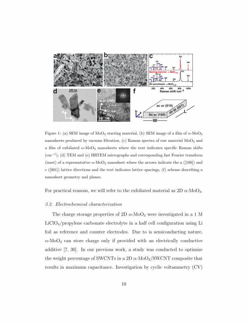
starting material consisted of microsized platelets. Figure 1d shows TEM mi-
8
crographs of the liquid-phase exfoliated 2D α-MoO3 with typical dimensions
of 400 nm length x 100 nm width x 21 nm thickness (mean size determined
by atomic force microscopy measurements over 100 nanosheets) [25]. The
high-resolution TEM (HRTEM) image in Figure 1e show the high structural
quality of the as synthesized nanoshets. The fast Fourier transform (FFT)
(inset of Figure 1e) shows that the lattice spacings correspond to the alpha
phase of MoO3. The viewing direction of the HRTEM image (see scheme
in Figure 1f) is along the [010] zone axis. The (010) planes are shown with
lattice spacings of 0.36 nm along the [001] direction (edge sharing along the c
axis, i.e. the nanosheet width) and 0.38 nm along the [100] direction (corner
sharing along the a axis, i.e. the nanosheet length).
Raman spectroscopy was performed on the powder of the starting mate-
rial (SEM image shown in Figure 1a) and on a thin film (SEM image shown
in Figure 1b) of as-synthesized material. Figure 1c shows the Raman spectra
(excitation wavelength of 532 nm) of both samples. Both spectra showed
characteristic bands of the orthorhombic phase of MoO3 [27–29]: 996 cm−1,
820 cm−1, 666-667 cm−1, 480 cm−1, 380 cm−1, 366 cm−1, 338 cm−1, 291 cm−1,
285 cm−1, 245 cm−1, 217 cm−1, 197 cm−1, and 158 cm−1. The stoichiometry
of the samples was determined by following the methodology of Dieterle et
al. where the ratio of intensities of the band at 285 cm−1 to that at 295 cm−1
is correlated to the stoichiometry [27]. Here the latter band was shifted
to 291 cm−1, indicating the presence of oxygen vacancies. Applying this
analysis, the stoichiometry of starting material and exfoliated material were
determined as MoO2.96 and MoO2.95 respectively [25]. Therefore, a negligible
amount of oxygen vacancies were introduced by the exfoliation procedures.
9
200 nm
fe
a or [100]
c or [001]
100 nm
a a
c
bbc or (100)
ab or (001)ac or (010)
d
a b c
c
L
W
Figure 1: (a) SEM image of MoO3 starting material, (b) SEM image of a film of α-MoO3
nanosheets produced by vacuum filtration, (c) Raman spectra of raw material MoO3 and
a film of exfoliated α-MoO3 nanosheets where the text indicates specific Raman shifts
(cm−1), (d) TEM and (e) HRTEM micrographs and corresponding fast Fourier transform
(inset) of a representative α-MoO3 nanosheet where the arrows indicate the a ([100]) and
c ([001]) lattice directions and the text indicates lattice spacings, (f) scheme describing a
nanosheet geometry and planes.
For practical reasons, we will refer to the exfoliated material as 2D α-MoO3.
3.2. Electrochemical characterization
The charge storage properties of 2D α-MoO3 were investigated in a 1 M
LiClO4/propylene carbonate electrolyte in a half cell configuration using Li
foil as reference and counter electrodes. Due to is semiconducting nature,
α-MoO3 can store charge only if provided with an electrically conductive
additive [7, 30]. In our previous work, a study was conducted to optimize
the weight percentage of SWCNTs in a 2D α-MoO3/SWCNT composite that
results in maximum capacitance. Investigation by cyclic voltammetry (CV)
10
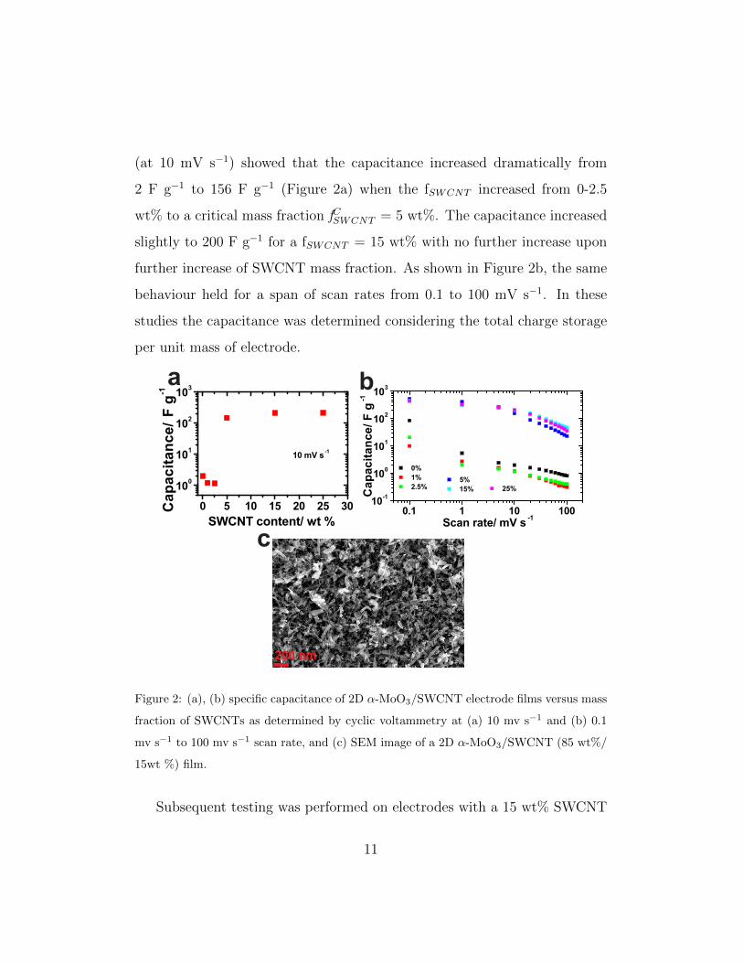
(at 10 mV s−1) showed that the capacitance increased dramatically from
2 F g−1 to 156 F g−1 (Figure 2a) when the fSWCNT increased from 0-2.5
wt% to a critical mass fraction fCSWCNT = 5 wt%. The capacitance increased
slightly to 200 F g−1 for a fSWCNT = 15 wt% with no further increase upon
further increase of SWCNT mass fraction. As shown in Figure 2b, the same
behaviour held for a span of scan rates from 0.1 to 100 mV s−1. In these
studies the capacitance was determined considering the total charge storage
per unit mass of electrode.
200 nm
a b
c
Figure 2: (a), (b) specific capacitance of 2D α-MoO3/SWCNT electrode films versus mass
fraction of SWCNTs as determined by cyclic voltammetry at (a) 10 mv s−1 and (b) 0.1
mv s−1 to 100 mv s−1 scan rate, and (c) SEM image of a 2D α-MoO3/SWCNT (85 wt%/
15wt %) film.
Subsequent testing was performed on electrodes with a 15 wt% SWCNT
11
content. The SEM image in Figure 2c shows the surface of 2D α-MoO3/SWCNT
(85 wt%/ 15 wt%) composite electrode, where a high degree of interleaving
of the SWCNTs in between and around the MoO3 nanosheets had been
achieved, not only developing an electrically conducting network, but also
providing a degree of mesoporosity desirable to facilitate electrolyte accessi-
bility [12].
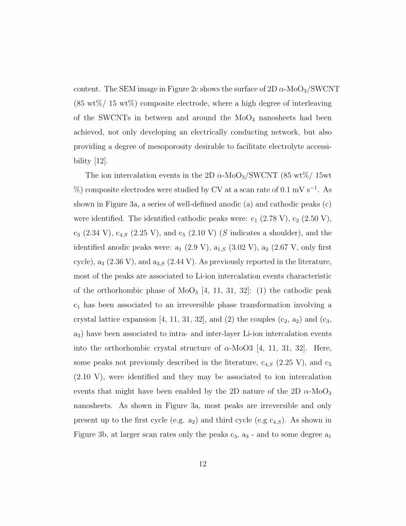
The ion intercalation events in the 2D α-MoO3/SWCNT (85 wt%/ 15wt
%) composite electrodes were studied by CV at a scan rate of 0.1 mV s−1. As
shown in Figure 3a, a series of well-defined anodic (a) and cathodic peaks (c)
were identified. The identified cathodic peaks were: c1 (2.78 V), c2 (2.50 V),
c3 (2.34 V), c4,S (2.25 V), and c5 (2.10 V) (S indicates a shoulder), and the
identified anodic peaks were: a1 (2.9 V), a1,S (3.02 V), a2 (2.67 V, only first
cycle), a3 (2.36 V), and a3,S (2.44 V). As previously reported in the literature,
most of the peaks are associated to Li-ion intercalation events characteristic
of the orthorhombic phase of MoO3 [4, 11, 31, 32]: (1) the cathodic peak
c1 has been associated to an irreversible phase transformation involving a
crystal lattice expansion [4, 11, 31, 32], and (2) the couples (c2, a2) and (c3,
a3) have been associated to intra- and inter-layer Li-ion intercalation events
into the orthorhombic crystal structure of α-MoO3 [4, 11, 31, 32]. Here,
some peaks not previously described in the literature, c4,S (2.25 V), and c5
(2.10 V), were identified and they may be associated to ion intercalation
events that might have been enabled by the 2D nature of the 2D α-MoO3
nanosheets. As shown in Figure 3a, most peaks are irreversible and only
present up to the first cycle (e.g. a2) and third cycle (e.g c4,S). As shown in
Figure 3b, at larger scan rates only the peaks c3, a3 - and to some degree a1
12
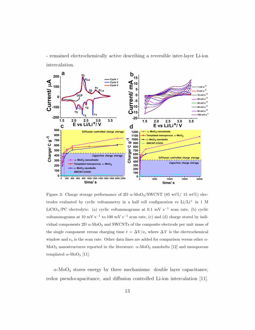
- remained electrochemically active describing a reversible inter-layer Li-ion
intercalation.
a b
c d
Figure 3: Charge storage performance of 2D α-MoO3/SWCNT (85 wt%/ 15 wt%) elec-
trodes evaluated by cyclic voltammetry in a half cell configuration vs Li/Li+ in 1 M
LiClO4/PC electrolyte: (a) cyclic voltammograms at 0.1 mV s−1 scan rate, (b) cyclic
voltammograms at 10 mV s−1 to 100 mV s−1 scan rate, (c) and (d) charge stored by indi-
vidual components 2D α-MoO3 and SWCNTs of the composite electrode per unit mass of
the single component versus charging time t = ∆V/νs where ∆V is the electrochemical
window and νs is the scan rate. Other data lines are added for comparison versus other α-
MoO3 nanostructures reported in the literature: α-MoO3 nanobelts [12] and mesoporous
templated α-MoO3 [11].
α-MoO3 stores energy by three mechanisms: double layer capacitance,
redox pseudocapacitance, and diffusion controlled Li-ion intercalation [11].
13
The first two mechanisms are fast whereas ion intercalation is slower due to
diffusion control. Capacitive contributions to charge storage can be consid-
ered to occur at a 20-100 s time scale (100 mV s−1 to 20 mV s−1 CV scan
rate) [11]. Charge storage contributions controlled by diffusion, i.e. ion in-
tercalation, can be considered to occur at a 100-20,000 s time scale (20 mV
s−1 to 0.1 mV s−1 CV scan rate) [11]. Figures 3c and 3d show the charge
storage capacity of 2D α-MoO3 (charge of the 2D α-MoO3 component in a
composite electrode per unit mass of 2D α-MoO3) as a function of charging
time, as determined by CV. For a given charging time, the overall charge
storage is the sum of the capacitive plus the diffusion controlled contribu-
tions. For times shorter than 100 s (to the left of the vertical dotted line)
there is only a capacitive contribution.
The performance of 2D α-MoO3 was compared to the performance of
previously reported α-MoO3 nanobelts [12] and templated mesoporous α-
MoO3 [11]. The capacitive contribution to the charge storage capacity of
2D α-MoO3 was 375 C g−1 (100 s charging time), which was larger than
that of α-MoO3 nanobelts (349 C g−1) and smaller than that of templated
mesoporous α-MoO3 (450 C g−1). The different BET surface areas of the
various nanostructures considered (13.7 m2 g−1 for nanobelts < 34.3 m2 g−1
for nanosheets < 200 m2 g−1 for mesoporous α-MoO3) may explain the dif-
ference on the capacitive contribution to energy storage. The charge storage
capacity of 2D α-MoO3 due to diffusion controlled processes was 703 C g−1
(20,000 s), 365 C g−1 (2,000 s), 213 C g−1 (400 s) and 115 C g−1 (200 s). As
shown in Figures 3c and 3d (yellow area of the plot), these values are much
higher than those of α-MoO3 nanobelts (e.g. 263 C g−1 at 2,000 s charging
14
time) and templated mesoporous α-MoO3 (e.g. 155 C g−1 at 2,000 s charging
time). This effect can be attributed to: (1) shorter transport paths of 2D
α-MoO3 (400 nm length x 100 nm width) as compared to α-MoO3 nanobelts
(300-400 nm width and 8-18 µm length) for Li-ions to intercalate between
van der Waals gaps (approximately 29 gaps for a 21 nm thick nanosheet if
the lattice spacing is b = 1.38 nm) accessed through the ab and bc planes of
the nanosheets (Figure 1f) exposed to the electrolyte, and (2) the role of the
SWCNTS providing an electrically conducting network and creating a degree
of mesoporosity throughout the electrode, thereby facilitating electrolyte ac-
cess. As shown in Figures 3c and 3d, the charge storage contribution of
SWCNTs to the total electrode charge storage was negligible accounting for
a maximum of 2.5 %.
The capacitive performance as a function of CV scan rate was investi-
gated. Figure 3b shows the CVs at the different scan rates and Figure 2b
shows that the 2D α-MoO3/SWCNT (85 wt%/ 15 wt%) composite electrodes
achieved a capacitance of 200 F g−1 at a scan rate of 10 mV s−1 (200 s) and
was maintained at 82 F g−1 at a scan rate of 50 mV s−1. This performance
is comparable to that achieved by other pseudocapacitive systems including
iron oxides and manganese oxides [33–36].
The cycling stability of the 2D α-MoO3/SWCNT (85 wt%/ 15 wt%) com-
posite electrode was investigated by galvanostatic charge-discharge curves at
a current rate of 100 mA g−1 (0.017 mA cm−2 for an electrode of 2.54 cm2).
A discharge capacity of 123.0 mAh g−1 was achieved during the first cycle.
The capacitance retention over 200 cycles was 62%.
15
4. Conclusions
2D α-MoO3 was synthesized by liquid-phase exfoliation. 2D α-MoO3/SWCNT
(85 wt%/ 15 wt%) composite electrodes were manufactured and their charge
storage properties were investigated. Cyclic voltammetry showed typical ion
intercalation peaks of α-MoO3, and a capacitance of 200 F g−1 was achieved
at 10 mV s−1 and 82 F g−1 at 50 mV s−1. The composite electrodes achieved
a capacitive charge storage of 375 C g−1 and a diffusion-controlled maximum
charge storage of 703 C g−1. The latter being superior to the charge stor-
age achieved by α-MoO3 nanobelts (263 C g−1) and mesoporous α-MoO3
(155 C g−1). This superior charge storage due to Li-ion intercalation was
attributed to shorter ion-transport paths in 2D α-MoO3 as compared to
α-MoO3 nanobelts. Galvanostatic charge-discharge experiments showed a
maximum charge storage of 123.0 mAh g−1 at a current density of 100 mA
g−1. We can conclude that 2D α-MoO3 achieved considerable charge storage
in the long time regime (100 s-20,000 s) offering potential for applications
in batteries. However, this is contingent on improving cycling stability. The
capacitive charge storage was superior to that of α-MoO3 nanobelts and
comparable to the performance of other metal oxide nanostructures. Liquid-
phase exfoliation is a method to produce active materials that offers clear
advantages of cost-effectiveness, ease of processing, and scalability over more
cumbersome and expensive templating and hydrothermal synthetic methods.
Acknowledgements
The authors would like to thank the Advanced Microscopy Laboratory
and CRANN for access to their facilities. VN wish to acknowledge support
16
from the European Research Council (ERC Starting Grant 2DNanoCaps,
ERC 2D USD), FP7 ITN MoWSeS, the SFI PIYRA and the SFI AMBER
Centre.
[1] Smith, R.L., Rohrer, G.S.. Scanning probe microscopy of
cleaved molybdates: α-moo3(010), mo18o52(100), mo8o23(010), andη-
mo4o11(100). J Solid State Chem 1996;124(1):104–115.
[2] Wang, S.T., Zhang, Y.G., Ma, X.C., Wang, W.Z., Li, X.B.,
Zhang, Z.D., et al. Hydrothermal route to single crystalline alpha-
moo3 nanobelts and hierarchical structures. Solid State Commun
2005;136(5):283–287.
[3] Besenhard, J.O., Heydecke, J., Fritz, H.P.. Characteristics of molyb-
denum oxide and chromium oxide cathodes in primary and secondary
organic electrolyte lithium batteries i. morphology, structure and their
changes during discharge and cycling. Solid State Ionics 1982;6(3):215–
224.
[4] Swiatowska-Mrowiecka, J., de Diesbach, S., Maurice, V., Zanna, S.,
Klein, L., Briand, E., et al. Li-ion intercalation in thermal oxide
thin films of moo3 as studied by xps, rbs, and nra. J Phys Chem C
2008;112(29):11050–11058.
[5] Mendoza-Sanchez, B., Brousse, T., Ramirez-Castro, C., Nicolosi, V.,
S. Grant, P.. An investigation of nanostructured thin film α-moo3 based
supercapacitor electrodes in an aqueous electrolyte. Electrochim Acta
2013;91(0):253–260.
17
[6] Spahr, M.E., Novak, P., Haas, O., Nesper, R.. Electrochemical
insertion of lithium, sodium, and magnesium in molybdenum(vi) oxide.
J Power Sources 1995;54(2):346–351.
[7] Besenhard, J.O., Heydecke, J., Wudy, E., Fritz, H.P., Foag, W..
Characteristics of molybdenum oxide and chromium oxide cathodes in
primary and secondary organic electrolyte lithium batteries. part ii.
transport properties. Solid State Ionics 1983;8(1):61–71.
[8] Dickens, P.G., Reynolds, G.J.. Transport and equilibrium properties of
some oxide insertion compounds. Solid State Ionics 1981;5(0):331–334.
[9] Riley, L.A., Lee, S.H., Gedvilias, L., Dillon, A.C.. Optimization of
moo3 nanoparticles as negative-electrode material in high-energy lithium
ion batteries. J Power Sources 2010;195(2):588–592.
[10] Meduri, P., Clark, E., Kim, J.H., Dayalan, E., Sumanasekera, G.U.,
Sunkara, M.K.. Moo3−x nanowire arrays as stable and high-capacity
anodes for lithium ion batteries. Nano Lett 2012;12(4):1784–1788.
[11] Brezesinski, T., Wang, J., Tolbert, S.H., Dunn, B.. Ordered meso-
porous α-moo3 with iso-oriented nanocrystalline walls for thin-film pseu-
docapacitors. Nat Mater 2010;9(2):146–151.
[12] Mendoza-Sanchez, B., Grant, P.S.. Charge storage properties of a α-
moo3/carboxyl-functionalized single-walled carbon nanotube composite
electrode in a li ion electrolyte. Electrochim Acta 2013;98(0):294–302.
18
[13] Jung, Y.S., Lee, S., Ahn, D., Dillon, A.C., Lee, S.H.. Electrochem-
ical reactivity of ball-milled moo3−y as anode materials for lithium-ion
batteries. J Power Sources 2009;188(1):286–291.
[14] Hassan, M.F., Guo, Z.P., Chen, Z., Liu, H.K.. Carbon-coated moo3
nanobelts as anode materials for lithium-ion batteries. J Power Sources
2010;195(8):2372–2376.
[15] Butler, S.Z., Hollen, S.M., Cao, L., Cui, Y., Gupta, J.A., Gutirrez,
H.R., et al. Progress, challenges, and opportunities in two-dimensional
materials beyond graphene. ACS Nano 2013;7(4):2898–2926.
[16] Chhowalla, M., Shin, H.S., Eda, G., Li, L.J., Loh, K.P., Zhang,
H.. The chemistry of two-dimensional layered transition metal dichalco-
genide nanosheets. Nature Chem 2013;5(4):263–275.
[17] Nicolosi, V., Chhowalla, M., Kanatzidis, M.G., Strano, M.S.,
Coleman, J.N.. Liquid exfoliation of layered materials. Science
2013;340(6139).
[18] Coleman, J.N., Lotya, M., O’Neill, A., Bergin, S.D., King, P.J., Khan,
U., et al. Two-dimensional nanosheets produced by liquid exfoliation of
layered materials. Science 2011;331(6017):568–571.
[19] Hughes, J.M., Aherne, D., Coleman, J.N.. Generalizing solubility
parameter theory to apply to one- and two-dimensional solutes and to
incorporate dipolar interactions. J Appl Polym Sci 2013;127(6):4483–
4491.
19
[20] Cunningham, G., Lotya, M., Cucinotta, C.S., Sanvito, S., Bergin,
S.D., Menzel, R., et al. Solvent exfoliation of transition metal dichalco-
genides: Dispersibility of exfoliated nanosheets varies only weakly be-
tween compounds. ACS Nano 2012;6(4):3468–3480.
[21] Bergin, S.D., Sun, Z., Rickard, D., Streich, P.V., Hamilton, J.P.,
Coleman, J.N.. Multicomponent solubility parameters for single-walled
carbon nanotubesolvent mixtures. ACS Nano 2009;3(8):2340–2350.
[22] Hernandez, Y., Nicolosi, V., Lotya, M., Blighe, F.M., Sun, Z., De,
S., et al. High-yield production of graphene by liquid-phase exfoliation
of graphite. Nat Nano 2008;3(9):563–568.
[23] Mendoza Sanchez, B., Rasche, B., Nicolosi, V., Grant, P.. Scaleable
ultra-thin and high power density graphene electrochemical capacitor
electrodes manufactured by aqueous exfoliation and spray deposition.
Carbon 2012;52:337–346.
[24] Zhao, X., Mendoza-Sanchez, B., Dobson, P.J., Grant, P.S.. The role of
nanomaterials in redox-based supercapacitors for next generation energy
storage devices. Nanoscale 2011;3(3):839–855.
[25] Hanlon, D., Backes, C., Higgins, T., Hughes, J.M., O’Neill, A., King,
P.J., et al. Production of molybdenum trioxide nanosheets by liquid
exfoliation and their application in high performance supercapacitors.
Chem Mater 2014;.
[26] Wu, Z., Chen, Z., Du, X., Logan, J.M., Sippel, J., Nikolou,
20
M., et al. Transparent, conductive carbon nanotube films. Science
2004;305(5688):1273–1276.
[27] Dieterle, M., Weinberg, G., Mestl, G.. Raman spectroscopy of molyb-
denum oxides part i. structural characterization of oxygen defects in
moo3−x by dr uv/vis, raman spectroscopy and x-ray diffraction. Phys
Chem Chem Phys 2002;4(5):812–821.
[28] Py, M.A., Maschke, K.. Intra- and interlayer contributions to the
lattice vibrations in moo3. Physica B+C 1981;105(13):370–374.
[29] Mestl, G., Ruiz, P., Delmon, B., Knozinger, H.. Oxygen-exchange
properties of moo3: An in situ raman spectroscopy study. J Phys Chem
1994;98(44):11269–11275.
[30] Scanlon, D.O., Watson, G.W., Payne, D.J., Atkinson, G.R., Egdell,
R.G., Law, D.S.L.. Theoretical and experimental study of the electronic
structures of moo3 and moo2. J Phys Chem C 2010;114(10):4636–4645.
[31] Tsumura, T., Inagaki, M.. Lithium insertion/extraction reaction on
crystalline moo3. Solid State Ionics 1997;104(3-4):183–189.
[32] Iriyama, Y., Abe, T., Inaba, M., Ogumi, Z.. Transmission elec-
tron microscopy (tem) analysis of two-phase reaction in electrochemical
lithium insertion within -moo3. Solid State Ionics 2000;135(1-4):95–100.
[33] Zhao, X., Johnston, C., Grant, P.S.. A novel hybrid supercapacitor
with a carbon nanotube cathode and an iron oxide/carbon nanotube
composite anode. J Mater Chem 2009;19(46):8755–8760.
21
[34] Zhao, X., Johnston, C., Crossley, A., Grant, P.S.. Printable magnetite
and pyrrole treated magnetite based electrodes for supercapacitors. J
Mater Chem 2010;20(36):7637–7644.
[35] Qu, Q., Zhang, P., Wang, B., Chen, Y., Tian, S., Wu, Y., et al.
Electrochemical performance of mno2 nanorods in neutral aqueous elec-
trolytes as a cathode for asymmetric supercapacitors. J Phys Chem C
2009;113(31):14020–14027.
[36] Huang, Q., Wang, X., Li, J.. Characterization and performance
of hydrous manganese oxide prepared by electrochemical method and
its application for supercapacitors. Electrochim Acta 2006;52(4):1758–
1762.
22