Atomic force microscopy and Raman scattering spectroscopy ...
M A T E R I A L S C H A R A C T E R I Z A T I O N 6 1 ( 2 0 1 0 ) 1 2 4 5 – 1 2 5 1
ava i l ab l e a t www.sc i enced i r ec t . com
www.e l sev i e r . com/ loca te /matcha r
Transmission electron microscopy investigation of acicularferrite precipitation in γ′-Fe4N nitride
X.C. Xionga,b,⁎, A. Redjaïmiab, M. Gounéb,c
aShanghai Key Laboratory of Materials Laser Processing and Modification, School of Materials Science and Engineering,Shanghai Jiao Tong University, Shanghai 200240, ChinabInstitut Jean Lamour, UMR 7198 CNRS, Nancy-Universite, UPV-Metz, Ecole des Mines de Nancy, Parc de Saurupt CS 14234,F-54042 Nancy Cedex, FrancecArcelorMittal SA, Voie Romaine, BP 30320, F-57283 Maizières-lès-Metz, France
A R T I C L E D A T A
⁎ Corresponding author. Shanghai Key LaboEngineering, Shanghai Jiao Tong University,
E-mail addresses: [email protected]
1044-5803/$ – see front matter © 2010 Elsevidoi:10.1016/j.matchar.2010.08.005
A B S T R A C T
Article history:Received 5 July 2010Received in revised form12 August 2010Accepted 17 August 2010
Acicular-shaped crystals precipitate from γ'-Fe4N nitride in an iron–nitrogen alloy and wereidentified by electron microdiffraction as α-ferrite. Acicular ferrite develops both theNishiyama–Wassermann and the Kurdjumov–Sachs orientation relationships with γ'-Fe4Nnitride. These orientation relationships were discussed in terms of the symmetry theory.The driving force for acicular ferrite formation was related to the increasing nitrogencontent of γ'-Fe4N, in equilibrium with α-ferrite, with decreasing temperature. The passagefrom lamellar to acicular structure in Fe–N system was proposed.
© 2010 Elsevier Inc. All rights reserved.
Keywords:Iron alloysAcicular ferriteElectron diffractionPrecipitationFe–N1. Introduction
The iron–nitrogen system, similar to the iron–carbon system,undergoes a eutectoid reaction, which leads to the decompo-sition of austenite to α-ferrite and γ'-Fe4N nitride at theeutectoid point (592 °C, 2.4 wt.%) [1–5]. The eutectoid product,labelled nitrogen pearlite [6–8], is similar to carbon pearlite.
In this study, pure iron specimens were nitrided in theaustenite phase and then cooled very slowly in the furnace. Inaddition to nitrogen pearlite [8] which formed logically accordingto the Fe–Nphases diagram, an acicular structurewas also foundin the specimens. This structure has not been reported and themechanism of the phase transformation is not yet understood.
In order to elucidate what phases this “strange” acicularstructure consist of and to understand the mechanism of the
ratory of Materials LaseShanghai 200240, China.du.cn, xiaochuan.xiong@
er Inc. All rights reserved
formation of this structure, electron microscopy and diffrac-tion were used to reveal the morphology of the acicularstructure, to determine the crystal structure (space group) ofphases and orientation relationships between phases.
2. Experimental
Pure iron sheets of 0.75mm thickness were nitrided at 840 °C for120min in ammonia–hydrogen gasmixtures, the composition ofwhich was NH3:H2=1.3%:98.7% [5]. After nitriding, the specimensweremaintainedat 840 °C for100min toallowauniformnitrogendistribution and were cooled slowly in the furnace (the approx-imate cooling rate was 10 °C/min). The nitrogen content (around0.2 wt.%) was controlled and measured by a thermobalance
r Processing and Modification, School of Materials Science andTel.: +86 21 34203743; fax: +86 21 54745526.gmail.com (X.C. Xiong).
.

1246 M A T E R I A L S C H A R A C T E R I Z A T I O N 6 1 ( 2 0 1 0 ) 1 2 4 5 – 1 2 5 1
equipped in the nitriding furnace and confirmed by chemicalanalysis. The nitrogen distribution homogeneity was checked byVickers hardness tests and metallographic observations.
Optical and Scanning Electron Microscopy (SEM) observa-tions weremade by etching the specimen surface in a solutionthe composition of which is 0.5% hydrofluoric acid – 1%sulfuric acid – 98.5% distilled water. The preparation of thinfoil specimens for Transmission Electron Microscopy (TEM)examination was achieved by using the double-jet techniquewith a 95% glacial acetic acid–5% perchloric acid electrolyteand finished by an ionic bombardment using small attackangles for 1 h. The Transmission Electron Microscopy used inthis investigation is the Philips CM12 operated at 120 kV.
Fig. 2 – SEM micrograph showing both pearlitic and acicularstructures.
3. Results
3.1. Morphology of the Acicular Structure
According to the eutectoid point (2.4 wt.%, 592 °C) of the iron–nitrogen system, the nitrogen content of the alloy (0.2 wt.%)corresponds to a hypoeutectoid composition. Fig. 1 shows atypical hypoeutectoid structure, which is composed of proeutec-toid ferrite and eutectoid products, the latter forming smallislands distributed uniformly in the former. Two kinds ofstructures were observed on the islands (Fig. 2): the lamellarpearlitic structure [7,8], which is the compound of alternatedlamellaeof ferriteandofγ'-Fe4Nnitride, andtheacicular structurethemorphology of which is totally different from that of pearlite.
Figs. 3 and 4 clearly reveal the morphology of this acicularstructure. Unlike pearlite in which all lamellae (α-ferrite andγ'-Fe4N) grow in the same direction and are almost all parallel,the acicular structure is, to some extent, similar to acicularferrite growing in austenite matrix.
By applying electron microdiffraction, it is now clear thatthe matrix is not austenite but γ'-Fe4N nitride [8]. The dark-field imaging (Fig. 4b) shows that all γ'-Fe4N nitrides areilluminated (all oriented in the same direction) and form awhole “block”.
The acicular crystals have two different morphologies:small lenses and long platelets. Two pairs of V-shaped lenses
Fig. 1 – Optical micrograph of the slow cooled Fe-0.2wt.%Nspecimen showing a typical hypoeutectoid structure, amixture of proeutectoid ferrite (bright parts) and eutectoiddecomposition products (dark parts).
are highlighted by the arrows in Fig. 2. The fact that two “V”have the same included angle and are arranged in the samedirection strongly suggests that the acicular crystals developorientation relationships with respect to the γ'-Fe4N nitride.
Now the acicular structure can be described as “the acicularcrystals developed in the γ'-Fe4N matrix”, and focus should bemade on the identification of these acicular crystals.
3.2. Identification of the Acicular Phases
Inorder to identify thecrystal structure of theacicular crystals, aseries of Transmission Electron Microscopy investigations was
Fig. 3 – Bright-field TEM micrograph of acicular structure.Two pairs of lens-shaped crystals are highlighted by thearrows.

Fig. 4 – a) Bright-field and b) dark-field TEM micrographs ofacicular structure, in the latter γ'-Fe4N phase is illuminated.
1247M A T E R I A L S C H A R A C T E R I Z A T I O N 6 1 ( 2 0 1 0 ) 1 2 4 5 – 1 2 5 1
conducted by applying a systematic microdiffraction method(Fig. 5) developed by Morniroli and Steeds [9,10]. The procedureof this characterization is briefly presented as follows:
1. The “net” symmetries for the Zero Order Laue Zonesrecorded along ⟨001⟩ and ⟨111⟩ zone axes exhibit (4 mm)and (6 mm) (Fig. 5), respectively. These “net” symmetriescorrespond to a cubic system;
2. The shift and the periodicity difference between the ZeroOrder Laue Zones and High Order Laue Zone reflection netsalong ⟨001⟩ and ⟨011⟩ zone axes are related to the extinctionsymbol (Fig. 5), which may be associated with six spacesgroups;
3. The “ideal” Zero Order Laue Zones symmetries correspondto (4 mm), (2 mm) and (6 mm) along ⟨001⟩, ⟨011⟩and ⟨111⟩
zone axes (Fig. 5), respectively. These “ideal” symmetrieslead to the point group.
This procedure leads to the conclusion that the space groupof the present crystals is Im3m, or I 4
m 3 2m in its full crystallo-
graphic notation. From the I 4m 3 2
m space group and the latticeparameter a=0.287 nm, it is concludedwithout any ambiguity,that the acicular crystals are nothing but α-ferrite, no mattertheir shape is lens-like or platelet-like.
3.3. Orientation Relationship Between Acicular Ferrite andγ'-Fe4N Nitride
Several electron diffraction patterns were recorded in order toreveal the orientation relationships between acicular α-ferriteand γ'-Fe4N nitride. Diffraction patterns recorded along <011>direction (Figs. 6 and 7), from the same γ'-Fe4N nitride block,point out the Nishiyama–Wassermann orientation relationshipfor platelet-like acicular ferrite and Kurdjumov–Sachs orienta-tion relationship for lens-like acicular ferrite, respectively.These orientation relationships could be written as follows:
011ð Þα== 111ð Þγ0; 100½ �α== 110� �
γ0; 011� �
α== 112� �
γ0 Nishiyama�Wassermann
011ð Þα== 111� �
γ0; 111� �
α== 110� �
γ0; 211� �
α== 112½ �γ0 Kurdjumov� Sachs
Fig. 7 exhibits three reciprocal space nets: one of themcorresponds to the γ'-Fe4N nitride and the two others belong toacicular ferrite. The two acicular ferrite nets are related by a smallrotation around the <111> zone axis. This rotation, estimated as7°, is a deviation from the exact Kurdjumov–Sachs orientationrelationship.
4. Discussion
4.1. Morphology and Orientation Relationships
It is interesting to relate the morphology to the orientationrelationships on the basis of the symmetry theory [11,12]:
The intersection point group H=Gα∩Gγ ' is defined by theelements which are common to the point group Gα of acicularferrite and the point group Gγ ' of γ'-Fe4N nitride. For theNishiyama–Wassermann and Kurdjumov–Sachs orientationrelationships, the intersection point group H is 2
mand 1,
respectively. This result is in agreement with TransmissionElectron Microscopy observations and is analysed as follows:
• The point group H = 2m (Nishiyama–Wassermann),
corresponding to prismatic shape, exhibits long plateletforms as shown in Fig. 2,
• The point group H = 1 (Kurdjumov–Sachs), one of the leastsymmetric point groups, is consistent with pinacoid shape.This point group corresponds to short lens shape as markedby the arrows in Fig. 2.
This is also the reason why small departure (<7°) fromthe exact Kurdjumov–Sachs orientation relationship was

Fig. 5 – Series of microdiffraction Zone Axes Patterns (Zero Order Laue Zone and First Order Laue Zone) of acicular crystalsrevealing I 4
m 3 2m space group.
1248 M A T E R I A L S C H A R A C T E R I Z A T I O N 6 1 ( 2 0 1 0 ) 1 2 4 5 – 1 2 5 1
recorded. In fact, the Kurdjumov–Sachs orientation relation-ship is not energetically stable because the correspondingintersection point group H = 1 dictates no energy extremun[11].
Fig. 6 – Electron diffraction pattern showing theNishiyama–Wassermann orientation relationship betweenacicular ferrite and γ'-Fe4N nitride. The arrows point out thecharacteristic parallelisms of this orientation relationship.
4.2. Formation of Acicular Ferrite
The formationof acicular ferrite could beunderstoodby taking aclose look at the iron–nitrogen phases diagram. In fact, γ'-Fe4Nnitride is non-stoichiometric and its crystallographic andthermodynamic details should be considered.
The ideal crystal lattice of stoichiometric γ'-Fe4N can beconsidered as iron atoms arranged according to a FaceCentered Cubic lattice containing a fully ordered distributionof nitrogen atoms at positions of the type (1/2, 1/2, 1/2) in theunit cells. But a defect structure can comprise either thepresence of nitrogen atoms at positions of the type (1/2, 0, 0)and/or nitrogen vacancies at (1/2, l/2, 1/2). Consequently, thedefect structuremay be associatedwith the presence of excessnitrogen or the occurrence of nitrogen deficiency with respectto the stoichiometric composition (20 at.% or 5.88 wt.%N) andthe non-stoichiometric nitride may be written as γ'-Fe4N1−x
[3,13–16]. The nitrogen content of γ'-Fe4N, in equilibrium withα-ferrite, increases as the temperature decreases, as shown ina schematic representation of the α+ γ'/γ' phase boundary inthe Fe–N phases diagram (Fig. 8).
This fact predicts the formation of α-ferrite when γ'-Fe4Nnitride is slowly cooled from the eutectoid temperature 592 °Cwhere the α+ γ'/γ' phase boundary presents the minimumvalue, i.e., this transformation allows the nitrogen flow fromlow-nitrogenα-ferrite tohigh-nitrogenγ'-Fe4Nnitrideand isnotaccomplished until the nitrogen content of γ'-Fe4N reaches itsequilibrium value with respect to α-ferrite at a given tempera-ture. To estimate the driving force, the evolution of the α+ γ'/γ'phase boundary as a function of temperature should be known.

Fig. 7 – Electron diffraction pattern showing theKurdjumov–Sachs orientation relationship between theacicular ferrite and the γ'-Fe4N nitride. The arrows point outthe characteristic parallelisms of this orientationrelationship. Note that a second ferrite reflection net isrelated to the first one by a rotation of 7°.
1249M A T E R I A L S C H A R A C T E R I Z A T I O N 6 1 ( 2 0 1 0 ) 1 2 4 5 – 1 2 5 1
As can be seen in the most recent calculated phase dia-grams [17–19], the phase boundary varies from 5.68 wt.%(19.4 at.%) at 592 °C to 5.88 wt.% (20 at.%) at 214 °C. In addition,Kooi et al. [17] collected the experimental composition–temper-ature data reported by different authors and these wereconflicting. The enormous discrepancies could be ascribed toexperimental difficulties in determining the nitrogen content inγ'-Fe4Nnitride for the equilibriumbetweenα-ferrite and γ'-Fe4N[15]. In this study, effort was not made on using electron probe
Fig. 8 – Schematic representation of the α+ γ'/γ' phaseboundary in the Fe–N phases diagram.
micro analysis to measure the α+ γ'/γ' phase boundary atdifferent temperatures.
To the best of the authors' knowledge, Gerardin [14] is theonly author who reported the formation of acicular α-ferrite inγ'-Fe4N layer at the extreme surface of a nitrided ironspecimen. The Bain orientation relationship between thetwo phases was found in his study.
In the present case, it is strongly suggested that acicularferrite precipitates from pearlitic γ'-Fe4N lamellae. A micro-graph shown in Fig. 9 points out how this happens. It seemsthat acicular ferrite (whose length is about 100 nm) nucleatesat the pearlitic α/γ' interfaces and its growth is limited by theadjacent pearlitic ferrite lamellae, because acicular andpearlitic ferrites don't necessarily have the same crystalorientation.
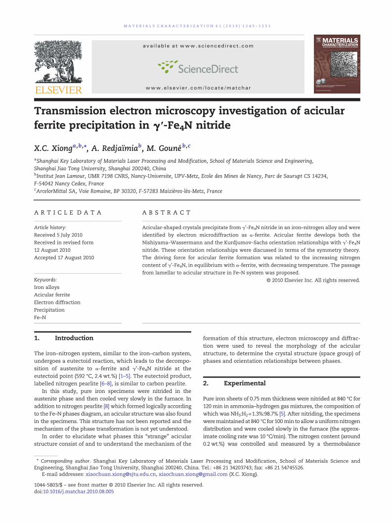
It is now necessary to explain how acicular ferrite inpearlitic γ'-Fe4N lamellae shown in Fig. 9 turns into the statewhere γ'-Fe4N lamellae become a whole block and acicularferrite grows longer, as shown in Figs. 2 and 3. A mechanismwas proposed by interpreting what was observed by Trans-mission Electron Microscopy.
A coarsened state of γ'-Fe4N lamellae was presented inFig. 10. At the middle of the micrograph, it is obvious that bycoarsening [20–23], γ'-Fe4N lamellae become 3 times thickerthan those shown in Fig. 9 and consequently acicular ferrite(marked by arrows) could grow longer (but still within γ'-Fe4Nlamellae). At the left bottom the micrograph, one can see thatthe continuous coarsening of γ'-Fe4N lamellae leads to awhole block in which pearlitic α/γ' interfaces completelydisappear. Without these pearlitic α/γ' interfaces as obstacles,acicular ferrite could then grow as long as more than 1 μm(marked by a circle). This accords well with the observationsshown in Figs. 2 and 3.
The passage form pearlitic structure to acicular structure issummarised in Fig. 11. In the Scanning Electron Micrograph(Fig. 11-a), three rectangular zones 1, 2 and 3,which reveal three
Fig. 9 – TEM micrograph showing the initial stage of theacicular ferrite precipitation (arrowed). Note that the growthof acicular ferrite is limited within the fine γ'-Fe4N lamellae.
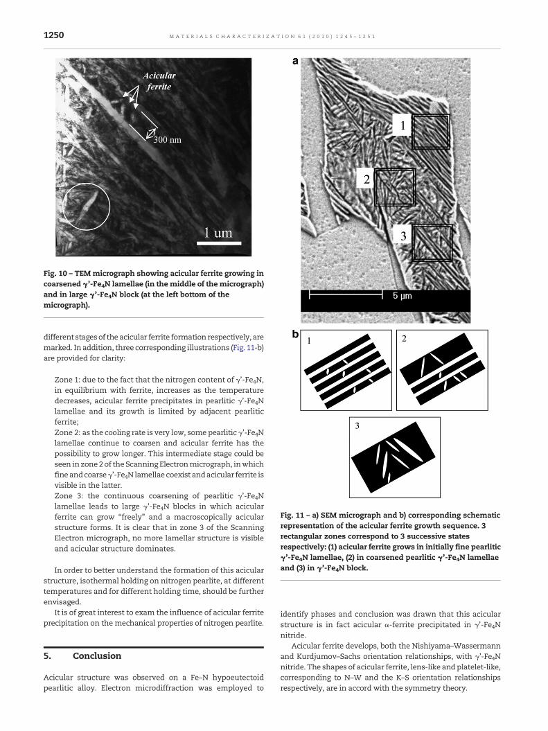
Fig. 10 – TEM micrograph showing acicular ferrite growing incoarsened γ'-Fe4N lamellae (in the middle of the micrograph)and in large γ'-Fe4N block (at the left bottom of themicrograph).
Fig. 11 – a) SEM micrograph and b) corresponding schematicrepresentation of the acicular ferrite growth sequence. 3rectangular zones correspond to 3 successive statesrespectively: (1) acicular ferrite grows in initially fine pearliticγ'-Fe4N lamellae, (2) in coarsened pearlitic γ'-Fe4N lamellaeand (3) in γ'-Fe4N block.
1250 M A T E R I A L S C H A R A C T E R I Z A T I O N 6 1 ( 2 0 1 0 ) 1 2 4 5 – 1 2 5 1
different stagesof the acicular ferrite formation respectively, aremarked. In addition, three corresponding illustrations (Fig. 11-b)are provided for clarity:
Zone 1: due to the fact that the nitrogen content of γ'-Fe4N,in equilibrium with ferrite, increases as the temperaturedecreases, acicular ferrite precipitates in pearlitic γ'-Fe4Nlamellae and its growth is limited by adjacent pearliticferrite;Zone 2: as the cooling rate is very low, some pearlitic γ'-Fe4Nlamellae continue to coarsen and acicular ferrite has thepossibility to grow longer. This intermediate stage could beseen in zone2 of theScanning Electronmicrograph, inwhichfineandcoarseγ'-Fe4N lamellae coexist andacicular ferrite isvisible in the latter.Zone 3: the continuous coarsening of pearlitic γ'-Fe4Nlamellae leads to large γ'-Fe4N blocks in which acicularferrite can grow “freely” and a macroscopically acicularstructure forms. It is clear that in zone 3 of the ScanningElectron micrograph, no more lamellar structure is visibleand acicular structure dominates.
In order to better understand the formation of this acicularstructure, isothermal holding on nitrogen pearlite, at differenttemperatures and for different holding time, should be furtherenvisaged.
It is of great interest to exam the influence of acicular ferriteprecipitation on the mechanical properties of nitrogen pearlite.
5. Conclusion
Acicular structure was observed on a Fe–N hypoeutectoidpearlitic alloy. Electron microdiffraction was employed to
identify phases and conclusion was drawn that this acicularstructure is in fact acicular α-ferrite precipitated in γ'-Fe4Nnitride.
Acicular ferrite develops, both the Nishiyama–Wassermannand Kurdjumov–Sachs orientation relationships, with γ'-Fe4Nnitride. The shapes of acicular ferrite, lens-like and platelet-like,corresponding to N–W and the K–S orientation relationshipsrespectively, are in accord with the symmetry theory.

1251M A T E R I A L S C H A R A C T E R I Z A T I O N 6 1 ( 2 0 1 0 ) 1 2 4 5 – 1 2 5 1
The passage from lamellar pearlitic structure to acicularstructure was proposed. The driving force for acicular ferriteprecipitation from γ'-Fe4N nitride was supposed to be the factthat nitrogen content of γ'-Fe4N, in equilibrium with α-ferrite,increases as the temperature decreases. Acicular ferrite growthis limited by adjacent pearlitic ferrite. The formation of acicularstructure is caused by coarsening of pearlitic γ'-Fe4N lamellaeand formation of large γ'-Fe4N nitride block.
Acknowledgement
The authors greatly acknowledge the financial support of theArcelorMittal SA.
R E F E R E N C E S
[1] HillertM, JarlM.A thermodynamicanalysisof the iron–nitrogensystem. Metall Trans A 1975;6:553–9.
[2] Ågren J. A thermodynamic analysis of the Fe–C and Fe–Nphase diagrams. Metall Trans A 1979;10:1847–52.
[3] Kunze J. Thermodynamic calculation of phase diagrams inthe iron–nitrogen system. Steel Research 1986;57:361–7.
[4] Wriedt HA, Gokcen NA, Nafziger RH. The Fe–N (iron–nitrogen)system. Bulletin of Alloy Phase Diagrams 1987;8:355–77.
[5] Kunze J. Nitrogen and carbon in iron and steel;thermodynamics, first ed., Berlin: Akademie-Verlag; 1990.
[6] Bose BN, Hawkes MF. Eutectoid transformation in alloys ofiron and nitrogen. Trans AIME 1950;188:307–16.
[7] Bell T, Farnell BC. Transformation of iron–nitrogen austeniteto pearlite. International symposium on metallurgicalchemistry-Applications in ferrousmetallurgy. Sheffield; 1971.p. 275–7.
[8] Xiong XC, Redjaïmia A, Gouné M. Pearlite inhypoeutectoid iron–nitrogen binary alloys. J Mater Sci 2009;44:632–8.
[9] Morniroli JP, Steeds JW. Microdiffraction as a tool for crystalstructure identification and determination. Ultramicroscopy1992;45:219–39.
[10] Redjaïmia A, Morniroli JP. Application of microdiffraction tocrystal structure identification. Ultramicroscopy 1994;53:305–17.
[11] Cahn JW, Kalonji G. Symmetry in solid state transformationmorphologies. International Conference on Solid-Solid PhaseTransformations. Pittsburgh: The Metallurgical Society ofAIME; 1981. p. 3–14.
[12] G.L. Kalonji, Symmetry principles in the physics of crystallineinterfaces, in, Massachusetts Institute of Technology, 1982.
[13] Jack DH, Jack KH. Invited review: carbides and nitrides insteel. Mater Sci Eng 1973;11:1–27.
[14] D. Gerardin, Study of structure faults and phasetransformations of iron carbonitrides (in French), in, InstitutNational Polytechnique de Lorraine, 1978.
[15] Somers MAJ, van der Pers NM, Schalkoord D, Mittemeijer EJ.Dependence of the lattice parameter of iron nitride Fe4N1-xon nitrogen content; accuracy of the nitrogen absorptiondatairon nitride Fe4N1-x on nitrogen content; accuracy of thenitrogen absorption data. Metall Trans A 1989;20:1533–9.
[16] De Wit L, Weber T, Custer JS, Saris FW. Thermodynamicstability of iron nitrides at temperatures below 350 °C. PhysRev Lett 1994;72:3835–8.
[17] Kooi BJ, SomersMAJ, Mittemeijer EJ. An evaluation of the Fe–Nphase diagram considering long-range order of N atoms inγ'-Fe4N1-x and ε-Fe2N1-z. Metall Mater Trans A 1996;27:1063–71.
[18] Du Marchie EH, van Voorthuysen NC, Chechenin DO Boerma.Low-temperature extension of the Lehrer diagram and theiron–nitrogen phase diagram. Metall Mater Trans A 2002;33:2593–8.
[19] Liapina T, Leineweber A, Mittemeijer EJ. Phase transformationsin iron-nitride compound layers upon low-temperatureannealing: diffusion kinetics of nitrogen in ε- and γ'-ironnitrides. Metall Mater Trans A 2006;37:319–30.
[20] Livingston JD, Cahn JW. Discontinuous coarsening of alignedeutectoids. Acta Metall 1974;22:495–503.
[21] Hillert M. The formation of pearlite. In: Zackeay VF, AaronsonHI, editors. Decomposition of austenite by diffusionalprocesses, Interscience; 1962.
[22] Chen JK, Spencer CW, Ekstrand ME, Chen G, Reynolds Jr WT.Eutectoid decomposition in Ag-Ga. Metall Mater Trans A1996;27:1683–9.
[23] Ardell AJ. Microstructural stability at elevated temperatures. JEur Ceram Soc 1999;19:2217–31.