ADDRESSING MULTIPLE CONTACT MODELLING IN REDUCERS · · 2016-11-08ADDRESSING MULTIPLE CONTACT...
14
5 th ANSA & μETA International Conference ADDRESSING MULTIPLE CONTACT MODELLING IN REDUCERS 1 A. Mihailidis * , 2 I. Neratzis, 1 E. Athanasopoulos, 1 C. Tegos 1 Aristotle University of Thessaloniki, Greece 2 BETA-CAE Systems S.A KEYWORDS – FEM, Reducers, Contact, Scripting ABSTRACT – In transmitting high torque with high ratio cycloid drives as well as Wolfrom gear drives are widely used. Cycloid reducers transfer torque through rollers, disks and cranks. Wolfrom-type gear planetary systems consist of a single sun gear, two ring gears and two sets of planetary gears, in most cases six. It is evident that in both types of reducers, torque is transmitted by multiple contacts. Besides power rating, overload capacity and transmission accuracy are important parameters that have to be considered. They are affected mainly by the elastic deformations and load distribution. FEM calculations have to be repeated at several instances in order to gain an overview of the functional behaviour of the reducer. Therefore, meshing and scripting are particularly important for the analysis. The current study presents the procedure followed in modelling and analysing two such reducers. The effect of rigidity/elasticity in specific areas of the models was investigated by building various models in 2D and 3D with different mesh densities in order to investigate the contact interactions and the integrity of the results. Scripts were used to pre-process simulation batches that animate the positions of the parts. The results were combined using also scripts that merged node output values from a series of output databases into a single file. It is concluded that with careful suggestions regarding contact interactions, mesh density and part stiffness the models can become robust in terms of solution stability and provide reliable results within limited solution time. 1. INTRODUCTION The modelling process of cycloid drives involves the adequate representation of the CAD geometry. Depending on the specific type of the reducer, the cycloid profile can be any curve belonging to the mathematical family of trochoid curves. The design of any trochoid curve is the trace produced by a point on a circle rolling inside or outside a second circle. The ideal trochoid is simultaneously in contact with every cylindrical profile on the housing. In comparison to the spur gears commonly used in reducers, cycloid drives have at any given working position a multiplicity of contacting regions, with a maximum span of 180 degrees of the disk circumference, capable of transferring torque. The actual load distribution is determined by the profile accuracy and the stiffness of the cycloid disk. In typical cycloid drives the actual area sharing the load is much less than 180 degrees and can even be limited to 90 degrees. Wolfrom drives are composite planetary gear trains that are composed of two reduced simple planetary gear trains having the same carrier. The planets of each stage may have the same or different teeth numbers. The number of flanks in contact at any instance can vary from 6 to even 12 depending on the gear geometry. The reduction ratio of a cycloid drive is determined by the number of cylindrical profiles and the corresponding lobes of the trochoid curve. High reduction ratios can be achieved and the number of contacts increases in direct proportion. A secondary feature, that increases the number of contacts, is the existence of a secondary or third disk, used for counterbalancing and increasing the contact surface width while maintaining each individual disk thin in order to minimize angling of the contact lines. Wolfrom drives reduction ratio is based on the ratio of teeth difference between the two ring gears. The number of contacts depends on the number of planets and the gear geometry.
-
Upload
phungthien -
Category
Documents
-
view
215 -
download
1
Transcript of ADDRESSING MULTIPLE CONTACT MODELLING IN REDUCERS · · 2016-11-08ADDRESSING MULTIPLE CONTACT...
5th
ANSA & μETA International Conference
ADDRESSING MULTIPLE CONTACT MODELLING IN REDUCERS 1A. Mihailidis *, 2I. Neratzis, 1E. Athanasopoulos, 1C. Tegos 1 Aristotle University of Thessaloniki, Greece 2 BETA-CAE Systems S.A KEYWORDS – FEM, Reducers, Contact, Scripting ABSTRACT – In transmitting high torque with high ratio cycloid drives as well as Wolfrom gear drives are widely used. Cycloid reducers transfer torque through rollers, disks and cranks. Wolfrom-type gear planetary systems consist of a single sun gear, two ring gears and two sets of planetary gears, in most cases six. It is evident that in both types of reducers, torque is transmitted by multiple contacts. Besides power rating, overload capacity and transmission accuracy are important parameters that have to be considered. They are affected mainly by the elastic deformations and load distribution. FEM calculations have to be repeated at several instances in order to gain an overview of the functional behaviour of the reducer. Therefore, meshing and scripting are particularly important for the analysis. The current study presents the procedure followed in modelling and analysing two such reducers. The effect of rigidity/elasticity in specific areas of the models was investigated by building various models in 2D and 3D with different mesh densities in order to investigate the contact interactions and the integrity of the results. Scripts were used to pre-process simulation batches that animate the positions of the parts. The results were combined using also scripts that merged node output values from a series of output databases into a single file. It is concluded that with careful suggestions regarding contact interactions, mesh density and part stiffness the models can become robust in terms of solution stability and provide reliable results within limited solution time. 1. INTRODUCTION The modelling process of cycloid drives involves the adequate representation of the CAD geometry. Depending on the specific type of the reducer, the cycloid profile can be any curve belonging to the mathematical family of trochoid curves. The design of any trochoid curve is the trace produced by a point on a circle rolling inside or outside a second circle. The ideal trochoid is simultaneously in contact with every cylindrical profile on the housing. In comparison to the spur gears commonly used in reducers, cycloid drives have at any given working position a multiplicity of contacting regions, with a maximum span of 180 degrees of the disk circumference, capable of transferring torque. The actual load distribution is determined by the profile accuracy and the stiffness of the cycloid disk. In typical cycloid drives the actual area sharing the load is much less than 180 degrees and can even be limited to 90 degrees. Wolfrom drives are composite planetary gear trains that are composed of two reduced simple planetary gear trains having the same carrier. The planets of each stage may have the same or different teeth numbers. The number of flanks in contact at any instance can vary from 6 to even 12 depending on the gear geometry. The reduction ratio of a cycloid drive is determined by the number of cylindrical profiles and the corresponding lobes of the trochoid curve. High reduction ratios can be achieved and the number of contacts increases in direct proportion. A secondary feature, that increases the number of contacts, is the existence of a secondary or third disk, used for counterbalancing and increasing the contact surface width while maintaining each individual disk thin in order to minimize angling of the contact lines. Wolfrom drives reduction ratio is based on the ratio of teeth difference between the two ring gears. The number of contacts depends on the number of planets and the gear geometry.
5th
ANSA & μETA International Conference
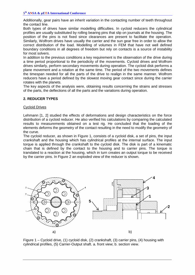
Additionally, gear pairs have an inherit variation in the contacting number of teeth throughout the contact line. Both types of drives have similar modelling difficulties. In cycloid reducers the cylindrical profiles are usually substituted by rolling bearing pins that slip on journals at the housing. The position of the pins is not fixed since clearances are present to facilitate the operation. Similarly, Wolfrom drives have usually the carrier and the sun gear free in order to allow the correct distribution of the load. Modelling of volumes in FEM that have not well defined boundary conditions in all degrees of freedom but rely on contacts is a source of instability for most solvers. In addition to the previous conditions a key requirement is the observation of the drive during a time period proportional to the periodicity of the movements. Cycloid drives and Wolfrom drives similarly, perform secondary movements during operation. The cycloid disk performs a plane movement and a rotation at the same time. The period of the two movements defines the timespan needed for all the parts of the drive to realign in the same manner. Wolfrom reducers have a period defined by the slowest moving gear contact since during the carrier rotates with the planets. The key aspects of the analysis were, obtaining results concerning the strains and stresses of the parts, the deflections of all the parts and the variations during operation. 2. REDUCER TYPES Cycloid Drives Lehmann [1, 2] studied the effects of deformations and design characteristics on the force distribution of a cycloid reducer. He also verified his calculations by comparing the calculated results to measurements obtained on a test rig. He concluded that the loading of the elements deforms the geometry of the contact resulting in the need to modify the geometry of the curve. The cycloid reducer, as shown in Figure 1, consists of a cycloid disk, a set of pins, the input crankshaft and the housing which has cylindrical profiles at the internal surface. The input torque is applied through the crankshaft to the cycloid disk. The disk is part of a kinematic chain that is defined by the contact to the housing and to carrier pins. The torque is translated to a reaction at the housing, which in turn creates an output torque to be received by the carrier pins. In Figure 2 an exploded view of the reducer is shown.
a) b) Figure 1 – Cycloid drive, (1) cycloid disk, (2) crankshaft, (3) carrier pins, (4) housing with cylindrical profiles, (5) Carrier-Output shaft. a. front view; b. section view.
4
3
1
2 5
5th
ANSA & μETA International Conference
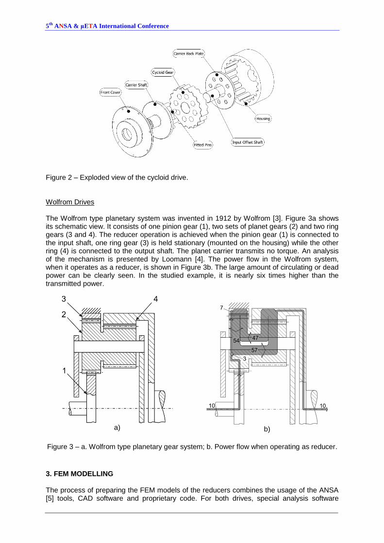
Figure 2 – Exploded view of the cycloid drive. Wolfrom Drives The Wolfrom type planetary system was invented in 1912 by Wolfrom [3]. Figure 3a shows its schematic view. It consists of one pinion gear (1), two sets of planet gears (2) and two ring gears (3 and 4). The reducer operation is achieved when the pinion gear (1) is connected to the input shaft, one ring gear (3) is held stationary (mounted on the housing) while the other ring (4) is connected to the output shaft. The planet carrier transmits no torque. An analysis of the mechanism is presented by Loomann [4]. The power flow in the Wolfrom system, when it operates as a reducer, is shown in Figure 3b. The large amount of circulating or dead power can be clearly seen. In the studied example, it is nearly six times higher than the transmitted power.
a)
b)
Figure 3 – a. Wolfrom type planetary gear system; b. Power flow when operating as reducer.
3. FEM MODELLING The process of preparing the FEM models of the reducers combines the usage of the ANSA [5] tools, CAD software and proprietary code. For both drives, special analysis software
5th
ANSA & μETA International Conference
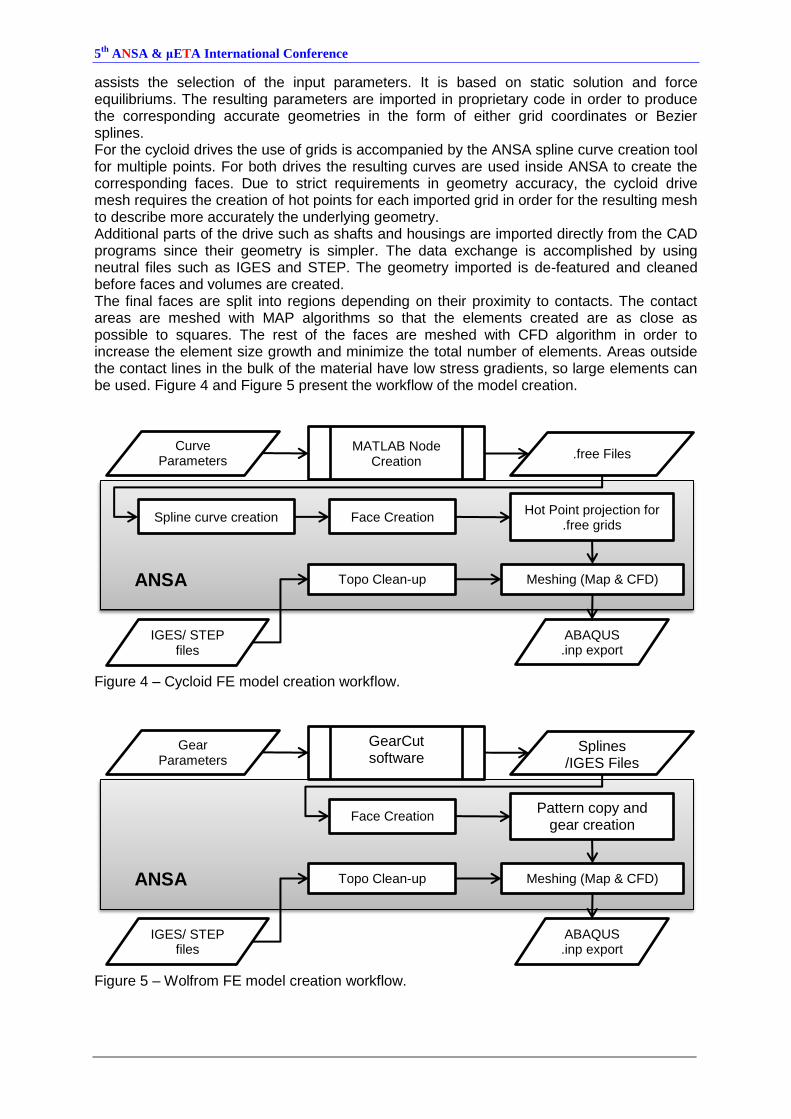
assists the selection of the input parameters. It is based on static solution and force equilibriums. The resulting parameters are imported in proprietary code in order to produce the corresponding accurate geometries in the form of either grid coordinates or Bezier splines. For the cycloid drives the use of grids is accompanied by the ANSA spline curve creation tool for multiple points. For both drives the resulting curves are used inside ANSA to create the corresponding faces. Due to strict requirements in geometry accuracy, the cycloid drive mesh requires the creation of hot points for each imported grid in order for the resulting mesh to describe more accurately the underlying geometry. Additional parts of the drive such as shafts and housings are imported directly from the CAD programs since their geometry is simpler. The data exchange is accomplished by using neutral files such as IGES and STEP. The geometry imported is de-featured and cleaned before faces and volumes are created. The final faces are split into regions depending on their proximity to contacts. The contact areas are meshed with MAP algorithms so that the elements created are as close as possible to squares. The rest of the faces are meshed with CFD algorithm in order to increase the element size growth and minimize the total number of elements. Areas outside the contact lines in the bulk of the material have low stress gradients, so large elements can be used. Figure 4 and Figure 5 present the workflow of the model creation.
Figure 4 – Cycloid FE model creation workflow.
Figure 5 – Wolfrom FE model creation workflow.
MATLAB Node Creation
Curve Parameters
.free Files
Spline curve creation Face Creation Hot Point projection for
.free grids
Meshing (Map & CFD)
IGES/ STEP files
Topo Clean-up ANSA
ABAQUS .inp export
GearCut software
Gear Parameters
Splines /IGES Files
Face Creation Pattern copy and
gear creation
Meshing (Map & CFD)
IGES/ STEP files
Topo Clean-up ANSA
ABAQUS .inp export
5th
ANSA & μETA International Conference
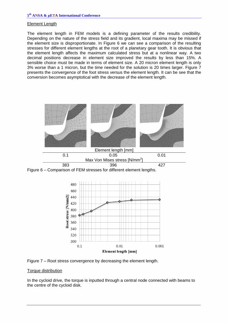
Element Length The element length in FEM models is a defining parameter of the results credibility. Depending on the nature of the stress field and its gradient, local maxima may be missed if the element size is disproportionate. In Figure 6 we can see a comparison of the resulting stresses for different element lengths at the root of a planetary gear tooth. It is obvious that the element length affects the maximum calculated stress but at a nonlinear way. A two decimal positions decrease in element size improved the results by less than 15%. A sensible choice must be made in terms of element size. A 20 micron element length is only 3% worse than a 1 micron, but the time needed for the solution is 20 times larger. Figure 7 presents the convergence of the foot stress versus the element length. It can be see that the conversion becomes asymptotical with the decrease of the element length.
Element length [mm]
0.1 0.05 0.01 Max Von Mises stress [N/mm2]
383 396 427 Figure 6 – Comparison of FEM stresses for different element lengths.
Figure 7 – Root stress convergence by decreasing the element length. Torque distribution In the cycloid drive, the torque is inputted through a central node connected with beams to the centre of the cycloid disk.
5th
ANSA & μETA International Conference
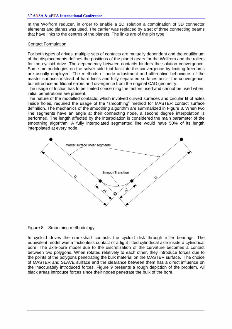
In the Wolfrom reducer, in order to enable a 2D solution a combination of 3D connector elements and planes was used. The carrier was replaced by a set of three connecting beams that have links to the centres of the planets. The links are of the pin type Contact Formulation For both types of drives, multiple sets of contacts are mutually dependent and the equilibrium of the displacements defines the positions of the planet gears for the Wolfrom and the rollers for the cycloid drive. The dependency between contacts hinders the solution convergence. Some methodologies on the solver side that facilitate the convergence by limiting freedoms are usually employed. The methods of node adjustment and alternative behaviours of the master surfaces instead of hard limits and fully separated surfaces assist the convergence, but introduce additional errors and divergence from the original CAD geometry. The usage of friction has to be limited concerning the factors used and cannot be used when initial penetrations are present. The nature of the modelled contacts, which involved curved surfaces and circular fit of axles inside holes, required the usage of the “smoothing” method for MASTER contact surface definition. The mechanics of the smoothing algorithm are summarized in Figure 8. When two line segments have an angle at their connecting node, a second degree interpolation is performed. The length affected by the interpolation is considered the main parameter of the smoothing algorithm. A fully interpolated segmented line would have 50% of its length interpolated at every node.
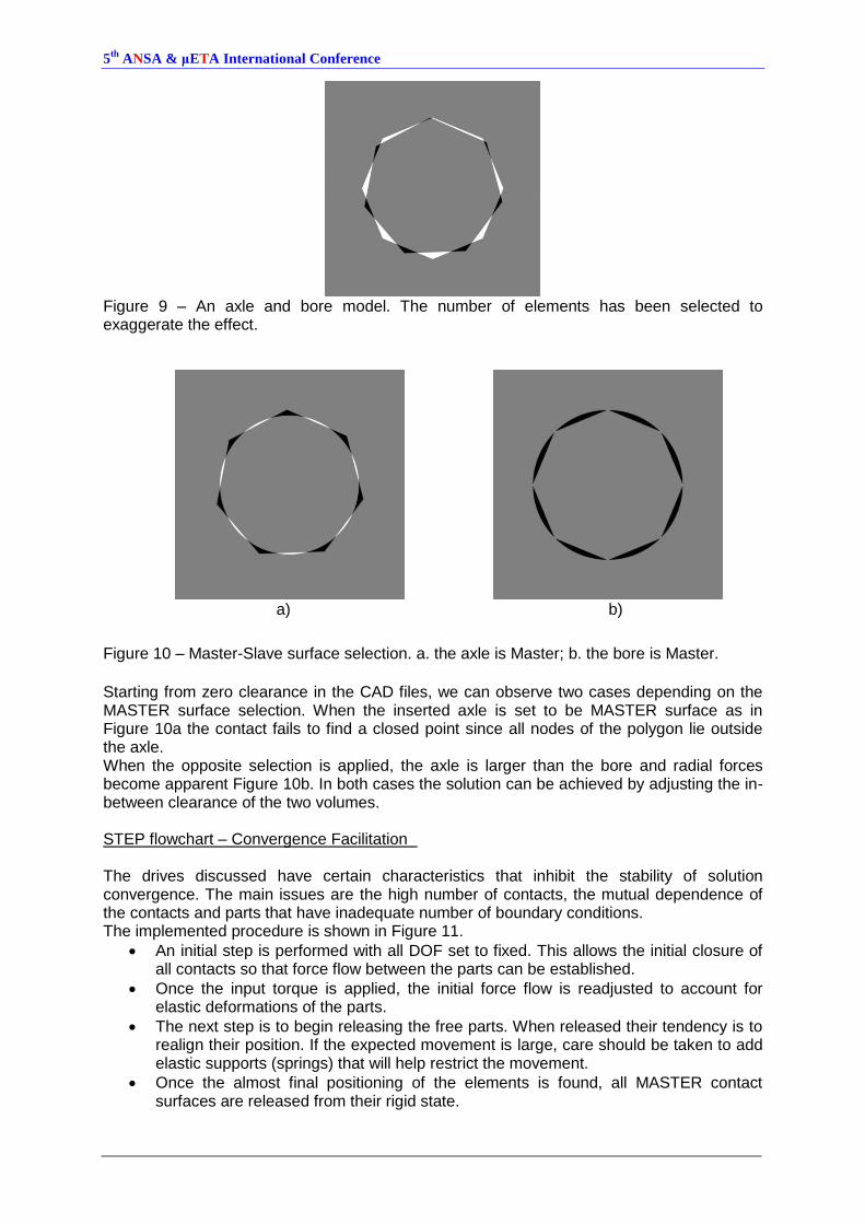
Figure 8 – Smoothing methodology. In cycloid drives the crankshaft contacts the cycloid disk through roller bearings. The equivalent model was a frictionless contact of a tight fitted cylindrical axle inside a cylindrical bore. The axle-bore model due to the discretization of the curvature becomes a contact between two polygons. When rotated relatively to each other, they introduce forces due to the points of the polygons penetrating the bulk material on the MASTER surface. The choice of MASTER and SLAVE surface and the clearance between them has a direct influence on the inaccurately introduced forces. Figure 9 presents a rough depiction of the problem. All black areas introduce forces since their nodes penetrate the bulk of the bore.
5th
ANSA & μETA International Conference
Figure 9 – An axle and bore model. The number of elements has been selected to exaggerate the effect.
a)
b)
Figure 10 – Master-Slave surface selection. a. the axle is Master; b. the bore is Master.
Starting from zero clearance in the CAD files, we can observe two cases depending on the MASTER surface selection. When the inserted axle is set to be MASTER surface as in Figure 10a the contact fails to find a closed point since all nodes of the polygon lie outside the axle. When the opposite selection is applied, the axle is larger than the bore and radial forces become apparent Figure 10b. In both cases the solution can be achieved by adjusting the in-between clearance of the two volumes. STEP flowchart – Convergence Facilitation The drives discussed have certain characteristics that inhibit the stability of solution convergence. The main issues are the high number of contacts, the mutual dependence of the contacts and parts that have inadequate number of boundary conditions. The implemented procedure is shown in Figure 11.
An initial step is performed with all DOF set to fixed. This allows the initial closure of all contacts so that force flow between the parts can be established.
Once the input torque is applied, the initial force flow is readjusted to account for elastic deformations of the parts.
The next step is to begin releasing the free parts. When released their tendency is to realign their position. If the expected movement is large, care should be taken to add elastic supports (springs) that will help restrict the movement.
Once the almost final positioning of the elements is found, all MASTER contact surfaces are released from their rigid state.
5th
ANSA & μETA International Conference
A final step is performed to remove the spring supports if present and any additional supports and boundaries. In some cases an addition of a small friction parameter is helpful to speed up the convergence.
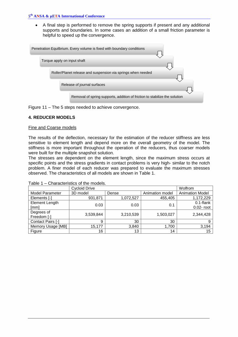
Figure 11 – The 5 steps needed to achieve convergence. 4. REDUCER MODELS Fine and Coarse models The results of the deflection, necessary for the estimation of the reducer stiffness are less sensitive to element length and depend more on the overall geometry of the model. The stiffness is more important throughout the operation of the reducers, thus coarser models were built for the multiple snapshot solution. The stresses are dependent on the element length, since the maximum stress occurs at specific points and the stress gradients in contact problems is very high- similar to the notch problem. A finer model of each reducer was prepared to evaluate the maximum stresses observed. The characteristics of all models are shown in Table 1. Table 1 – Characteristics of the models. Cycloid Drive Wolfrom
Model Parameter 3D model Dense Animation model Animation Model
Elements [-] 931,871 1,072,527 455,405 1,172,229
Element Length [mm]
0.03 0.03 0.1 0.1-flank
0.02- root
Degrees of Freedom [-]
3,539,844 3,210,539 1,503,027 2,344,428
Contact Pairs [-] 9 30 30 9
Memory Usage [MB] 15,177 3,840 1,700 3,194
Figure 16 13 14 15
Penetration Equilbrium. Every volume is fixed with boundary conditions
Torque apply on input shaft
Roller/Planet release and suspension via springs when needed
Release of journal surfaces
Removal of spring supports, addition of friction to stabilize the solution
5th
ANSA & μETA International Conference
a) b)
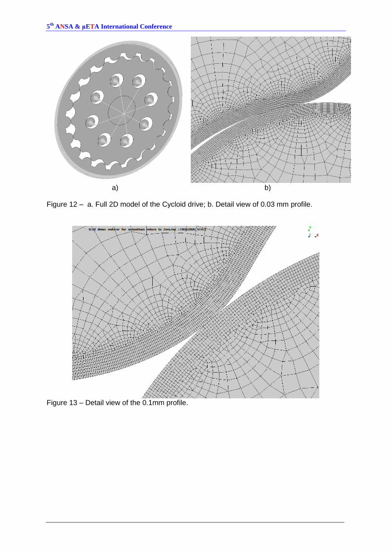
Figure 12 – a. Full 2D model of the Cycloid drive; b. Detail view of 0.03 mm profile.
Figure 13 – Detail view of the 0.1mm profile.
5th
ANSA & μETA International Conference
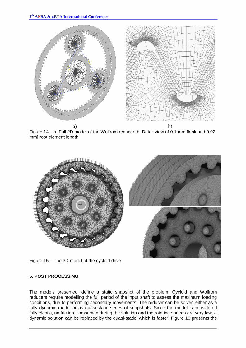
a) b) Figure 14 – a. Full 2D model of the Wolfrom reducer; b. Detail view of 0.1 mm flank and 0.02 mm] root element length.
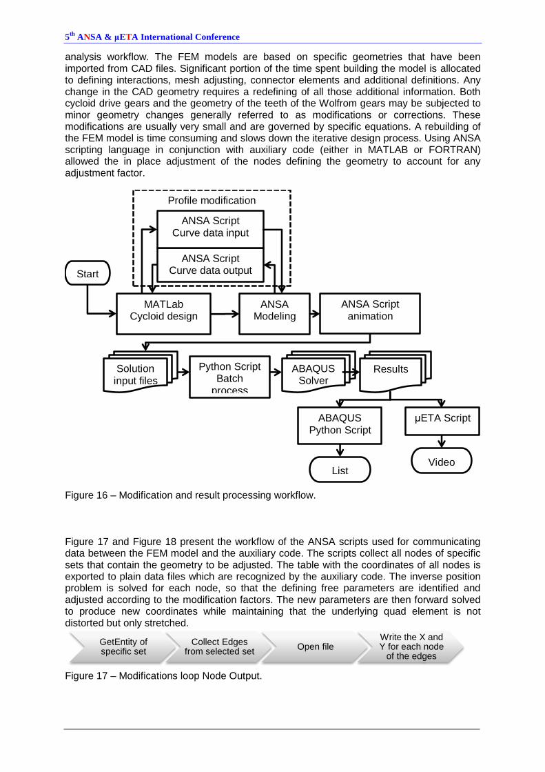
Figure 15 – The 3D model of the cycloid drive. 5. POST PROCESSING The models presented, define a static snapshot of the problem. Cycloid and Wolfrom reducers require modelling the full period of the input shaft to assess the maximum loading conditions, due to performing secondary movements. The reducer can be solved either as a fully dynamic model or as quasi-static series of snapshots. Since the model is considered fully elastic, no friction is assumed during the solution and the rotating speeds are very low, a dynamic solution can be replaced by the quasi-static, which is faster. Figure 16 presents the
5th
ANSA & μETA International Conference
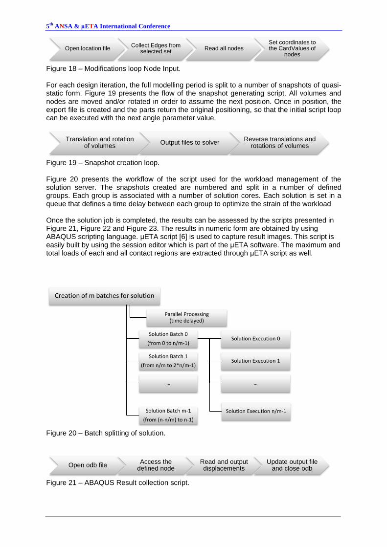
analysis workflow. The FEM models are based on specific geometries that have been imported from CAD files. Significant portion of the time spent building the model is allocated to defining interactions, mesh adjusting, connector elements and additional definitions. Any change in the CAD geometry requires a redefining of all those additional information. Both cycloid drive gears and the geometry of the teeth of the Wolfrom gears may be subjected to minor geometry changes generally referred to as modifications or corrections. These modifications are usually very small and are governed by specific equations. A rebuilding of the FEM model is time consuming and slows down the iterative design process. Using ANSA scripting language in conjunction with auxiliary code (either in MATLAB or FORTRAN) allowed the in place adjustment of the nodes defining the geometry to account for any adjustment factor.
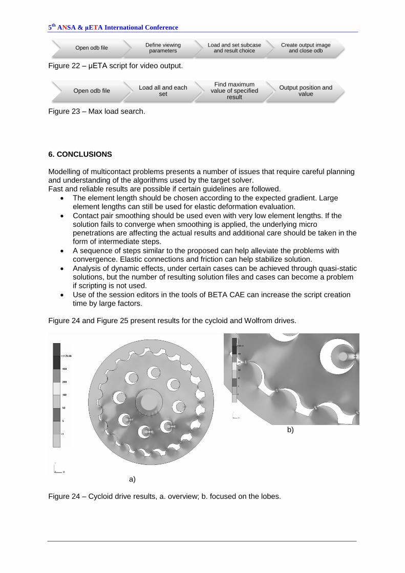
Figure 16 – Modification and result processing workflow. Figure 17 and Figure 18 present the workflow of the ANSA scripts used for communicating data between the FEM model and the auxiliary code. The scripts collect all nodes of specific sets that contain the geometry to be adjusted. The table with the coordinates of all nodes is exported to plain data files which are recognized by the auxiliary code. The inverse position problem is solved for each node, so that the defining free parameters are identified and adjusted according to the modification factors. The new parameters are then forward solved to produce new coordinates while maintaining that the underlying quad element is not distorted but only stretched.
Figure 17 – Modifications loop Node Output.
Profile modification
MATLab Cycloid design
ANSA Modeling
ANSA Script animation
Solution input files
ABAQUS Solver
ABAQUS Python Script
Results
List
ANSA Script Curve data output
ANSA Script Curve data input
Python Script Batch
process
Start
μETA Script
Video
GetEntity of specific set
Collect Edges from selected set
Open file Write the X and Y for each node
of the edges
5th
ANSA & μETA International Conference
Figure 18 – Modifications loop Node Input. For each design iteration, the full modelling period is split to a number of snapshots of quasi-static form. Figure 19 presents the flow of the snapshot generating script. All volumes and nodes are moved and/or rotated in order to assume the next position. Once in position, the export file is created and the parts return the original positioning, so that the initial script loop can be executed with the next angle parameter value.
Figure 19 – Snapshot creation loop. Figure 20 presents the workflow of the script used for the workload management of the solution server. The snapshots created are numbered and split in a number of defined groups. Each group is associated with a number of solution cores. Each solution is set in a queue that defines a time delay between each group to optimize the strain of the workload Once the solution job is completed, the results can be assessed by the scripts presented in Figure 21, Figure 22 and Figure 23. The results in numeric form are obtained by using ABAQUS scripting language. μETA script [6] is used to capture result images. This script is easily built by using the session editor which is part of the μETA software. The maximum and total loads of each and all contact regions are extracted through μETA script as well.
Figure 20 – Batch splitting of solution.
Figure 21 – ABAQUS Result collection script.
Open location file Collect Edges from
selected set Read all nodes
Set coordinates to the CardValues of
nodes
Translation and rotation of volumes
Output files to solver Reverse translations and
rotations of volumes
Creation of m batches for solution
Solution Batch 0
(from 0 to n/m-1) Solution Execution 0
Solution Execution 1
…
Solution Execution n/m-1
Solution Batch 1
(from n/m to 2*n/m-1)
…
Parallel Processing (time delayed)
Solution Batch m-1
(from (n-n/m) to n-1)
Open odb file Access the
defined node Read and output displacements
Update output file and close odb
5th
ANSA & μETA International Conference
Figure 22 – μΕΤΑ script for video output.
Figure 23 – Max load search. 6. CONCLUSIONS Modelling of multicontact problems presents a number of issues that require careful planning and understanding of the algorithms used by the target solver. Fast and reliable results are possible if certain guidelines are followed.
The element length should be chosen according to the expected gradient. Large element lengths can still be used for elastic deformation evaluation.
Contact pair smoothing should be used even with very low element lengths. If the solution fails to converge when smoothing is applied, the underlying micro penetrations are affecting the actual results and additional care should be taken in the form of intermediate steps.
A sequence of steps similar to the proposed can help alleviate the problems with convergence. Elastic connections and friction can help stabilize solution.
Analysis of dynamic effects, under certain cases can be achieved through quasi-static solutions, but the number of resulting solution files and cases can become a problem if scripting is not used.
Use of the session editors in the tools of BETA CAE can increase the script creation time by large factors.
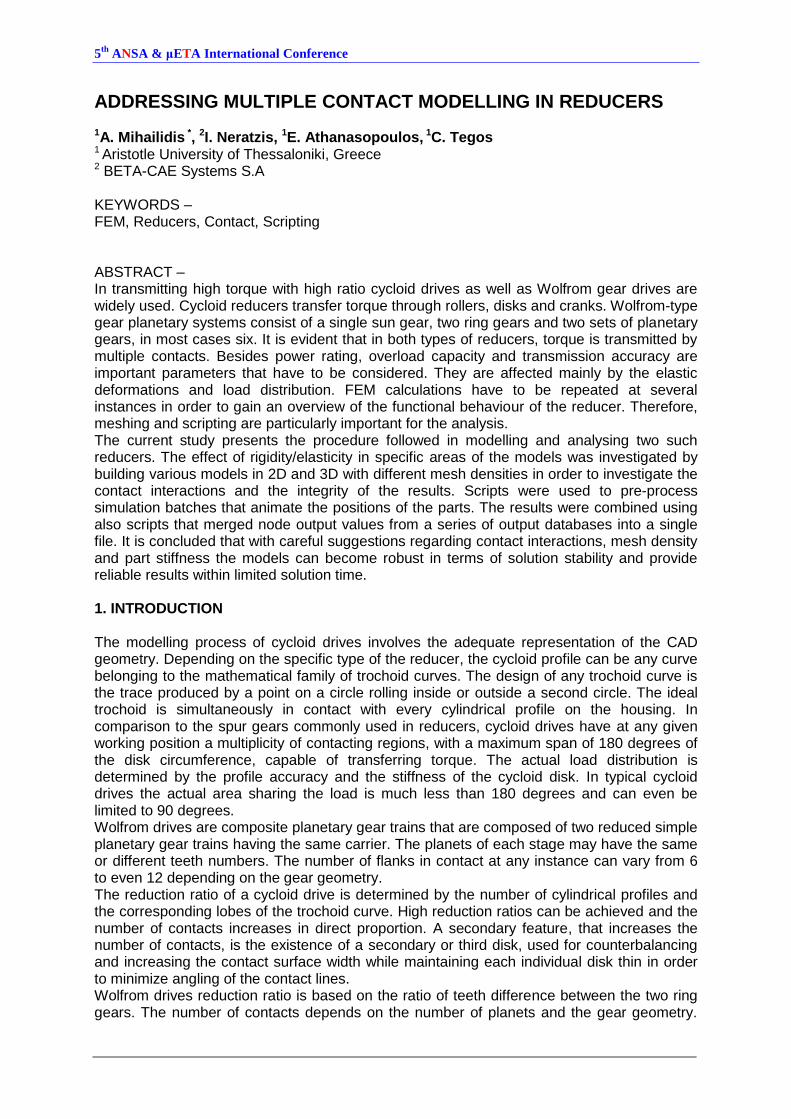
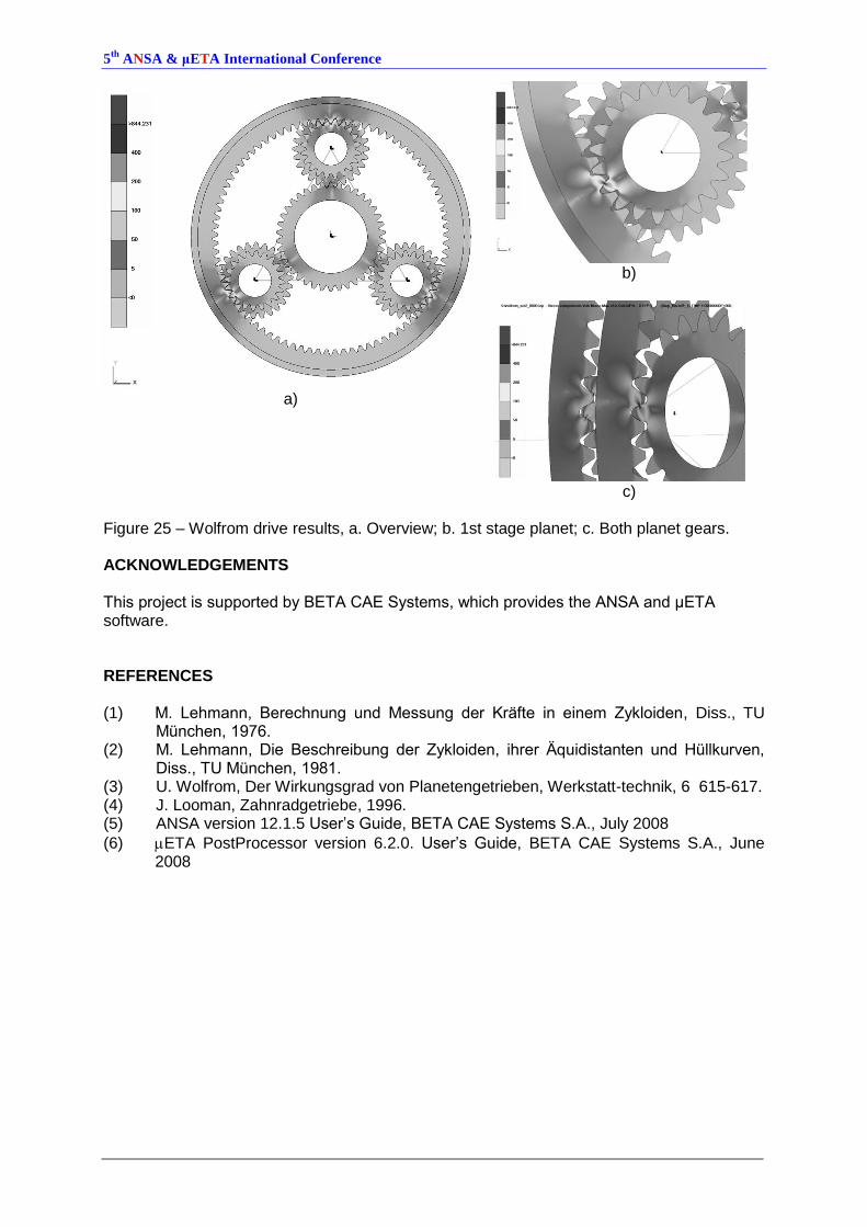
Figure 24 and Figure 25 present results for the cycloid and Wolfrom drives.
a)
b)
Figure 24 – Cycloid drive results, a. overview; b. focused on the lobes.
Open odb file Define viewing
parameters Load and set subcase
and result choice Create output image
and close odb
Open odb file Load all and each
set
Find maximum value of specified
result
Output position and value
5th
ANSA & μETA International Conference
a)
b)
c)
Figure 25 – Wolfrom drive results, a. Overview; b. 1st stage planet; c. Both planet gears. ACKNOWLEDGEMENTS This project is supported by BETA CAE Systems, which provides the ANSA and μETA software. REFERENCES (1) M. Lehmann, Berechnung und Messung der Kräfte in einem Zykloiden, Diss., TU
München, 1976. (2) M. Lehmann, Die Beschreibung der Zykloiden, ihrer Äquidistanten und Hüllkurven,
Diss., TU München, 1981. (3) U. Wolfrom, Der Wirkungsgrad von Planetengetrieben, Werkstatt-technik, 6 615-617. (4) J. Looman, Zahnradgetriebe, 1996. (5) ANSA version 12.1.5 User’s Guide, BETA CAE Systems S.A., July 2008
(6) ETA PostProcessor version 6.2.0. User’s Guide, BETA CAE Systems S.A., June 2008