Activity 2: Opto Receiver
12
Wireless Transmission: Your TV Remote Pilot Module Spring 2008 (Updated 2/7/08) 11 Activity 2: Opto Receiver Time Required: 45 minutes Materials List Group Size: 2 Each pair needs: One each of: • One Activity 2 bag containing: o Two 10 μF Electrolytic Capacitors o 47 μF Electrolytic Capacitor o 100 μF Electrolytic Capacitor o Phototransistor o LM 386 Integrated Circuit • These items are provided in a separate bag, but will be placed back in Activity 2 bag after activity for use in subsequent years: o 24 kΩ Resistor (Red, Yellow, Orange) o SPK: Audio Speaker o 9 V Battery o Five 2” Jumper Wires • Battery Snap (in bag with breadboard) • Breadboard To share between every two groups: • Multimeter • Tape Measure • Pliers To share with the class: • TV Remote Student Handouts • Activity 2: Opto Receiver Learning Objectives After this activity, students should be able to: • Identify an LM 386 Integrated Circuit (IC) audio amplifier and describe what its purpose in the circuit is. • Identify the polarity of an electrolytic capacitor. • Identify a phototransistor and identify what its purpose in the circuit is. • Identify an audio speaker and identify what its purpose in the circuit is. Introduction Last time, you built a simple circuit on a breadboard. Engineers use breadboards to make prototypes of circuits to make sure they work before they print them on circuit boards. This time, we will begin working on a more complex circuit that receives an infrared (IR) signal and plays sound based on the IR signal strength. This is similar to
Transcript of Activity 2: Opto Receiver
Wireless Transmission: Your TV Remote
Pilot Module Spring 2008 (Updated 2/7/08) 11
Activity 2: Opto Receiver Time Required: 45 minutes Materials List Group Size: 2 Each pair needs: One each of:
• One Activity 2 bag containing: o Two 10 μF Electrolytic Capacitors o 47 μF Electrolytic Capacitor o 100 μF Electrolytic Capacitor o Phototransistor o LM 386 Integrated Circuit
• These items are provided in a separate bag, but will be placed back in Activity 2 bag after activity for use in subsequent years:
o 24 kΩ Resistor (Red, Yellow, Orange) o SPK: Audio Speaker o 9 V Battery o Five 2” Jumper Wires
• Battery Snap (in bag with breadboard) • Breadboard
To share between every two groups: • Multimeter • Tape Measure • Pliers
To share with the class: • TV Remote
Student Handouts • Activity 2: Opto Receiver
Learning Objectives After this activity, students should be able to:
• Identify an LM 386 Integrated Circuit (IC) audio amplifier and describe what its purpose in the circuit is.
• Identify the polarity of an electrolytic capacitor. • Identify a phototransistor and identify what its purpose in the circuit is. • Identify an audio speaker and identify what its purpose in the circuit is.
Introduction Last time, you built a simple circuit on a breadboard. Engineers use breadboards to make prototypes of circuits to make sure they work before they print them on circuit boards. This time, we will begin working on a more complex circuit that receives an infrared (IR) signal and plays sound based on the IR signal strength. This is similar to
Wireless Transmission: Your TV Remote
Pilot Module Spring 2008 (Updated 2/7/08) 12
the receiver in your TV except that the TV interprets the signal and changes the volume, changes the channel, or does something else that you can find on a TV remote. [Show the students an example of a TV remote.] At the end of the day today, you will test your circuit to see if it can receive a signal from a TV remote. You will use this same circuit over the next few sessions to receive different IR signals. Vocabulary
Word Definition Opto Short for optical. Relates to light. Capacitor A device that stabilizes voltage. Phototransistor A device that converts light into electricity. Integrated Circuit (IC) A small, solid device with many electronic components inside. Infrared (IR) A form of light that the human eye cannot see; invisible light Opto Receiver Circuit that takes light signals as the input and converts the light
into an electrical signal. Troubleshooting This is the process an engineer uses when trying to determine
why something he/she has built is not working. Schematic A diagram of a circuit used by electrical engineers.
Procedure Instructor Preparation: (Time = 10 minutes) Check each multimeter and 9 V battery by turning the knob of the multimeter to the 20 V DC setting and touching the probes to the battery terminals. The multimeter should read more than 8.7 V. If the multimeter reads less than 8.7 V, try a second meter. If that meter still reads less than 8.7 V, try a new battery. During the Activity:
1) Split students into groups of two. 2) Let the students know that there are many small parts in these kits. They should
be careful while using them not to lose any. While working on this project, the students should work with their partner while not disturbing other groups. Students should also be warned to be careful not to disturb the components of other groups. Do not knock another group’s table.
3) Pass out electronic components. Tell the students not to connect the battery to anything until they are told to do so!
4) Walk around and help the students as they work through the activity. a. If the opto receivers do not produce sound when the TV remote is fired at the
phototransistor, have the students remove one of the battery leads from their breadboard and follow the troubleshooting procedure in the student handout.
b. Help the students check to make sure their circuits are built correctly.
Wireless Transmission: Your TV Remote
Pilot Module Spring 2008 (Updated 2/7/08) 13
c. If the battery leads are hard to get into the breadboards, try twisting the strands of the wires to form a firmer end of the wire.
5) At the end of the activity, ask the students to put the components back in their original bags.
6) Collect the components from the students. The batteries go back in the boxes to keep the contacts from touch something metal and short circuiting.
Processing and Activity Closure: As the activity is finishing up, before you have cleaned up, ask the students to describe the sound that is made when the TV remote is fired at the photo transistor in their opto receiver circuits. Ask them why they think it sounds like this. What happens when you push a button on the TV remote and fire it at a TV? You can tell them the signal is carried by infrared light which is invisible to the human eye. The signal is made by turning the invisible infrared light on and off in a regular pattern. The photo transistor senses the light turning on and off and turns the IR energy into electrical energy. A similar receiver in your TV would take that electrical energy and change the volume or the channel. In this case, the opto receiver uses the electrical energy to drive the speaker, and we hear the beeping sound produced by that signal. Next time, we will build a circuit that is similar to the remote in that it will transmit an IR signal to the receiver that we will be able to hear and change. During the following session, we will build a transmitter that will transmit music wirelessly using infrared light. Additional Resources Chaney Electronics – BBK-3 44 in 1 Communications and Opto Lab Kit http://www.kitsuse.net For more information about capacitors: http://electronics.howstuffworks.com/capacitor.htm For more information about how speakers work: http://electronics.howstuffworks.com/speaker.htm Assessment
1) On a separate sheet of paper, please indicate what percentage of the students’ opto receivers worked by the end of class. This will be used to assess whether or not students understand how a breadboard works. The students should understand which rows and columns are connected on the board. They will need to understand this in order to complete the circuit.
2) Collect or copy page 22 of the student handout. Exploration 1 will be used to determine if the students understand that a photo transistor converts light into electrical energy.
References Chaney Electronics, 44 in 1 Communications and Opto Lab Manual, 1997.

Wireless Transmission: Your TV Remote
Pilot Module Spring 2008 (Updated 2/7/08) 14
Authors: Dr. Gary A. Ybarra, Dr. Paul A. Klenk Contributors: Dr. Martin Brooke, Heather Wake, Xin Cai, Arnak Aleksanyan, Department of Electrical and Computer Engineering, Duke University. Copyright: Engineering K-Ph.D. Program, Pratt School of Engineering, Duke University
Wireless Transmission: Your TV Remote
Pilot Module Spring 2008 (Updated 2/7/08) 15
Activity 2: Opto Receiver Student Handout Name: ________________________ Date: __________ In this activity you will build an opto (optical) receiver that converts light signals into sound. At the end of this activity, you will test your opto receiver by pointing a TV remote at the input and hearing the signal that your TV responds to when you hit a button on the remote. When you finish building this circuit, you will not take it apart, because you will be using it in Activities 3 and 4. The first thing to do is to identify the parts you will need. Parts List R1: 24 kΩ Resistor (Red, Yellow, Orange) C1: 10 μF Electrolytic Capacitor C2: 47 μF Electrolytic Capacitor C3: 10 μF Electrolytic Capacitor C4: 100 μF Electrolytic Capacitor Q1: Phototransistor IC1: LM 386 Integrated Circuit SPK: Audio Speaker 9 V Battery Battery Snap Breadboard 2” Jumper Wires You know how to identify the 24 kΩ Resistor from Activity 1 by using the resistor color code.
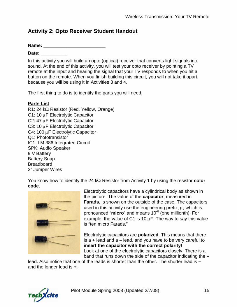
Electrolytic capacitors have a cylindrical body as shown in the picture. The value of the capacitor, measured in Farads, is shown on the outside of the case. The capacitors used in this activity use the engineering prefix, μ, which is pronounced “micro” and means 10-6 (one millionth). For example, the value of C1 is 10 μF. The way to say this value is “ten micro Farads.” Electrolytic capacitors are polarized. This means that there is a + lead and a – lead, and you have to be very careful to insert the capacitor with the correct polarity! Look at one of the electrolytic capacitors closely. There is a band that runs down the side of the capacitor indicating the –
lead. Also notice that one of the leads is shorter than the other. The shorter lead is – and the longer lead is +.
Wireless Transmission: Your TV Remote
Pilot Module Spring 2008 (Updated 2/7/08) 16
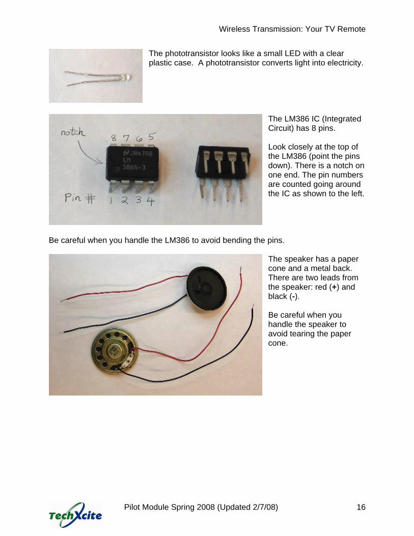
The phototransistor looks like a small LED with a clear plastic case. A phototransistor converts light into electricity.
The LM386 IC (Integrated Circuit) has 8 pins. Look closely at the top of the LM386 (point the pins down). There is a notch on one end. The pin numbers are counted going around the IC as shown to the left.
Be careful when you handle the LM386 to avoid bending the pins.
The speaker has a paper cone and a metal back. There are two leads from the speaker: red (+) and black (-). Be careful when you handle the speaker to avoid tearing the paper cone.

Wireless Transmission: Your TV Remote
Pilot Module Spring 2008 (Updated 2/7/08) 17
Overview The opto receiver circuit you will build has the following schematic.
The numbers shown by the connections to IC1 indicate the LM 386 pin numbers. For example, pin 6 of the IC is connected to the +9 V power supply rail and pin 4 is connected to the negative power rail. All four electrolytic capacitors (C1, C2, C3, C4) are polarized. This means that you have to be careful when you plug the capacitors into the breadboard to make sure that the positive and negative leads are in the right place. As you build the circuit on your breadboard, you should look back at this schematic frequently to relate the schematic drawing to your breadboard circuit.
Wireless Transmission: Your TV Remote
Pilot Module Spring 2008 (Updated 2/7/08) 18
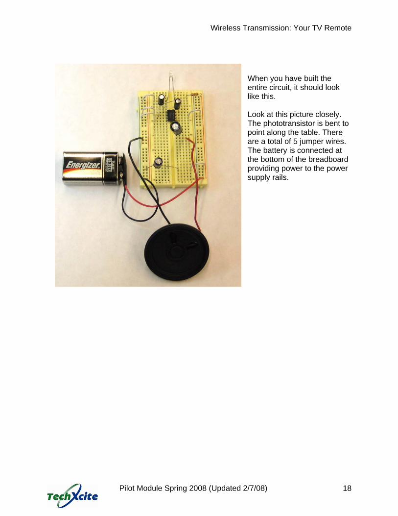
When you have built the entire circuit, it should look like this. Look at this picture closely. The phototransistor is bent to point along the table. There are a total of 5 jumper wires. The battery is connected at the bottom of the breadboard providing power to the power supply rails.

Wireless Transmission: Your TV Remote
Pilot Module Spring 2008 (Updated 2/7/08) 19
Building the Opto Receiver Circuit The first component to place on your breadboard is the LM 386 IC. With the notched end of the IC toward the top of your breadboard, gently insert the IC into the breadboard with pins 4 and 5, the two opposite the notch, in row 10. Using 2” jumper wires, connect pins 2 and 4 of the LM 386 IC to ground (blue negative rail) and pin 6 to the +9 V power (red positive rail). Remember that all five holes in one row are connected together. When you are instructed to connect pin 4 of the IC to ground, you can insert the jumper wire in any of the vacant holes in the row containing pin 4.
Try to make your connections look like those in the pictures. The connections you have just made provide power to the LM 386 IC.
Connect C2 (47 μF) between the power supply rails using a 2” jumper wire to complete the stretch across the breadboard. Be sure that the negative lead of C2 is connected to ground (negative power supply rail). Connect C3 (10 μF) between pins 1 and 8 of the IC. Be sure that the negative lead is connected to pin 8. Look at the picture to the left and note how the positive lead of C3 has been bent over the IC. The capacitor C2 stabilizes the voltage to the entire circuit. The capacitor C3 stabilizes the voltage to the LM 386 IC.
Wireless Transmission: Your TV Remote
Pilot Module Spring 2008 (Updated 2/7/08) 20
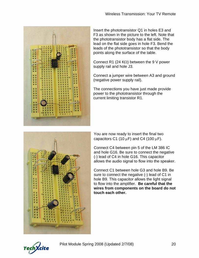
Insert the phototransistor Q1 in holes E3 and F3 as shown in the picture to the left. Note that the phototransistor body has a flat side. The lead on the flat side goes in hole F3. Bend the leads of the phototransistor so that the body points along the surface of the table. Connect R1 (24 KΩ) between the 9 V power supply rail and hole J3. Connect a jumper wire between A3 and ground (negative power supply rail). The connections you have just made provide power to the phototransistor through the current limiting transistor R1. You are now ready to insert the final two capacitors C1 (10 μF) and C4 (100 μF). Connect C4 between pin 5 of the LM 386 IC and hole G16. Be sure to connect the negative (-) lead of C4 in hole G16. This capacitor allows the audio signal to flow into the speaker. Connect C1 between hole G3 and hole B9. Be sure to connect the negative (-) lead of C1 in hole B9. This capacitor allows the light signal to flow into the amplifier. Be careful that the wires from components on the board do not touch each other.
Wireless Transmission: Your TV Remote
Pilot Module Spring 2008 (Updated 2/7/08) 21
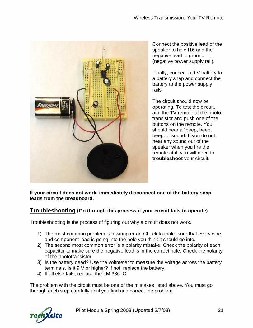
Connect the positive lead of the speaker to hole I16 and the negative lead to ground (negative power supply rail). Finally, connect a 9 V battery to a battery snap and connect the battery to the power supply rails. The circuit should now be operating. To test the circuit, aim the TV remote at the photo- transistor and push one of the buttons on the remote. You should hear a “beep, beep, beep…” sound. If you do not hear any sound out of the speaker when you fire the remote at it, you will need to troubleshoot your circuit.
If your circuit does not work, immediately disconnect one of the battery snap leads from the breadboard. Troubleshooting (Go through this process if your circuit fails to operate) Troubleshooting is the process of figuring out why a circuit does not work.
1) The most common problem is a wiring error. Check to make sure that every wire and component lead is going into the hole you think it should go into.
2) The second most common error is a polarity mistake. Check the polarity of each capacitor to make sure the negative lead is in the correct hole. Check the polarity of the phototransistor.
3) Is the battery dead? Use the voltmeter to measure the voltage across the battery terminals. Is it 9 V or higher? If not, replace the battery.
4) If all else fails, replace the LM 386 IC. The problem with the circuit must be one of the mistakes listed above. You must go through each step carefully until you find and correct the problem.
Wireless Transmission: Your TV Remote
Pilot Module Spring 2008 (Updated 2/7/08) 22
Exploring the Opto Receiver Circuit Infrared (IR) light is invisible. You cannot see the IR light that is emitted from the TV remote. But you know that the TV remote is emitting IR light because when you fire it at the opto receiver, you can hear the signal coming out of the speaker. Exploration 1: Take turns with your partner firing the TV remote at the photo transistor from different distances and angles. What happens it you put something (like a piece of paper) between the remote and photo transistor? Discuss with your partner what you observe and what you think causes the system to respond the way that it does. What is the purpose of the photo transistor in the circuit? Write down below what you observe and possible explanations: Exploration 2: Use the tape measure to determine the farthest distance the TV remote can be fired and still trigger a sound in the opto receiver. Compare your result with other teams in your class. Discuss why your results are different. What is the farthest distance the TV remote can be fired and still trigger a sound in the opto receiver? Answer: Storing Your Opto Receiver You will need to store your opto receiver for use during the next two activities. However, disconnect your battery from the breadboard and remove the battery snap. This will maximize the life of your battery. Your instructor may collect the batteries.